US5161069A - Curvilinear motion type optical filter driving mechanism - Google Patents
Curvilinear motion type optical filter driving mechanism Download PDFInfo
- Publication number
- US5161069A US5161069A US07/733,184 US73318491A US5161069A US 5161069 A US5161069 A US 5161069A US 73318491 A US73318491 A US 73318491A US 5161069 A US5161069 A US 5161069A
- Authority
- US
- United States
- Prior art keywords
- optical filter
- lens
- driving mechanism
- filter
- house
- Prior art date
- Legal status (The legal status is an assumption and is not a legal conclusion. Google has not performed a legal analysis and makes no representation as to the accuracy of the status listed.)
- Expired - Fee Related
Links
- 230000003287 optical effect Effects 0.000 title claims abstract description 30
- 230000007246 mechanism Effects 0.000 title claims abstract description 15
- 230000005540 biological transmission Effects 0.000 description 2
- 230000005484 gravity Effects 0.000 description 1
Images


Classifications
-
- G—PHYSICS
- G02—OPTICS
- G02B—OPTICAL ELEMENTS, SYSTEMS OR APPARATUS
- G02B26/00—Optical devices or arrangements for the control of light using movable or deformable optical elements
- G02B26/007—Optical devices or arrangements for the control of light using movable or deformable optical elements the movable or deformable optical element controlling the colour, i.e. a spectral characteristic, of the light
Definitions
- the present invention relates to optical filter driving mechanisms and relates more particularly to an optical filter driving mechanism to drive an optical filter to move in curvilinear direction.
- Conventional optical filter driving mechanism is generally operated through belt transmission. Disadvantage of this conventional optical filter driving mechanism is that the driving belt may be caused to deform easily, due to the gravity and the inertia of the filter frame. If the driving belt is deformed during driving operation, the optical filter will vibrate when it is carried to move in front of lens. Further, because the optical filter is driven to make a reciprocating, linear motion, the extended size of the filter frame occupies much space and, a wider space must be prepared for the linear motion of the optical filter. For example, if the optical filter is consisted of 4 pieces of filter at the front of lens 11 of lens-house 1 as shown in FIG. 1, the total track of the filter frame must be wider than the length of filter frame 2 and, a space wider than the total length of 7 pieces of filter must be provided for the reciprocating motion of the optical filter 3.
- the present invention has been accomplished to eliminate the aforesaid problems. It is therefore an object of the present invention to provide an optical filter driving mechanism which drives an optical filter to make a curvilinear motion during a filter selection operation.
- FIG. 1 illustrates the linear, reciprocating moving course of an optical filter driven by a conventional driving mechanism according to the prior art
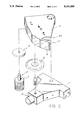
- FIG. 2 is an exploded perspective view of the preferred embodiment of the optical filter driving mechanism of the present invention
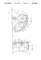
- FIG. 3 is a sectional assembly view of the preferred embodiment of the optical filter driving mechanism of the present invention.
- FIG. 4 is a schematic top view of the preferred embodiment of the optical filter driving mechanism of the present invention.
- FIG. 5 is a schematic drawing showing the operation of the present invention in driving the optical filter 3 to make a curvilinear motion.
- the optical filter driving mechanism of the present invention which is generally comprised of a lens-house 1, a fan-shaped filter holder 2, an optical filter 3 including a series of filters, a motor 4, a drive gear 5 and a driven gear 6.
- the drive gear 5 is mounted on the output shaft 41 of the motor 4 and engaged with the driven gear 6.
- the driven gear 6 is mounted on the lens-house 1 at the top and driven to rotate around a pivot pin 22 by the motor 4 via the drive gear 5.
- the filter holder 2 comprises an elongated, curved rack 21 below the front edge. During assembly process, the filter holder 2 is mounted on the lens-house 1 by the pivot pin 22 at a suitable location with the rack 21 engaged with the driven gear 6, permitting the optical filter 3 to be disposed in front of the lens 11.
Landscapes
- Physics & Mathematics (AREA)
- Astronomy & Astrophysics (AREA)
- Spectroscopy & Molecular Physics (AREA)
- General Physics & Mathematics (AREA)
- Optics & Photonics (AREA)
- Structure And Mechanism Of Cameras (AREA)
- Lens Barrels (AREA)
- Blocking Light For Cameras (AREA)
Abstract
A curvilinear motion type optical filter driving mechanism, comprising a lens-house, a filter holder, a motor, a driven gear, and a driving gear. The filter holder has an optical filter mounted thereon at the front and disposed in a curvilinear direction, and a rack at the back. Rotating the motor causes the drive gear to carry the optical filter, via the driven gear and the rack, to make a curvilinear motion over the lens of the lens-house.
Description
The present invention relates to optical filter driving mechanisms and relates more particularly to an optical filter driving mechanism to drive an optical filter to move in curvilinear direction.
Conventional optical filter driving mechanism is generally operated through belt transmission. Disadvantage of this conventional optical filter driving mechanism is that the driving belt may be caused to deform easily, due to the gravity and the inertia of the filter frame. If the driving belt is deformed during driving operation, the optical filter will vibrate when it is carried to move in front of lens. Further, because the optical filter is driven to make a reciprocating, linear motion, the extended size of the filter frame occupies much space and, a wider space must be prepared for the linear motion of the optical filter. For example, if the optical filter is consisted of 4 pieces of filter at the front of lens 11 of lens-house 1 as shown in FIG. 1, the total track of the filter frame must be wider than the length of filter frame 2 and, a space wider than the total length of 7 pieces of filter must be provided for the reciprocating motion of the optical filter 3.
The present invention has been accomplished to eliminate the aforesaid problems. It is therefore an object of the present invention to provide an optical filter driving mechanism which drives an optical filter to make a curvilinear motion during a filter selection operation.
It is another object of the present invention to provide an optical filter driving mechanism which reduces space occupation during operation.
It is still another object of the present invention to provide a gear driving mechanism which is stable in use.
FIG. 1 illustrates the linear, reciprocating moving course of an optical filter driven by a conventional driving mechanism according to the prior art;
FIG. 2 is an exploded perspective view of the preferred embodiment of the optical filter driving mechanism of the present invention;
FIG. 3 is a sectional assembly view of the preferred embodiment of the optical filter driving mechanism of the present invention;
FIG. 4 is a schematic top view of the preferred embodiment of the optical filter driving mechanism of the present invention; and
FIG. 5 is a schematic drawing showing the operation of the present invention in driving the optical filter 3 to make a curvilinear motion.
Referring to FIG. 2, therein illustrated is the preferred embodiment of the optical filter driving mechanism of the present invention which is generally comprised of a lens-house 1, a fan-shaped filter holder 2, an optical filter 3 including a series of filters, a motor 4, a drive gear 5 and a driven gear 6. The drive gear 5 is mounted on the output shaft 41 of the motor 4 and engaged with the driven gear 6. The driven gear 6 is mounted on the lens-house 1 at the top and driven to rotate around a pivot pin 22 by the motor 4 via the drive gear 5. The filter holder 2 comprises an elongated, curved rack 21 below the front edge. During assembly process, the filter holder 2 is mounted on the lens-house 1 by the pivot pin 22 at a suitable location with the rack 21 engaged with the driven gear 6, permitting the optical filter 3 to be disposed in front of the lens 11.
Referring to FIGS. 3 through 5, turning on the motor 4 causes the drive gear 5 to drive the driven gear 6 to rotate. Because the driven gear 6 is simultaneously engaged with the rack 21 so the optical filter 3 will make a curvilinear motion in front of the lens 11 of the lens-house 1. Because the optical filter is driven to make a curvilinear motion by means of gear power transmission, it does not vibrate while moving, and therefore, better performance is achieved.
Claims (1)
1. An optical filter assembly including a driving mechanism, comprising:
a lens-house having a lens at the front;
a filter holder mounted on said lens-house at the top, said filter holder having a curved rack below a front edge of the filter holder;
an optical filter fixedly mounted on said filter holder and disposed in front of said lens;
a motor having an output shaft;
a drive gear driven by said output shaft of said motor;
a driven gear mounted on said lens-house at the top end engaged between said drive gear and said rack; and
characterized in that rotating said motor causes said drive gear to carry said optical filter, via said driven gear and said rack, to make a curvilinear motion over said lens.
Priority Applications (1)
| Application Number | Priority Date | Filing Date | Title |
|---|---|---|---|
| US07/733,184 US5161069A (en) | 1991-07-19 | 1991-07-19 | Curvilinear motion type optical filter driving mechanism |
Applications Claiming Priority (1)
| Application Number | Priority Date | Filing Date | Title |
|---|---|---|---|
| US07/733,184 US5161069A (en) | 1991-07-19 | 1991-07-19 | Curvilinear motion type optical filter driving mechanism |
Publications (1)
| Publication Number | Publication Date |
|---|---|
| US5161069A true US5161069A (en) | 1992-11-03 |
Family
ID=24946583
Family Applications (1)
| Application Number | Title | Priority Date | Filing Date |
|---|---|---|---|
| US07/733,184 Expired - Fee Related US5161069A (en) | 1991-07-19 | 1991-07-19 | Curvilinear motion type optical filter driving mechanism |
Country Status (1)
| Country | Link |
|---|---|
| US (1) | US5161069A (en) |
Cited By (2)
| Publication number | Priority date | Publication date | Assignee | Title |
|---|---|---|---|---|
| US5276556A (en) * | 1992-12-28 | 1994-01-04 | Silitek Corporation | Color separation system for a color scanner |
| US5363247A (en) * | 1993-01-06 | 1994-11-08 | Must Systems, Inc. | Filter device for color optical scanners |
Citations (1)
| Publication number | Priority date | Publication date | Assignee | Title |
|---|---|---|---|---|
| US4943142A (en) * | 1986-02-11 | 1990-07-24 | University Of Massachusetts Medical Center | Imaging microspectrofluorimeter |
-
1991
- 1991-07-19 US US07/733,184 patent/US5161069A/en not_active Expired - Fee Related
Patent Citations (1)
| Publication number | Priority date | Publication date | Assignee | Title |
|---|---|---|---|---|
| US4943142A (en) * | 1986-02-11 | 1990-07-24 | University Of Massachusetts Medical Center | Imaging microspectrofluorimeter |
Cited By (2)
| Publication number | Priority date | Publication date | Assignee | Title |
|---|---|---|---|---|
| US5276556A (en) * | 1992-12-28 | 1994-01-04 | Silitek Corporation | Color separation system for a color scanner |
| US5363247A (en) * | 1993-01-06 | 1994-11-08 | Must Systems, Inc. | Filter device for color optical scanners |
Similar Documents
| Publication | Publication Date | Title |
|---|---|---|
| US5307716A (en) | Sheet material cutting device | |
| CA2191264A1 (en) | Reciprocating Drive Mechanism | |
| US5254042A (en) | Transmission device assembly for a bicycle | |
| JPH0618777Y2 (en) | Left-right feed reversing device for polishing table | |
| EP0658404A1 (en) | Industrial robot | |
| US5161069A (en) | Curvilinear motion type optical filter driving mechanism | |
| JP3212876B2 (en) | Reversing mechanism of moving body and turret reciprocating mechanism of sheet material cutting device using the reversing mechanism | |
| CA2195117A1 (en) | Gear Driven Roller Brush | |
| US5497272A (en) | Lens switching device for multi-lens optical scanners | |
| US4478010A (en) | In-line sander | |
| EP0257532B1 (en) | Card accessing apparatus | |
| EP0276341A1 (en) | Motion converting device | |
| JP2731866B2 (en) | Belt drive type robot | |
| US6101860A (en) | Shaping device of a wire bending machine | |
| JPH09117891A (en) | Circle cutter | |
| US5022157A (en) | Transmission mechanism for scroll sawing machine | |
| FR2664550B1 (en) | DEVICE FOR MOUNTING A DRIVE SHAFT, PARTICULARLY FOR WINDSCREEN WIPERS. | |
| US5385063A (en) | Transmission mechanism for magnetic damping type step machine | |
| JPH08229882A (en) | Sheet material cutting device | |
| JP2531017B2 (en) | Cassette loading device | |
| CN114850993A (en) | Notebook computer aluminum shell surface wire drawing device | |
| JP2716353B2 (en) | Facsimile round blade rotary cutter | |
| JPS6292205U (en) | ||
| JP2572556Y2 (en) | Support structure for the circling belt for wiper | |
| JP2738065B2 (en) | Paper storage device |
Legal Events
| Date | Code | Title | Description |
|---|---|---|---|
| AS | Assignment |
Owner name: TAMARACK TELECOM INC., TAIWAN Free format text: ASSIGNMENT OF ASSIGNORS INTEREST.;ASSIGNOR:JOWANG, FU;REEL/FRAME:006172/0909 Effective date: 19920618 |
|
| FEPP | Fee payment procedure |
Free format text: PAYOR NUMBER ASSIGNED (ORIGINAL EVENT CODE: ASPN); ENTITY STATUS OF PATENT OWNER: SMALL ENTITY |
|
| FPAY | Fee payment |
Year of fee payment: 4 |
|
| REMI | Maintenance fee reminder mailed | ||
| LAPS | Lapse for failure to pay maintenance fees | ||
| FP | Lapsed due to failure to pay maintenance fee |
Effective date: 20001103 |
|
| STCH | Information on status: patent discontinuation |
Free format text: PATENT EXPIRED DUE TO NONPAYMENT OF MAINTENANCE FEES UNDER 37 CFR 1.362 |