US5141476A - Two-way-driven 3-speed free wheel - Google Patents
Two-way-driven 3-speed free wheel Download PDFInfo
- Publication number
- US5141476A US5141476A US07/726,206 US72620691A US5141476A US 5141476 A US5141476 A US 5141476A US 72620691 A US72620691 A US 72620691A US 5141476 A US5141476 A US 5141476A
- Authority
- US
- United States
- Prior art keywords
- outer ring
- ratchet
- driven
- way
- bearing collar
- Prior art date
- Legal status (The legal status is an assumption and is not a legal conclusion. Google has not performed a legal analysis and makes no representation as to the accuracy of the status listed.)
- Expired - Lifetime
Links
Images


Classifications
-
- B—PERFORMING OPERATIONS; TRANSPORTING
- B62—LAND VEHICLES FOR TRAVELLING OTHERWISE THAN ON RAILS
- B62L—BRAKES SPECIALLY ADAPTED FOR CYCLES
- B62L5/00—Brakes, or actuating mechanisms therefor, controlled by back-pedalling
-
- F—MECHANICAL ENGINEERING; LIGHTING; HEATING; WEAPONS; BLASTING
- F16—ENGINEERING ELEMENTS AND UNITS; GENERAL MEASURES FOR PRODUCING AND MAINTAINING EFFECTIVE FUNCTIONING OF MACHINES OR INSTALLATIONS; THERMAL INSULATION IN GENERAL
- F16D—COUPLINGS FOR TRANSMITTING ROTATION; CLUTCHES; BRAKES
- F16D41/00—Freewheels or freewheel clutches
- F16D41/24—Freewheels or freewheel clutches specially adapted for cycles
- F16D41/30—Freewheels or freewheel clutches specially adapted for cycles with hinged pawl co-operating with teeth, cogs, or the like
-
- B—PERFORMING OPERATIONS; TRANSPORTING
- B62—LAND VEHICLES FOR TRAVELLING OTHERWISE THAN ON RAILS
- B62M—RIDER PROPULSION OF WHEELED VEHICLES OR SLEDGES; POWERED PROPULSION OF SLEDGES OR SINGLE-TRACK CYCLES; TRANSMISSIONS SPECIALLY ADAPTED FOR SUCH VEHICLES
- B62M11/00—Transmissions characterised by the use of interengaging toothed wheels or frictionally-engaging wheels
- B62M11/04—Transmissions characterised by the use of interengaging toothed wheels or frictionally-engaging wheels of changeable ratio
- B62M11/14—Transmissions characterised by the use of interengaging toothed wheels or frictionally-engaging wheels of changeable ratio with planetary gears
- B62M11/16—Transmissions characterised by the use of interengaging toothed wheels or frictionally-engaging wheels of changeable ratio with planetary gears built in, or adjacent to, the ground-wheel hub
Definitions
- This invention relates to a multi-gear changing mechanism for use with various kinds of bicycle pedals. It is, in specific terms, a 3-speed free wheel operated by forward or backward pedalling.
- a two-way-driven 2-speed free wheel (New utility model patent NO. 8520575, Chinese Patent Office) which is capable of gear-changing as well as motion transmission. It is composed of a sprocket wheel, a central gear, catches, cones, etc. It is characterized in that the sprocket wheel has sprockets on the outer edge and gear teeth on the inner edge. Between the sprocket wheel and central gear there are two or more planet pinions fixed on a planet pinion bearing collar and engaging with the central gear and the inner teeth of the sprocket wheel.
- a catch hinged on the bottom forks of a bicycle (hereafter referred to as an outer catch), has its tapered end fitted into the ratchet teeth on the side of the planet pinion bearing collar or into outer ratchet teeth on an outer ring.
- the sprocket wheel of the free wheel will rotate in the same direction and the inner catches will not be interlocked with the planet pinions and the planet pinion bearings.
- the planet pinions, engaged with the inner teeth of the sprocket wheel, as well as the planet pinion bearings are being pushed to rotate with it in a backward direction.
- the planet pinion bearing collar is stopped by the catch hinged on the bottom forks, so the planet pinions can only turn to drive the central gear in a forward direction.
- the back-pedalling of the chain wheel causes the bicycle to go forward as usual, but in a higher speed.
- That device has a variation model, one-way-drive 2-speed free wheel. Its structure is a little different.
- the sprocket wheel has no inner teeth, while an outer ring has. Each of them can rotate independently of the other.
- the outer ring has outer ratchet teeth on its outer edge, to be locked by the outer catch.
- the sprocket wheel is fastened with the planet bearing collar by a screw thread fitting.
- the planet pinion bearing is to rotate in a forward direction with the forward rotation of the sprocket wheel and cause the outer ring to rotate in a backward direction. But since the inner teeth of the outer ring are locked with the inner catches, the planet pinions keep from turning. Under such condition the central gear rotates with the sprocket wheel at the same speed and the bicycle runs in low gear.
- Both of the above-mentioned structures are simpler than the prevailing built-in gear-changing mechanism or the outer one. Compact in form, they are secure and withstand wear and tear. Each can easily be installed on an ordinary pedal cycle. Besides, each can be installed on a fitness bike.
- This invention is meant to improve on these two structures by overcoming their shortcoming and combining the two into a new model: a two-way-drive-3-speed free wheel.
- the inner catches are replaced by two pairs of pawls hinged on the sprocket wheel to control the direction of motion transmission. Since they are placed externally, they are bigger in size and, consequently, stronger and tougher.
- a symmetric sprocket wheel is replaced by an asymmetric one.
- the inner teeth of the sprocket wheel are dispensed with.
- the inner teeth of the sprocket wheel are replaced by the inner teeth of the outer ring to mesh with the planet pinions.
- the outer edge of the outer ring has double ratchet gullets so that it can be installed the other way round for longer life when the ratchet teeth are worn.
- a ratchet cone to regulate the gap of the ball race of the sprocket wheel and drive the bearing collar.
- the outer edge of the ratchet cone has ratchet teeth. It can impart clockwise motion when it is locked with the pawls. When the ratchet teeth on the outer ring are locked with the pawls, they can impart counter clockwise motion. So the central gear always rotates clockwise, no matter how the sprocket wheel turns.
- FIGS. 1a and 1b are structural drawings of the two-way-driven 3-speed free wheel according to the present invention.
- FIGS. 2a and 2b are structural drawings of a one-way-driven (forward pedalling) 2-speed free wheel according to the present invention.
- FIGS. 3a and 3b are structural drawings of a two-way-driven 2-speed free wheel according to the present invention.
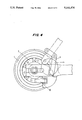
- FIG. 4 is an assembly drawing in which a two-way-driven 3-speed free wheel has been assembled on a bicycle.
- reference character 1 represents a sprocket wheel. This sprocket wheel has sprocket teeth on the outer edge, and a ball race on the inner edge.
- Reference character 2 represents an outer ring, having a ratchet gullet on its outer edge and internal toothing on its inner edge.
- Reference character 3 is a bearing collar, and as shown is a self-aligning bearing with internal and external ball races.
- Reference character 4 denotes a central gear, with an internal screw thread.
- Reference characters 5 and 6 respectively represent cones (bearings) and a ratchet cone (the ratchet cone having ratchet teeth on its outer edge).
- Reference character 7 represents planet pinions; two or more are used.
- Reference character 8 denotes screwed cones, and reference character 9 represents balls (4 sets).
- Reference character 10 denotes a pawl
- reference character 11 represents a hook pawl
- Reference characters 12 and 13 respectively represent backward pawls and forward pawls.
- Reference character 14 represents planetary spindles (supporting spindles), and reference character 15 represents small spindles (for the pawls).
- This invention is composed of a sprocket wheel, an outer ring, a central gear, a bearing collar, screwed cones, pawls and planet pinions. It is characterized in that there are four kinds of catches: pawl 10, hook-pawl 11, backward pawls 12, and forward pawls 13. Pawls 12 and 13 are hinged on both sides of the sprocket wheel by small spindles 15. On one side are backward pawls 12 and outer ring 2. On the other side are forward pawls 13, ratchet cone 6 and bearing collar 3. Between outer ring 2 and central gear 4 are two or more planet pinions 7.
- Outer ring 2 has a double ratchet gullet on the outer edge for pawls 12 to engage with and thus get locked.
- Ratchet cone 6 has ratchet teeth on the outer edge for pawls 13 to engage with and thus get locked.
- the tapered end of pawl 10 fits into the ratchet teeth on the side of bearing collar 3 so as to lock it.
- the hooked end of hook-pawl 11 fits into the ratchet gullet of outer ring 2 so as to lock it.
- Both pawls 10 and 11 are hinged on the bottom forks of a bicycle (see, e.g., FIG. 4).
- the planet pinions and some other parts of this invention have the same structure as those on the two-way-driven 2-speed free wheel which is the prior art designed by the same inventor.
- outer ring 2 is locked by pawl 11.
- bearing collar 3 rotates with it under the action of forward pawl 13, unhindered by pawls 12 and 10.
- central gear 4 drives central gear 4 to rotate clockwise.
- the speed of rotation of central gear 4 is still greater than that of outer ring 2 and is augmented by the orbital revolution of planet pinions 7. High gear operation is thus effected.
- This invention can be adapted to practical needs for two simplified models of a 2-speed free wheel:
- Bearing collar 3 has no ratchet teeth and ratchet cone 6 is dispensed with.
- FIGS. 2a and 2b are structural drawings of this model.
- FIGS. 3a and 3b are structural drawings of this model.
- FIG. 4 is the assembly diagram in which a two-way-driven 3-speed free wheel has been assembled on a bicycle.
Landscapes
- Engineering & Computer Science (AREA)
- Mechanical Engineering (AREA)
- General Engineering & Computer Science (AREA)
- Chemical & Material Sciences (AREA)
- Combustion & Propulsion (AREA)
- Transportation (AREA)
- Structure Of Transmissions (AREA)
- Retarders (AREA)
- Transmission Devices (AREA)
Applications Claiming Priority (2)
| Application Number | Priority Date | Filing Date | Title |
|---|---|---|---|
| CN90105171A CN1032797C (zh) | 1990-07-10 | 1990-07-10 | 双向三级变速飞轮 |
| CN90105171.3 | 1990-07-10 |
Publications (1)
| Publication Number | Publication Date |
|---|---|
| US5141476A true US5141476A (en) | 1992-08-25 |
Family
ID=4879003
Family Applications (1)
| Application Number | Title | Priority Date | Filing Date |
|---|---|---|---|
| US07/726,206 Expired - Lifetime US5141476A (en) | 1990-07-10 | 1991-07-05 | Two-way-driven 3-speed free wheel |
Country Status (6)
| Country | Link |
|---|---|
| US (1) | US5141476A (enExample) |
| JP (1) | JPH0489492U (enExample) |
| KR (1) | KR940007572Y1 (enExample) |
| CN (1) | CN1032797C (enExample) |
| AU (1) | AU640244B2 (enExample) |
| CA (1) | CA2046432A1 (enExample) |
Cited By (9)
| Publication number | Priority date | Publication date | Assignee | Title |
|---|---|---|---|---|
| US5647817A (en) * | 1994-11-23 | 1997-07-15 | Steven Siuwai Lam | Two directional multi-speed shifting gear of middle axle |
| US5954614A (en) * | 1998-01-20 | 1999-09-21 | World Industry Co., Ltd. | Apparatus for changing power direction for bicycle |
| US5957802A (en) * | 1997-06-09 | 1999-09-28 | World Industry Co., Ltd. | Apparatus for changing rotation of pedal shaft for bicycle |
| US6045475A (en) * | 1996-12-30 | 2000-04-04 | World Industry Co., Ltd. | Controller for a changeable pedaling system in a bi-directional pedaling bicycle |
| US6142904A (en) * | 1999-03-15 | 2000-11-07 | World Industry Co., Ltd. | Apparatus for changing direction of driving force for bicycles |
| ES2155020A1 (es) * | 1999-04-21 | 2001-04-16 | Valdez Cuauhtemoctzin Castro | Bicicleta de doble traccion |
| US6383108B1 (en) * | 1999-06-30 | 2002-05-07 | World Industry Co., Ltd., | Apparatus for changing direction of driving force for bicycles |
| CN102414078A (zh) * | 2009-04-30 | 2012-04-11 | Ntn株式会社 | 具备再生机构的电动辅助自行车 |
| CN106585268A (zh) * | 2016-11-03 | 2017-04-26 | 杭州否科技有限公司 | 一种车轮以及采用该车轮的车辆 |
Families Citing this family (9)
| Publication number | Priority date | Publication date | Assignee | Title |
|---|---|---|---|---|
| JP5545520B2 (ja) * | 2009-05-22 | 2014-07-09 | Ntn株式会社 | 回生機構を備えた電動補助自転車 |
| CN102506141A (zh) * | 2010-01-02 | 2012-06-20 | 沈维聪 | 低速逆转同步器 |
| TW201236919A (en) * | 2011-03-08 | 2012-09-16 | Bo-Cheng Chen | Driving device for bike |
| CN104883000B (zh) * | 2015-05-25 | 2017-06-06 | 严振华 | 电动自行车用可变减速比的轮毂电机 |
| CN105539716B (zh) * | 2015-12-24 | 2018-01-05 | 张学田 | 一种设有多档快捷变速的自行车双轮盘 |
| CN106494562B (zh) * | 2016-08-31 | 2022-02-01 | 张家港川梭车业有限公司 | 一种全自动三级变速驱动装置 |
| CN106741559A (zh) * | 2017-01-23 | 2017-05-31 | 吴利祥 | 一种脚蹬正转反转均能前行的无链式健身自行车 |
| CN106985963B (zh) * | 2017-05-11 | 2022-06-07 | 张家港川梭车业有限公司 | 单轮驱动三挡变速装置 |
| CN110436317B (zh) * | 2019-09-05 | 2023-10-20 | 张明 | 一种电梯曳引机排车装置 |
Citations (3)
| Publication number | Priority date | Publication date | Assignee | Title |
|---|---|---|---|---|
| US4240533A (en) * | 1977-05-06 | 1980-12-23 | Shimano Industrial Company, Limited | Coaster brake hub with a gear-transmission |
| US4628769A (en) * | 1983-11-29 | 1986-12-16 | Shimano Industrial Company Limited | Speed change hub for a bicycle |
| US4727965A (en) * | 1983-11-09 | 1988-03-01 | Sanitatshaus Heinrich Oesterreich Gmbh | Geared hub with freewheel, especially for wheel-chairs |
-
1990
- 1990-07-10 CN CN90105171A patent/CN1032797C/zh not_active Expired - Fee Related
-
1991
- 1991-07-05 US US07/726,206 patent/US5141476A/en not_active Expired - Lifetime
- 1991-07-08 CA CA002046432A patent/CA2046432A1/en not_active Abandoned
- 1991-07-10 JP JP1991061448U patent/JPH0489492U/ja active Pending
- 1991-07-10 AU AU80356/91A patent/AU640244B2/en not_active Ceased
- 1991-07-10 KR KR2019910010587U patent/KR940007572Y1/ko not_active Expired - Lifetime
Patent Citations (3)
| Publication number | Priority date | Publication date | Assignee | Title |
|---|---|---|---|---|
| US4240533A (en) * | 1977-05-06 | 1980-12-23 | Shimano Industrial Company, Limited | Coaster brake hub with a gear-transmission |
| US4727965A (en) * | 1983-11-09 | 1988-03-01 | Sanitatshaus Heinrich Oesterreich Gmbh | Geared hub with freewheel, especially for wheel-chairs |
| US4628769A (en) * | 1983-11-29 | 1986-12-16 | Shimano Industrial Company Limited | Speed change hub for a bicycle |
Cited By (12)
| Publication number | Priority date | Publication date | Assignee | Title |
|---|---|---|---|---|
| US5647817A (en) * | 1994-11-23 | 1997-07-15 | Steven Siuwai Lam | Two directional multi-speed shifting gear of middle axle |
| US6045475A (en) * | 1996-12-30 | 2000-04-04 | World Industry Co., Ltd. | Controller for a changeable pedaling system in a bi-directional pedaling bicycle |
| US5957802A (en) * | 1997-06-09 | 1999-09-28 | World Industry Co., Ltd. | Apparatus for changing rotation of pedal shaft for bicycle |
| US5954614A (en) * | 1998-01-20 | 1999-09-21 | World Industry Co., Ltd. | Apparatus for changing power direction for bicycle |
| US6142904A (en) * | 1999-03-15 | 2000-11-07 | World Industry Co., Ltd. | Apparatus for changing direction of driving force for bicycles |
| ES2155020A1 (es) * | 1999-04-21 | 2001-04-16 | Valdez Cuauhtemoctzin Castro | Bicicleta de doble traccion |
| US6383108B1 (en) * | 1999-06-30 | 2002-05-07 | World Industry Co., Ltd., | Apparatus for changing direction of driving force for bicycles |
| US6383107B1 (en) * | 1999-06-30 | 2002-05-07 | World Industry Co., Ltd. | Apparatus for changing direction of driving force for bicycles |
| CN102414078A (zh) * | 2009-04-30 | 2012-04-11 | Ntn株式会社 | 具备再生机构的电动辅助自行车 |
| EP2426041A4 (en) * | 2009-04-30 | 2012-12-05 | Ntn Toyo Bearing Co Ltd | ASSISTED CONTROL BICYCLE COMPRISING A REGENERATIVE MECHANISM |
| US8684122B2 (en) | 2009-04-30 | 2014-04-01 | Ntn Corporation | Power assisted bicycle with regenerative function |
| CN106585268A (zh) * | 2016-11-03 | 2017-04-26 | 杭州否科技有限公司 | 一种车轮以及采用该车轮的车辆 |
Also Published As
| Publication number | Publication date |
|---|---|
| JPH0489492U (enExample) | 1992-08-05 |
| AU640244B2 (en) | 1993-08-19 |
| KR940007572Y1 (ko) | 1994-10-22 |
| CN1032797C (zh) | 1996-09-18 |
| CA2046432A1 (en) | 1992-01-11 |
| CN1057996A (zh) | 1992-01-22 |
| AU8035691A (en) | 1992-01-16 |
| KR920002506U (ko) | 1992-02-24 |
Similar Documents
| Publication | Publication Date | Title |
|---|---|---|
| US5141476A (en) | Two-way-driven 3-speed free wheel | |
| US5399128A (en) | Multi-speed drive hub with a separate mounting ring for the planetary gearset for bicycles | |
| US3828627A (en) | Multiple-speed hub | |
| CN1056578C (zh) | 自行车轮毂动力变换装置 | |
| TWI649234B (zh) | 用於自行車的齒輪轂 | |
| US5527230A (en) | Multi-speed hub for bicycles | |
| US9139254B2 (en) | Universal low-friction bicycle hub transmission | |
| RU97115942A (ru) | Устройство преобразования мощности для велосипедной втулки | |
| WO2024207904A1 (zh) | 一种手自一体内变速花鼓及自行车 | |
| US5647817A (en) | Two directional multi-speed shifting gear of middle axle | |
| US3709053A (en) | Multi-speed transmission front gear mechanism for a bicycle | |
| US4183262A (en) | Gear crank for a bicycle | |
| US4782722A (en) | Bicycle drive system | |
| GB2263511A (en) | A driven free wheel change speed planetary gearing for bicycles | |
| US4702121A (en) | Multiple speed driving wheel for pedal powered vehicles | |
| US3433097A (en) | Epicyclic change speed gear hubs | |
| US2759373A (en) | Multiple speed bicycle transmission | |
| US3182529A (en) | Dual-speed hub | |
| US1998376A (en) | Motion transmitting means | |
| GB1467391A (en) | Multi-speed transmission hub for bicycles | |
| US3215002A (en) | Dual speed hub | |
| US2899030A (en) | Three speed bicycle transmission | |
| US3172305A (en) | Change speed transmission mechanism for bicycles | |
| JP2012025336A (ja) | モータ及びペダリング兼用変速機及び変速方法 | |
| CN206797623U (zh) | 一种单轮驱动三挡变速装置 |
Legal Events
| Date | Code | Title | Description |
|---|---|---|---|
| AS | Assignment |
Owner name: S.W.LAM Free format text: ASSIGNMENT OF ASSIGNORS INTEREST.;ASSIGNOR:CHANG, DIANLIN;REEL/FRAME:005768/0926 Effective date: 19910617 |
|
| STCF | Information on status: patent grant |
Free format text: PATENTED CASE |
|
| FEPP | Fee payment procedure |
Free format text: PAYOR NUMBER ASSIGNED (ORIGINAL EVENT CODE: ASPN); ENTITY STATUS OF PATENT OWNER: SMALL ENTITY |
|
| FPAY | Fee payment |
Year of fee payment: 4 |
|
| FPAY | Fee payment |
Year of fee payment: 8 |
|
| FPAY | Fee payment |
Year of fee payment: 12 |