US5127713A - Anti-lock brake system for automotive vehicles - Google Patents
Anti-lock brake system for automotive vehicles Download PDFInfo
- Publication number
- US5127713A US5127713A US07/281,299 US28129988A US5127713A US 5127713 A US5127713 A US 5127713A US 28129988 A US28129988 A US 28129988A US 5127713 A US5127713 A US 5127713A
- Authority
- US
- United States
- Prior art keywords
- lock
- pressure
- wheel brakes
- brake system
- pressure reduction
- Prior art date
- Legal status (The legal status is an assumption and is not a legal conclusion. Google has not performed a legal analysis and makes no representation as to the accuracy of the status listed.)
- Expired - Fee Related
Links
Images

Classifications
-
- B—PERFORMING OPERATIONS; TRANSPORTING
- B60—VEHICLES IN GENERAL
- B60T—VEHICLE BRAKE CONTROL SYSTEMS OR PARTS THEREOF; BRAKE CONTROL SYSTEMS OR PARTS THEREOF, IN GENERAL; ARRANGEMENT OF BRAKING ELEMENTS ON VEHICLES IN GENERAL; PORTABLE DEVICES FOR PREVENTING UNWANTED MOVEMENT OF VEHICLES; VEHICLE MODIFICATIONS TO FACILITATE COOLING OF BRAKES
- B60T13/00—Transmitting braking action from initiating means to ultimate brake actuator with power assistance or drive; Brake systems incorporating such transmitting means, e.g. air-pressure brake systems
- B60T13/10—Transmitting braking action from initiating means to ultimate brake actuator with power assistance or drive; Brake systems incorporating such transmitting means, e.g. air-pressure brake systems with fluid assistance, drive, or release
- B60T13/66—Electrical control in fluid-pressure brake systems
-
- B—PERFORMING OPERATIONS; TRANSPORTING
- B60—VEHICLES IN GENERAL
- B60T—VEHICLE BRAKE CONTROL SYSTEMS OR PARTS THEREOF; BRAKE CONTROL SYSTEMS OR PARTS THEREOF, IN GENERAL; ARRANGEMENT OF BRAKING ELEMENTS ON VEHICLES IN GENERAL; PORTABLE DEVICES FOR PREVENTING UNWANTED MOVEMENT OF VEHICLES; VEHICLE MODIFICATIONS TO FACILITATE COOLING OF BRAKES
- B60T8/00—Arrangements for adjusting wheel-braking force to meet varying vehicular or ground-surface conditions, e.g. limiting or varying distribution of braking force
- B60T8/26—Arrangements for adjusting wheel-braking force to meet varying vehicular or ground-surface conditions, e.g. limiting or varying distribution of braking force characterised by producing differential braking between front and rear wheels
-
- B—PERFORMING OPERATIONS; TRANSPORTING
- B60—VEHICLES IN GENERAL
- B60T—VEHICLE BRAKE CONTROL SYSTEMS OR PARTS THEREOF; BRAKE CONTROL SYSTEMS OR PARTS THEREOF, IN GENERAL; ARRANGEMENT OF BRAKING ELEMENTS ON VEHICLES IN GENERAL; PORTABLE DEVICES FOR PREVENTING UNWANTED MOVEMENT OF VEHICLES; VEHICLE MODIFICATIONS TO FACILITATE COOLING OF BRAKES
- B60T8/00—Arrangements for adjusting wheel-braking force to meet varying vehicular or ground-surface conditions, e.g. limiting or varying distribution of braking force
- B60T8/32—Arrangements for adjusting wheel-braking force to meet varying vehicular or ground-surface conditions, e.g. limiting or varying distribution of braking force responsive to a speed condition, e.g. acceleration or deceleration
- B60T8/88—Arrangements for adjusting wheel-braking force to meet varying vehicular or ground-surface conditions, e.g. limiting or varying distribution of braking force responsive to a speed condition, e.g. acceleration or deceleration with failure responsive means, i.e. means for detecting and indicating faulty operation of the speed responsive control means
- B60T8/92—Arrangements for adjusting wheel-braking force to meet varying vehicular or ground-surface conditions, e.g. limiting or varying distribution of braking force responsive to a speed condition, e.g. acceleration or deceleration with failure responsive means, i.e. means for detecting and indicating faulty operation of the speed responsive control means automatically taking corrective action
- B60T8/94—Arrangements for adjusting wheel-braking force to meet varying vehicular or ground-surface conditions, e.g. limiting or varying distribution of braking force responsive to a speed condition, e.g. acceleration or deceleration with failure responsive means, i.e. means for detecting and indicating faulty operation of the speed responsive control means automatically taking corrective action on a fluid pressure regulator
-
- C—CHEMISTRY; METALLURGY
- C08—ORGANIC MACROMOLECULAR COMPOUNDS; THEIR PREPARATION OR CHEMICAL WORKING-UP; COMPOSITIONS BASED THEREON
- C08L—COMPOSITIONS OF MACROMOLECULAR COMPOUNDS
- C08L79/00—Compositions of macromolecular compounds obtained by reactions forming in the main chain of the macromolecule a linkage containing nitrogen with or without oxygen or carbon only, not provided for in groups C08L61/00 - C08L77/00
- C08L79/02—Polyamines
-
- D—TEXTILES; PAPER
- D21—PAPER-MAKING; PRODUCTION OF CELLULOSE
- D21H—PULP COMPOSITIONS; PREPARATION THEREOF NOT COVERED BY SUBCLASSES D21C OR D21D; IMPREGNATING OR COATING OF PAPER; TREATMENT OF FINISHED PAPER NOT COVERED BY CLASS B31 OR SUBCLASS D21G; PAPER NOT OTHERWISE PROVIDED FOR
- D21H17/00—Non-fibrous material added to the pulp, characterised by its constitution; Paper-impregnating material characterised by its constitution
- D21H17/20—Macromolecular organic compounds
- D21H17/33—Synthetic macromolecular compounds
- D21H17/46—Synthetic macromolecular compounds obtained otherwise than by reactions only involving carbon-to-carbon unsaturated bonds
- D21H17/54—Synthetic macromolecular compounds obtained otherwise than by reactions only involving carbon-to-carbon unsaturated bonds obtained by reactions forming in the main chain of the macromolecule a linkage containing nitrogen
Definitions
- the present invention relates to an anti-lock brake system for automotive vehicles comprising a master cylinder, a device for modulating the pressure supplied to the brakes, an anti-lock control device with at least one monitoring device, and means for pressure reduction in the rear-axle brake circuit.
- a brake system of this type is known from German published patent application 33 29 706.
- a bypass line leading to the rear axle is simultaneously opened in order to utilize the reverse in brake force until the limit of locking of the rear wheels is reached.
- This brake system has the disadvantage that, when the anti-lock function commences, the rear-axle brakes will be abruptly applied with the full braking pressure corresponding to the wheel-lock pressure of the front axle instead of the controlled pressure, which results in unstable driving conditions, at least in the short term.
- an anti-lock brake system according to the present invention in that the means for the pressure reduction carries out the braking pressure reduction only upon failure or malfunction of the anti-lock function.
- the basic dimensioning of the brake force distribution between front-wheel brakes and rear-wheel brakes in the event of pressure reduction being ineffective provides for relatively heavily loaded rear-axle brakes. This basic dimensioning is selected such that, in the event of ineffective brake force reduction, the rear-axle brakes reach the limit of wheel lock before the front-axle brakes.
- a particularly advantagious embodiment of this invention provides that the means for pressure reduction are formed by at least one braking pressure reducer and around which a bypass line is arranged which can be opened or closed by a solenoid valve.
- the solenoid valve is designed as a solenoid valve which is closed in its de-energized state and which is energized when the anti-lock device is intact. It is thereby ensured that, even upon failure of the anti-lock device or even in the event of a defect in the electrical connection between solenoid valve and signal generator, the bypass is closed and the hydraulic communication between the master cylinder and the rear-wheel brakes is possible solely by way of the pressure reducer. This ensures that locking of the rear-wheel brakes is always prevented when an error occurs.
- FIG. 1 is an inventive anti-lock brake system in accordance with the principles of the present invention.
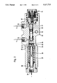
- FIG. 2 is a cross-sectional view of an alternative braking pressure reducer with blocking piston and solenoid valve for use in the system illustrated in FIG. 1.
- FIG. 1 schematically illustrates the essential hydraulical portion of an anti-lock brake system.
- the electrical part of the brake system is depicted only insofar as it is necessary for an understanding of this embodiment of the present invention. That is to say, the sensors for determining the rotational speed of the wheels, the connection of the sensors to the anti-lock control device 2 in which the monitoring device is integrated, and the connection from the solenoid valves 3, 4 for the pressure modulation to the motor 5 and to the anti-lock control device 2 are not shown. Likewise, the various switches and sensors for monitoring the system functions are not shown.
- the brake system comprises a tandem master cylinder 1 from which a front-axle brake circuit 6 and a rear-axle brake circuit 7 lead to the associated wheel brakes by way of solenoid valves 3 serving as an inlet.
- solenoid valves 3 serving as an inlet.
- the wheel brakes are each connectible by way of a solenoid valve 4 serving as an outlet with a return line leading to the reservoir.
- a switchable braking pressure control device 10 in the rear-axle brake circuit 7 is provided, whose inlet 11 is connected with the inlet chamber 12 of a braking pressure as is known per se.
- This braking pressure reducer substantially comprises the regulating piston 14 which is axially slidably and sealedly guided in the bore 13 and the regulating valve 15 contained in the latter piston, the regulating piston 14 being biassed by the control springs 16, 17 in the opening direction of the spring-loaded regulating valve 15. From the outlet chamber 18 of the braking pressure reducer, a channel extends by way of the annular chamber 19 to the outlet 20 of the braking pressure control device 10 and from there by way of the solenoid valves 3 to the rear-wheel brakes.
- a bypass line 21 branches off from the connection of the inlet 11 and the inlet chamber 12, which line can be opened or closed by a solenoid valve 22.
- This bypass line 21 is thus connectible by way of channels disposed in the solenoid valve 22 with the annular chamber 19 and, consequently, likewise by way of the outlet 20 with the wheel brakes.
- the solenoid valve 22 is designed as a solenoid valve which is closed in its de-energized state and is actuated by the relay 25 to which it connects by way of the line 24.
- This relay 25 opens the solenoid valve 22 when the contact of the brake light switch 27 is closed after depression of the brake pedal 28 and no control voltage is applied to the relay 25 by way of the line 29 which connects the relay 25 to the monitoring device provided in the anti-lock control device. If the monitoring device detects a malfunction, a control voltage will be produced which switches on the alarm lamp 30 and, isolates the line 24 from the voltage source.
- the basic dimensioning of brake force distribution is chosen such that the major load is heavily on or weighted toward the rear-axle brakes, which effectively relieves the front-wheel brakes from load in approximately 90% of all braking actions occurring in normal operation.
- This basic dimensioning of brake force distribution would result, that in the event of heavy braking, the rear wheels would lock before the front wheels do. This would result in unstable driving conditions as a consequence, if there were no anti-lock control and no pressure reduction means.
- the solenoid valves 3, 4 the pressure acting on the rear-wheel brakes is reduced by regulation to such degree that there is no longer a risk of wheel lock.
- the present invention provides that the bypass line 21 is closed upon failure of anti-lock control and that the connection from the tandem master cylinder 1 to the rear-wheel brakes is provided by way of the braking pressure reducer.
- FIG. 2 shows a braking pressure control device 32 which, in lieu of the braking pressure control device 10, can be mounted into a brake system according to FIG. 1.
- the rear-axle brake circuit 7 extends through the inlet 33 into an inlet chamber 31 in which also the valve closure member 34 is axially slidably provided in the main bore.
- This valve closure member 34 cooperates with a valve seat which is formed by the smaller end surface 35 of the regulating piston 36.
- the regulating piston 36 is provided as a differential piston with a through-bore and is biassed by the control spring 37 in the opening direction, that is, in the direction of the larger end surface 38.
- valve closure member 34 contains axially and radially extending channels 41, 42 adapted to be penetrated by fluid and includes a spherical sealing portion 43.
- the valve closure member 34 is anchored with the blocking piston 44 on the side which is axially opposite to the sealing portion 43.
- the sealedly displaceable blocking piston 44 projects with its end surface opposite to the valve closure member 34 into the pressure chamber 45, the end surface that is applicable by the pressure in the pressure chamber 45 being somewhat larger than the effective pressure-applied surface of the blocking piston 44 in the inlet chamber 31.
- a compression spring 47 preloads the blocking piston 44 in the direction of the pressure chamber 45.
- the blocking piston thereby will move into abutment on the housing of the solenoid valve 48.
- This solenoid valve 48 governs the connection between the pressure chamber 45 and the port 46 communicating with the front-axle brake circuit 6.
- the electric switching of the solenoid valve 48 is effected such that the connection between port 46 and pressure chamber 45 is closed when the anti-lock system is functioning, while it opens in the event of failure of the anti-lock system.
- the solenoid valve 48 is provided as a solenoid valve which is open in its de-energized state.
- the use of a braking pressure control device with blocking function has the additional advantage that, upon failure of the front-axle brake circuit, for example due to leakage, braking pressure reduction function is not applied and thus the rear-wheel brakes can be applied with the maximum braking pressure.
Abstract
Description
Claims (2)
Applications Claiming Priority (2)
| Application Number | Priority Date | Filing Date | Title |
|---|---|---|---|
| DE374173 | 1987-12-12 | ||
| DE19873742173 DE3742173A1 (en) | 1987-12-12 | 1987-12-12 | ANTI-BLOCKED BRAKE SYSTEM FOR MOTOR VEHICLES |
Publications (1)
| Publication Number | Publication Date |
|---|---|
| US5127713A true US5127713A (en) | 1992-07-07 |
Family
ID=6342458
Family Applications (1)
| Application Number | Title | Priority Date | Filing Date |
|---|---|---|---|
| US07/281,299 Expired - Fee Related US5127713A (en) | 1987-12-12 | 1988-12-07 | Anti-lock brake system for automotive vehicles |
Country Status (5)
| Country | Link |
|---|---|
| US (1) | US5127713A (en) |
| JP (1) | JPH01257652A (en) |
| DE (1) | DE3742173A1 (en) |
| FR (1) | FR2624462B1 (en) |
| GB (1) | GB2213543B (en) |
Cited By (7)
| Publication number | Priority date | Publication date | Assignee | Title |
|---|---|---|---|---|
| US5267782A (en) * | 1991-11-28 | 1993-12-07 | Robert Bosch Gmbh | Hydraulic brake system, in particular for motor vehicles |
| US5390987A (en) * | 1993-03-08 | 1995-02-21 | Kelsey-Hayes Company | Brake system metering valve with a pressure actuated brake switch |
| US5480221A (en) * | 1991-11-29 | 1996-01-02 | Mitsubishi Jidosha Kogyo Kabushiki Kaisha | Rear wheel braking force control method and an apparatus therefor |
| US5558415A (en) * | 1992-07-29 | 1996-09-24 | Itt Automotive Europe Gmbh | Method of enhancing the reliablity in operation of a brake system with electronic control of the brake force distribution |
| US5899540A (en) * | 1992-12-02 | 1999-05-04 | Itt Automotive Europe Gmbh | Brake system including anti-lock control and electronic brake force distribution |
| US20040135432A1 (en) * | 2003-01-14 | 2004-07-15 | Delphi Technologies Inc. | Failsafe operation of a hybrid brake system for a vehicle |
| US20180148025A1 (en) * | 2016-11-30 | 2018-05-31 | Robert Bosch Gmbh | Electronically slip-controllable braking system |
Families Citing this family (19)
| Publication number | Priority date | Publication date | Assignee | Title |
|---|---|---|---|---|
| US4982999A (en) * | 1989-09-29 | 1991-01-08 | Allied-Signal Inc. | Adaptive braking system default activated proportioning valve |
| US5118164A (en) * | 1989-09-29 | 1992-06-02 | Allied-Signal Inc. | Adaptive braking system default activated proportioning valve |
| DE3936217A1 (en) * | 1989-10-31 | 1991-05-02 | Bosch Gmbh Robert | VEHICLE BRAKE SYSTEM WITH ANTI-BLOCKING DEVICE |
| DE4029332A1 (en) * | 1989-11-15 | 1991-05-16 | Teves Gmbh Alfred | ANTI-BLOCKED BRAKE SYSTEM FOR MOTOR VEHICLES |
| FR2663597A1 (en) * | 1990-06-20 | 1991-12-27 | Bendix Europ Services Tech | BRAKE SYSTEM WITH HYDRAULIC CONTROL AND CORRECTIVE. |
| DE4022481A1 (en) * | 1990-07-14 | 1991-10-02 | Daimler Benz Ag | Hydraulic installation for heavy vehicle - has magnetic valve blocking or opening by=pass to regulate rear wheel braking effort according to load |
| DE4030686A1 (en) * | 1990-09-28 | 1992-04-09 | Teves Gmbh Alfred | BRAKE FORCE CONTROLLER WITH ELECTRICALLY CONTROLLED LOCKING DEVICE |
| DE4034112A1 (en) * | 1990-10-26 | 1992-04-30 | Bosch Gmbh Robert | BLOCK-PROTECTED HYDRAULIC MULTI-CIRCUIT BRAKING SYSTEM, ESPECIALLY FOR MOTOR VEHICLES |
| DE4037464A1 (en) * | 1990-11-24 | 1992-05-27 | Bosch Gmbh Robert | TWO-CIRCUIT BRAKE SYSTEM |
| FR2670540B1 (en) * | 1990-12-13 | 1993-02-19 | Bendix Europ Services Tech | BRAKING PRESSURE REDUCING MEANS FOR MOTOR VEHICLE. |
| JP2668751B2 (en) * | 1991-11-30 | 1997-10-27 | 三菱自動車工業株式会社 | Rear wheel braking force control device |
| DE4203671A1 (en) * | 1992-02-08 | 1993-08-12 | Teves Gmbh Alfred | HYDRAULIC BRAKE SYSTEM WITH SLIP CONTROL |
| KR960005838B1 (en) * | 1992-03-30 | 1996-05-03 | 미쯔비시 지도샤 고교 가부시끼가이샤 | Rear wheel braking force control apparatus and the control method therefor |
| DE4213198A1 (en) * | 1992-04-22 | 1993-10-28 | Teves Gmbh Alfred | Anti-lock hydraulic brake system with brake force regulator and suitable brake force regulator |
| DE4224007A1 (en) * | 1992-07-21 | 1994-01-27 | Teves Gmbh Alfred | Anti-lock hydraulic brake system with brake force regulator |
| DE4243182A1 (en) * | 1992-12-19 | 1994-06-23 | Teves Gmbh Alfred | Hydraulic brake control for rear vehicle brakes |
| EP0633172A1 (en) * | 1993-07-09 | 1995-01-11 | Volkswagen Aktiengesellschaft | Switchable inertia controlled brake pressure regulator for hydraulic motor vehicle brake systems |
| DE19625341C5 (en) * | 1996-06-25 | 2006-11-30 | Daimlerchrysler Ag | Brake system for vehicles |
| DE19713920A1 (en) * | 1997-04-04 | 1998-10-08 | Wabco Gmbh | Method for braking a vehicle |
Citations (9)
| Publication number | Priority date | Publication date | Assignee | Title |
|---|---|---|---|---|
| US3881781A (en) * | 1972-06-19 | 1975-05-06 | Philips Corp | Anti-lock vehicle brake systems |
| DE3317629A1 (en) * | 1983-05-14 | 1984-11-15 | Alfred Teves Gmbh, 6000 Frankfurt | METHOD FOR CONTROLLING A SLIP-CONTROLLED BRAKE SYSTEM AND DEVICE FOR IMPLEMENTING THE METHOD |
| DE3428869A1 (en) * | 1984-08-04 | 1986-02-13 | Alfred Teves Gmbh, 6000 Frankfurt | BRAKE-SLIP-CONTROLLED BRAKE SYSTEM |
| DE3440541A1 (en) * | 1984-11-07 | 1986-05-15 | Alfred Teves Gmbh, 6000 Frankfurt | Electronically controlled brake power proportioning device |
| US4637662A (en) * | 1985-10-18 | 1987-01-20 | Allied Corporation | Anti-locking modulating valve for displacement type full power master cylinder |
| EP0210422A2 (en) * | 1985-07-23 | 1987-02-04 | Robert Bosch Gmbh | Pressure modulator |
| US4657312A (en) * | 1984-05-15 | 1987-04-14 | Alfred Teves Gmbh | Slip-controlled brake system for motor vehicles |
| EP0265761A2 (en) * | 1986-10-25 | 1988-05-04 | Dunlop Limited | Hydraulic systems |
| US4783125A (en) * | 1986-06-10 | 1988-11-08 | Alfred Teves Gmbh | Slip-controlled hydraulic brake system |
Family Cites Families (12)
| Publication number | Priority date | Publication date | Assignee | Title |
|---|---|---|---|---|
| JPS5142701B1 (en) * | 1969-10-02 | 1976-11-17 | ||
| DE2128668A1 (en) * | 1971-06-09 | 1972-12-28 | Daimler-Benz Ag, 7000 Stuttgart | Safety pressure reducing valve for dual-circuit brake systems in motor vehicles |
| DE2854164C2 (en) * | 1978-12-15 | 1985-06-20 | Alfred Teves Gmbh, 6000 Frankfurt | Brake pressure regulator with by-pass |
| DE2926539A1 (en) * | 1979-06-30 | 1981-03-26 | Alfred Teves GmbH, 60488 Frankfurt | CONTROL VALVE FOR VEHICLE BRAKE SYSTEMS WITH TWO BRAKE CIRCLES |
| DE3329706A1 (en) * | 1983-08-17 | 1985-03-07 | Robert Bosch Gmbh, 7000 Stuttgart | Brake system for motor vehicles |
| DE3403911C2 (en) * | 1984-02-04 | 1994-07-07 | Teves Gmbh Alfred | Anti-lock brake system for motor vehicles |
| DE3417019A1 (en) * | 1984-05-09 | 1985-11-14 | Alfred Teves Gmbh, 6000 Frankfurt | CIRCUIT ARRANGEMENT FOR A SLIP-CONTROLLED VEHICLE BRAKE SYSTEM |
| DE3419311A1 (en) * | 1984-05-24 | 1985-11-28 | Alfred Teves Gmbh, 6000 Frankfurt | HYDRAULIC BRAKE SYSTEM |
| DE3431326A1 (en) * | 1984-08-25 | 1986-03-06 | Robert Bosch Gmbh, 7000 Stuttgart | VEHICLE BRAKE SYSTEM WITH ANTI-BLOCKING DEVICE |
| JPH0615321B2 (en) * | 1985-02-13 | 1994-03-02 | 株式会社ナブコ | Wheel lock release device |
| DE3529744A1 (en) * | 1985-08-20 | 1987-02-26 | Teves Gmbh Alfred | SLIP-CONTROLLED BRAKE SYSTEM FOR MOTOR VEHICLES |
| DE3737316A1 (en) * | 1986-11-15 | 1988-07-28 | Volkswagen Ag | Slip-controlled hydraulic motor vehicle brake system |
-
1987
- 1987-12-12 DE DE19873742173 patent/DE3742173A1/en not_active Ceased
-
1988
- 1988-12-02 GB GB8828232A patent/GB2213543B/en not_active Expired - Lifetime
- 1988-12-07 US US07/281,299 patent/US5127713A/en not_active Expired - Fee Related
- 1988-12-09 JP JP63311779A patent/JPH01257652A/en active Pending
- 1988-12-09 FR FR8816261A patent/FR2624462B1/en not_active Expired - Fee Related
Patent Citations (9)
| Publication number | Priority date | Publication date | Assignee | Title |
|---|---|---|---|---|
| US3881781A (en) * | 1972-06-19 | 1975-05-06 | Philips Corp | Anti-lock vehicle brake systems |
| DE3317629A1 (en) * | 1983-05-14 | 1984-11-15 | Alfred Teves Gmbh, 6000 Frankfurt | METHOD FOR CONTROLLING A SLIP-CONTROLLED BRAKE SYSTEM AND DEVICE FOR IMPLEMENTING THE METHOD |
| US4657312A (en) * | 1984-05-15 | 1987-04-14 | Alfred Teves Gmbh | Slip-controlled brake system for motor vehicles |
| DE3428869A1 (en) * | 1984-08-04 | 1986-02-13 | Alfred Teves Gmbh, 6000 Frankfurt | BRAKE-SLIP-CONTROLLED BRAKE SYSTEM |
| DE3440541A1 (en) * | 1984-11-07 | 1986-05-15 | Alfred Teves Gmbh, 6000 Frankfurt | Electronically controlled brake power proportioning device |
| EP0210422A2 (en) * | 1985-07-23 | 1987-02-04 | Robert Bosch Gmbh | Pressure modulator |
| US4637662A (en) * | 1985-10-18 | 1987-01-20 | Allied Corporation | Anti-locking modulating valve for displacement type full power master cylinder |
| US4783125A (en) * | 1986-06-10 | 1988-11-08 | Alfred Teves Gmbh | Slip-controlled hydraulic brake system |
| EP0265761A2 (en) * | 1986-10-25 | 1988-05-04 | Dunlop Limited | Hydraulic systems |
Cited By (11)
| Publication number | Priority date | Publication date | Assignee | Title |
|---|---|---|---|---|
| US5267782A (en) * | 1991-11-28 | 1993-12-07 | Robert Bosch Gmbh | Hydraulic brake system, in particular for motor vehicles |
| US5480221A (en) * | 1991-11-29 | 1996-01-02 | Mitsubishi Jidosha Kogyo Kabushiki Kaisha | Rear wheel braking force control method and an apparatus therefor |
| US5558415A (en) * | 1992-07-29 | 1996-09-24 | Itt Automotive Europe Gmbh | Method of enhancing the reliablity in operation of a brake system with electronic control of the brake force distribution |
| US5899540A (en) * | 1992-12-02 | 1999-05-04 | Itt Automotive Europe Gmbh | Brake system including anti-lock control and electronic brake force distribution |
| US5390987A (en) * | 1993-03-08 | 1995-02-21 | Kelsey-Hayes Company | Brake system metering valve with a pressure actuated brake switch |
| US20040135432A1 (en) * | 2003-01-14 | 2004-07-15 | Delphi Technologies Inc. | Failsafe operation of a hybrid brake system for a vehicle |
| US7976109B2 (en) * | 2003-01-14 | 2011-07-12 | Bwi Company Limited S.A. | Failsafe operation of a hybrid brake system for a vehicle |
| US20180148025A1 (en) * | 2016-11-30 | 2018-05-31 | Robert Bosch Gmbh | Electronically slip-controllable braking system |
| CN108116387A (en) * | 2016-11-30 | 2018-06-05 | 罗伯特·博世有限公司 | Electronically can slidable adjustment braking equipment |
| US10576953B2 (en) * | 2016-11-30 | 2020-03-03 | Robert Bosch Gmbh | Electronically slip-controllable braking system |
| CN108116387B (en) * | 2016-11-30 | 2022-02-11 | 罗伯特·博世有限公司 | Electronically slidably adjustable brake device |
Also Published As
| Publication number | Publication date |
|---|---|
| GB8828232D0 (en) | 1989-01-05 |
| FR2624462B1 (en) | 1994-05-06 |
| JPH01257652A (en) | 1989-10-13 |
| DE3742173A1 (en) | 1989-06-22 |
| FR2624462A1 (en) | 1989-06-16 |
| GB2213543B (en) | 1992-02-12 |
| GB2213543A (en) | 1989-08-16 |
Similar Documents
| Publication | Publication Date | Title |
|---|---|---|
| US5127713A (en) | Anti-lock brake system for automotive vehicles | |
| US5131729A (en) | Vehicle brake system with anti-skid apparatus | |
| US4783125A (en) | Slip-controlled hydraulic brake system | |
| US4753490A (en) | Brake system for motor vehicles | |
| US5758930A (en) | Electronically controllable brake actuation system | |
| US4865399A (en) | Vehicle anti-lock brake system | |
| US4753491A (en) | Anti-lock hydraulic brake system with plunger system and pump | |
| US4482190A (en) | Multiple-circuit hydraulic brake system | |
| US4768843A (en) | Vehicle brake control system | |
| US4720151A (en) | Slip-controlled brake system for automotive vehicles | |
| EP0358645B1 (en) | Traction system utilizing ''pump back'' based abs system | |
| US4643489A (en) | Hydraulic brake system with slip control | |
| US6290306B1 (en) | Hydraulic brake system for a vehicle | |
| US5890778A (en) | Brake device with an antilock system for a road vehicle | |
| GB2238092A (en) | Anti-locking brake system for automotive vehicles | |
| US4605263A (en) | Antiskid control apparatus for automobiles | |
| US4781421A (en) | Actuator for use in an anti-skid system | |
| JPH06298063A (en) | Hydraulic vehicle brake device with anti-lock brake device | |
| JPS62203861A (en) | Slip control type brake system | |
| US4898432A (en) | Adaptive braking system having hydraulic booster and pump-back system | |
| US4681375A (en) | Hydraulic brake system for automotive vehicles | |
| US5094511A (en) | Anti-skid apparatus for a vehicle brake system | |
| JPH04163268A (en) | Manual and electric two-system brake system | |
| US5205621A (en) | Brake-pressure reduction means for a motor vehicle | |
| US5810456A (en) | Brake system for vehicle |
Legal Events
| Date | Code | Title | Description |
|---|---|---|---|
| AS | Assignment |
Owner name: ALFRED TEVES GMBH, 7 GUERICKESTRASSE, D-6000 FRANK Free format text: ASSIGNMENT OF ASSIGNORS INTEREST.;ASSIGNOR:BIRKENBACH, ALFRED;REEL/FRAME:004981/0678 Effective date: 19881130 Owner name: ALFRED TEVES GMBH, A CORP. OF GERMANY, GERMANY Free format text: ASSIGNMENT OF ASSIGNORS INTEREST;ASSIGNOR:BIRKENBACH, ALFRED;REEL/FRAME:004981/0678 Effective date: 19881130 |
|
| FEPP | Fee payment procedure |
Free format text: PAYOR NUMBER ASSIGNED (ORIGINAL EVENT CODE: ASPN); ENTITY STATUS OF PATENT OWNER: LARGE ENTITY |
|
| FPAY | Fee payment |
Year of fee payment: 4 |
|
| REMI | Maintenance fee reminder mailed | ||
| LAPS | Lapse for failure to pay maintenance fees | ||
| FP | Lapsed due to failure to pay maintenance fee |
Effective date: 20000707 |
|
| STCH | Information on status: patent discontinuation |
Free format text: PATENT EXPIRED DUE TO NONPAYMENT OF MAINTENANCE FEES UNDER 37 CFR 1.362 |