US5121932A - Gasket assembly for oil pans and the like - Google Patents
Gasket assembly for oil pans and the like Download PDFInfo
- Publication number
- US5121932A US5121932A US07/610,100 US61010090A US5121932A US 5121932 A US5121932 A US 5121932A US 61010090 A US61010090 A US 61010090A US 5121932 A US5121932 A US 5121932A
- Authority
- US
- United States
- Prior art keywords
- rail
- stops
- thickness
- gasket assembly
- pair
- Prior art date
- Legal status (The legal status is an assumption and is not a legal conclusion. Google has not performed a legal analysis and makes no representation as to the accuracy of the status listed.)
- Expired - Lifetime
Links
Images
Classifications
-
- F—MECHANICAL ENGINEERING; LIGHTING; HEATING; WEAPONS; BLASTING
- F16—ENGINEERING ELEMENTS AND UNITS; GENERAL MEASURES FOR PRODUCING AND MAINTAINING EFFECTIVE FUNCTIONING OF MACHINES OR INSTALLATIONS; THERMAL INSULATION IN GENERAL
- F16J—PISTONS; CYLINDERS; SEALINGS
- F16J15/00—Sealings
- F16J15/02—Sealings between relatively-stationary surfaces
- F16J15/06—Sealings between relatively-stationary surfaces with solid packing compressed between sealing surfaces
- F16J15/10—Sealings between relatively-stationary surfaces with solid packing compressed between sealing surfaces with non-metallic packing
- F16J15/12—Sealings between relatively-stationary surfaces with solid packing compressed between sealing surfaces with non-metallic packing with metal reinforcement or covering
- F16J15/121—Sealings between relatively-stationary surfaces with solid packing compressed between sealing surfaces with non-metallic packing with metal reinforcement or covering with metal reinforcement
- F16J15/122—Sealings between relatively-stationary surfaces with solid packing compressed between sealing surfaces with non-metallic packing with metal reinforcement or covering with metal reinforcement generally parallel to the surfaces
-
- F—MECHANICAL ENGINEERING; LIGHTING; HEATING; WEAPONS; BLASTING
- F16—ENGINEERING ELEMENTS AND UNITS; GENERAL MEASURES FOR PRODUCING AND MAINTAINING EFFECTIVE FUNCTIONING OF MACHINES OR INSTALLATIONS; THERMAL INSULATION IN GENERAL
- F16J—PISTONS; CYLINDERS; SEALINGS
- F16J15/00—Sealings
- F16J15/02—Sealings between relatively-stationary surfaces
- F16J15/06—Sealings between relatively-stationary surfaces with solid packing compressed between sealing surfaces
- F16J15/10—Sealings between relatively-stationary surfaces with solid packing compressed between sealing surfaces with non-metallic packing
- F16J15/104—Sealings between relatively-stationary surfaces with solid packing compressed between sealing surfaces with non-metallic packing characterised by structure
-
- F—MECHANICAL ENGINEERING; LIGHTING; HEATING; WEAPONS; BLASTING
- F16—ENGINEERING ELEMENTS AND UNITS; GENERAL MEASURES FOR PRODUCING AND MAINTAINING EFFECTIVE FUNCTIONING OF MACHINES OR INSTALLATIONS; THERMAL INSULATION IN GENERAL
- F16J—PISTONS; CYLINDERS; SEALINGS
- F16J15/00—Sealings
- F16J15/02—Sealings between relatively-stationary surfaces
- F16J15/06—Sealings between relatively-stationary surfaces with solid packing compressed between sealing surfaces
- F16J15/10—Sealings between relatively-stationary surfaces with solid packing compressed between sealing surfaces with non-metallic packing
- F16J15/12—Sealings between relatively-stationary surfaces with solid packing compressed between sealing surfaces with non-metallic packing with metal reinforcement or covering
- F16J15/121—Sealings between relatively-stationary surfaces with solid packing compressed between sealing surfaces with non-metallic packing with metal reinforcement or covering with metal reinforcement
- F16J15/127—Sealings between relatively-stationary surfaces with solid packing compressed between sealing surfaces with non-metallic packing with metal reinforcement or covering with metal reinforcement the reinforcement being a compression stopper
-
- F—MECHANICAL ENGINEERING; LIGHTING; HEATING; WEAPONS; BLASTING
- F01—MACHINES OR ENGINES IN GENERAL; ENGINE PLANTS IN GENERAL; STEAM ENGINES
- F01M—LUBRICATING OF MACHINES OR ENGINES IN GENERAL; LUBRICATING INTERNAL COMBUSTION ENGINES; CRANKCASE VENTILATING
- F01M11/00—Component parts, details or accessories, not provided for in, or of interest apart from, groups F01M1/00 - F01M9/00
- F01M11/0004—Oilsumps
- F01M2011/0062—Gaskets
Definitions
- This invention relates to improved gasket assemblies, and particularly to improved oil pan gaskets, valve cover gaskets, and the like for automotive use.
- a suitable engine flange at the base of the engine is present.
- the flange may terminate rearwardly at a retainer, such as a centrally located rear main bearing cap which holds the bearing for the drive shaft.
- the flange may terminate at the front in a retainer, such as in a timing chamber cover, or at part of the oil pump structure or the like.
- the mating oil pan cover has two generally flat side main flange surfaces which confront the engine flanges and two generally semi-circular recesses at the ends of the cover which receive the bearing cap and other engine component at the front.
- the gasket must be generally flat along its side portions and must have end portions which are generally concave to match the generally semi-cylindrical openings in the oil pan.
- Unitary prior art molded rubber gaskets also exist. Generally they comprise a main body defining bolt or fastener holes and concave ends. Some have been difficult to install because they are limp. They also suffer from splitting problems at the fastener holes.
- gaskets utilize narrow beads along their lengths around the fastener holes to assist in sealing. Some such gaskets also define additional openings adjacent the fastener holes which receive stops formed with the engine or oil pan to control compression. Other such gaskets simply utilize flat rubber main bodies.
- an improved molded gasket assembly especially adapted for use as an oil pan gasket or the like is provided.
- the gasket assembly includes an integrally formed pair of elastomeric side sections and pair of elastomeric end sections and a rail in and associated with each of the side sections.
- Each rail comprises an elongated rigid plastic member having a generally flat main body of a first thickness and a plurality of integrally formed, longitudinally spaced stops, each of which stops defines a fastener opening through which a fastener is adapted to pass.
- the stops are of a height substantially greater than the first thickness, but less than the thickness of the associated side section.
- a plurality of apertures are formed in each rail through which elastomer projects to integrate the rail and the elastomer of the associated side section.
- Each of the rails desirably further includes a plurality of spaced abutments positioned along the length of the rail for appropriately positioning the rail in the side section.
- the abutments comprise projections extending from one surface of the rail between pairs of adjacent stops and most desirably between pairs of adjacent apertures.
- the abutments may also include projections which extend from opposite surfaces of the rail adjacent the edges of the rail surfaces.
- the rails further include at least one and preferably at least two stiffening ribs projecting from one or more surfaces of the rail at right angles thereto adjacent edges of the surfaces.
- a pair of such stiffening ribs may project from opposite surfaces of the rail adjacent the same edges of the surfaces.
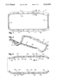
- FIG. 1 is a bottom plan view of an oil pan gasket assembly in accordance with the present invention
- FIG. 2 is a bottom perspective view of the oil pan gasket assembly of FIG. 1;
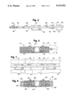
- FIG. 3 is a plan view of the rails incorporated in the gasket assembly of FIG. 1;
- FIG. 4 is a fragmentary side elevational view, partially in section, of a rail of FIG. 3;
- FIG. 5 is a cross-sectional view taken substantially along line 5--5 of FIG. 1;
- FIG. 6 is a cross-sectional view of a further embodiment of the present invention viewed from the same location as that of FIG. 5;
- FIG. 7 is a fragmentary side elevational view of a rail like that of FIG. 3 shown as supported in a mold in an alternative manner.
- FIG. 1 shows a gasket assembly 10 formed for use as an oil pan gasket.
- Gasket assembly 10 comprises a pair of generally elongate, relatively stiff side portions or sections 12, 14, and a pair of concave or arched end sections 16, 18.
- Each of the side sections 12, 14 defines a plurality of fastener openings and comprises a stiff rail 20, 22, respectively, embedded within a molded elastomeric or rubber sheath 24, 26, respectively.
- the elastomer may vary and may desirably be nitrile, polyacrylic or silicone rubber.
- the end sections 16, 18 are also of a molded elastomer.
- the sheaths 24, 26 and end sections 16, 18 are preferably integrally molded and are joined at their respective ends.
- Each of the rails is integrally molded and is configured to the particular gasket construction.
- a preferred rail is plastic, and preferably a thermoplastic material such as a glass filled nylon material comprising about 33% glass fibers and 67% nylon.
- a suitable nylon is Nylon 6/6, obtained from Hoechst Celanese Corporation under the designation NY/M1503.
- Another suitable rail material comprises filled polyphenylene sulfide having about 40% glass fibers and 60% polyphenylene sulfide, such as one obtained from LNP Corporation under the designation Thermocomp OF-1008.
- the glass fibers used may be short, medium or long.
- Each of the rails provides a number of formations which project from the major surfaces, the upper and lower surfaces thereof, and which are integrally formed therewith.
- each of the rails has a generally flat main body 30 of a first, generally uniform thickness.
- Each rail further is provided with a plurality of longitudinally spaced compression stops 32. Stops 32 project both upwardly and downwardly from main body 30 and are, as may be seen, substantially greater in thickness from top to bottom, than the thickness of the main body, and desirably by a factor of at least three.
- Each of the stops 32, together with the main body 30, defines an opening 34 through which an associated fastener may pass. Because the purpose of the stops 32 is to control and limit the degree of compression of the gasket overall, and especially in the zones of the side sections, while permitting compression of the associated elastomer sheaths to effect sealing, they are of a lesser thickness than the sheaths.
- the rails also define and include a number of other elements. These include a plurality of apertures 36 which are positioned along the length of the rails. Apertures 36 are provided so that during molding material may pass therethrough to integrate the rail with the elastomer sheath of the associated side section.
- the rails also include a plurality of spaced projecting members and abutments along the length of the rail for appropriately positioning each rail in its associated side section. These include a plurality of projections 38 which extend from one surface of the rail between the stops and more particularly between each pair of adjacent apertures 36. These help insure that the elastomer will flow through the apertures 36 during the molding process and that the thickness of the elastomer sheath at that surface of the rail will be correctly provided during molding. Additional abutments include several pairs of projections 40, 42 which extend from opposite surfaces of the rail adjacent edges of those surfaces. The abutments of each pair may be of different heights, as best seen in FIG. 4. The heights of projections 40, 42 are generally the same as the corresponding projecting portions of the stops 32. These projections 40, 42 provide standoffs which assist in the molding process to make certain that the rubber sheaths are molded to the desired dimensions.
- abutments or directors 44, 46 project from opposite surfaces of each rail at spaced locations. These are generally V-shaped and preferably confront the zones at which elastomer is directed into the mold to form the elastomeric sheaths. They assist in directing the molten elastomer flow to insure proper and complete filling of the mold.
- the director 44 may be of generally the same height as the similarly projecting portion of the stop 32, whereas the director 46 may be much less in height than the corresponding projecting portion of the stop 32 where it is somewhat less critical to control the rubber thickness as closely.
- the abutments and projections perform important functions in providing properly formed elastomeric sheaths which will suitably seal along the confronting flanges of the engine parts to be sealed and to help control, as well, the degree to which the stops 32 will be recessed below the surfaces of the elastomeric sheaths in accordance with the designed respective thicknesses.
- abutments 40, 42, 44, 46 may be provided. Although in some circumstances the abutments as illustrated may be sufficient to prevent the rails from becoming deformed under the molding pressures used, in other situations the molding pressures may tend to distort the rails, hence cause undesired variations in thickness in the elastomeric sheathing.
- mold surfaces M shown in dotted line. These mold surfaces serve to clamp the rail edge during molding to hold the rail centered. Although only one such edge is shown as being so clamped in FIG. 5, it is apparent that both edges may be so clamped by appropriate mold surfaces.
- FIG. 7 is like FIG. 4, but rather than having abutments, such as projections and directors 40, 42, 44, 46 (although it may retain such also if desired), FIG. 7 illustrates the rail as being retained during molding in a centered portion by pins P provided on the mold surfaces M'.
- the pins P preferably project upwardly and downwardly between each pair of spaced compression stops 32.
- supplemental longitudinally extending sealing beads 48, 50 may be provided as well. Like similar beads as used in the past, these help provide the most effective seal when the gasket assembly 10 of this invention is used.
- FIG. 6 The embodiment of FIG. 6 is similar to that of FIGS. 1-5. Accordingly the same part numbers have been used. The principal difference is that means are provided for stiffening the rails, hence the gasket assembly respective side sections.
- the side section 12' includes a rail 20' which has a main body portion 30', a stop 32', a stop opening 34' and an elastomeric sheath including longitudinally extending sealing beads 48', 50'.
- the apertures, abutments and projections described above relative to the embodiment of FIGS. 1-5 are used as well, except that projections 40, 42 and directors 44, 46 may not be necessary or present.
- rail 20' includes at least one stiffening rib projecting from a major surface of the rail at a right angle thereto adjacent an edge of the rail surface.
- the projecting stiffening ribs in the FIG. 6 embodiment includes two pairs of such stiffening ribs. Each pair includes projecting rib elements 60, 62 which projects upwardly and downwardly at the edge of the adjacent surfaces.
- the stiffening ribs extend along at least the substantial lengths of the rail edges.
- the heights of the ribs are substantially the same as those of the projecting portions of the stops 32'. Thus, they both stiffen, but do not interfere with the compression stopping function of the stops 32'. They may assist in this function adjacent the zones of the stops or they may be slightly reduced in height at those zones so that they do not, under any normal circumstances of use, assist in the compression controlling function of stops 32'.
- a greatly improved and highly advantageous gasket assembly is provided. It substantially reduces the cost of such a gasket assembly, by reducing material cost, assembly time and cost and by reducing processing time. It eliminates inspection time and very importantly insures that the gasket will be correctly assembled with the required compression control being provided with certainty at each location where it is desired.
- the gasket assembly is easily installed and seals in a highly effective manner. When the stiffening ribs are used, the gasket assembly is even easier to handle and to install than are the available prior art gaskets.
Landscapes
- Engineering & Computer Science (AREA)
- General Engineering & Computer Science (AREA)
- Mechanical Engineering (AREA)
- Gasket Seals (AREA)
- Lubrication Details And Ventilation Of Internal Combustion Engines (AREA)
Abstract
Description
Claims (4)
Priority Applications (5)
| Application Number | Priority Date | Filing Date | Title |
|---|---|---|---|
| US07/610,100 US5121932A (en) | 1990-11-07 | 1990-11-07 | Gasket assembly for oil pans and the like |
| EP91118658A EP0485815B1 (en) | 1990-11-07 | 1991-10-31 | Gasket assembly for oil pans and the like |
| ES91118658T ES2069174T3 (en) | 1990-11-07 | 1991-10-31 | GASKET SET FOR OIL AND SIMILAR CARTERS. |
| DE69107578T DE69107578T2 (en) | 1990-11-07 | 1991-10-31 | Seal for oil pan and the like. |
| JP3350595A JPH0811979B2 (en) | 1990-11-07 | 1991-11-07 | Oil pan and similar gasket assembly |
Applications Claiming Priority (1)
| Application Number | Priority Date | Filing Date | Title |
|---|---|---|---|
| US07/610,100 US5121932A (en) | 1990-11-07 | 1990-11-07 | Gasket assembly for oil pans and the like |
Publications (1)
| Publication Number | Publication Date |
|---|---|
| US5121932A true US5121932A (en) | 1992-06-16 |
Family
ID=24443646
Family Applications (1)
| Application Number | Title | Priority Date | Filing Date |
|---|---|---|---|
| US07/610,100 Expired - Lifetime US5121932A (en) | 1990-11-07 | 1990-11-07 | Gasket assembly for oil pans and the like |
Country Status (5)
| Country | Link |
|---|---|
| US (1) | US5121932A (en) |
| EP (1) | EP0485815B1 (en) |
| JP (1) | JPH0811979B2 (en) |
| DE (1) | DE69107578T2 (en) |
| ES (1) | ES2069174T3 (en) |
Cited By (18)
| Publication number | Priority date | Publication date | Assignee | Title |
|---|---|---|---|---|
| US5492343A (en) * | 1994-03-04 | 1996-02-20 | Federal-Mogul Corporation | Gasket assembly |
| US5513603A (en) * | 1995-08-11 | 1996-05-07 | Chrysler Corporation | Seal and fastener isolator system for a valve cover |
| US5618047A (en) * | 1995-03-14 | 1997-04-08 | Dana Corporation | Molded gasket with a multiple component reinforcing element |
| US6039323A (en) * | 1998-02-11 | 2000-03-21 | Fel-Pro Incorporated | Rubber molded gasket with compression limiter |
| US6073937A (en) * | 1997-12-03 | 2000-06-13 | Caterpillar Inc. | Composite top plate for a fluid filter and an associated method for forming a composite top plate adapted for attachment to a fluid filter |
| US6406033B1 (en) * | 1997-10-14 | 2002-06-18 | Filterwerk Mann & Hummel Gmbh | Sealing element |
| US6609717B2 (en) * | 2001-10-09 | 2003-08-26 | Dana Corporation | Thermoplastic gasket with edge bonded rubber apertures and integral alignment grommets |
| US6676135B2 (en) * | 2002-04-03 | 2004-01-13 | General Motors Corporation | Oil transfer seal assembly |
| US20060097458A1 (en) * | 2004-11-09 | 2006-05-11 | Federal-Mogul World Wide, Inc. | Gasket assembly |
| US20060157939A1 (en) * | 2004-01-12 | 2006-07-20 | Beutler Kevin R | Axle differential with stamped carrier cover pan |
| US7407165B1 (en) | 2000-04-04 | 2008-08-05 | Hutchinson Fts, Inc. | Composite sleeve for sealing a tubular coupling |
| US20110095492A1 (en) * | 2008-07-17 | 2011-04-28 | Yasumaro Takeda | Cylinder head gasket |
| US20140138917A1 (en) * | 2012-11-21 | 2014-05-22 | Bill Sieff | One Piece Oil Pan Gasket |
| DE102013209229A1 (en) * | 2013-05-17 | 2014-11-20 | Elringklinger Ag | Sealing device and valve cover |
| US20160010521A1 (en) * | 2013-06-27 | 2016-01-14 | Uchiyama Manufacturing Corp. | Oil pan |
| US11199228B2 (en) * | 2018-07-03 | 2021-12-14 | Dodge Acquisition Co. | Grid coupling seal and method |
| US11235964B2 (en) * | 2018-04-27 | 2022-02-01 | Aktiebolaget Skf | Sealing system for food applications |
| US12132222B2 (en) | 2019-12-02 | 2024-10-29 | Lg Energy Solution, Ltd. | Battery pack and device including the same |
Families Citing this family (5)
| Publication number | Priority date | Publication date | Assignee | Title |
|---|---|---|---|---|
| US5536023A (en) * | 1994-10-31 | 1996-07-16 | Indian Head Industries, Inc. | One piece gasket for complex oil pan configuration |
| JP2001271935A (en) * | 2000-03-24 | 2001-10-05 | Nippon Gasket Co Ltd | Gasket tightening structure |
| FR2871210B1 (en) * | 2004-06-07 | 2006-10-06 | Meillor Sa Sa | SEALING JOINT INCORPORATING A FOAM OR ANALOGUE COATING AND A SQUEEZING LIMITING DEVICE THEREOF |
| DE102008053328A1 (en) * | 2008-10-27 | 2010-04-29 | Ibs Filtran Kunststoff-/ Metallerzeugnisse Gmbh | Sealing frame carrier for use in constructional unit for connecting oil sump with transmission housing or engine housing of motor vehicle, is fastened over fastening points in detachable or undetachable manner and formed of metal |
| JP6941515B2 (en) * | 2017-09-14 | 2021-09-29 | 株式会社清水合金製作所 | Gasket with overcompression prevention structure and its manufacturing method |
Citations (17)
| Publication number | Priority date | Publication date | Assignee | Title |
|---|---|---|---|---|
| DE223399C (en) * | ||||
| DE1137199B (en) * | 1956-09-08 | 1962-09-27 | Guenter Pollehne | Composite body, consisting of polystyrene foam and a sheet metal support |
| US3565449A (en) * | 1968-12-06 | 1971-02-23 | Felt Products Mfg Co | Head gasket assembly having parts therein |
| US4072316A (en) * | 1976-11-26 | 1978-02-07 | Eagle-Picher Industries, Inc. | Three-piece heat resistant gasket |
| US4203941A (en) * | 1978-12-27 | 1980-05-20 | Brooker Bernard F | Ball and method for making it |
| US4234638A (en) * | 1976-07-23 | 1980-11-18 | Nippon Carbon Co., Ltd. | Composite graphite sheets |
| JPS5756209A (en) * | 1980-04-11 | 1982-04-03 | Eisuke Musha | Method of providing rubber or plastic projections on both sides of plate having many therough-holes |
| US4373735A (en) * | 1978-09-15 | 1983-02-15 | Goetze Ag | Soft material sealing disc used as head gasket |
| US4485138A (en) * | 1981-12-16 | 1984-11-27 | Nichias Corporation | Heat-resistant sheet gasket |
| US4535996A (en) * | 1985-01-18 | 1985-08-20 | Felt Products Mfg. Co. | Gasket assembly for oil pans and the like and method of making same |
| US4652415A (en) * | 1985-02-11 | 1987-03-24 | General Motors Corporation | Method of manufacture of a molded friction pad |
| US4655463A (en) * | 1986-09-05 | 1987-04-07 | Felt Products Mfg. Co. | Gasket assembly for oil pan valve covers and the like |
| US4705278A (en) * | 1986-09-29 | 1987-11-10 | Fel-Pro Incorporated | Selectively compressed expanded graphite gasket and method of making same |
| US4824627A (en) * | 1985-11-18 | 1989-04-25 | Floyd V. Hammer | Method of making a molded plastic product |
| US4876915A (en) * | 1986-08-09 | 1989-10-31 | Toyoda Gosei Co., Ltd. | Steering wheel |
| US4955621A (en) * | 1989-09-22 | 1990-09-11 | Jpi Transportation Products, Inc. | Gasket |
| US4997193A (en) * | 1990-05-18 | 1991-03-05 | Fel-Pro Incorporated | Oil pan gasket and method of making same |
Family Cites Families (1)
| Publication number | Priority date | Publication date | Assignee | Title |
|---|---|---|---|---|
| DE3831414A1 (en) * | 1988-09-15 | 1990-03-22 | Bruss Dichtungstechnik | Dimensionally stable rubber shaped gasket, particularly an oil-sump or cylinder-head cover gasket, for an internal combustion engine |
-
1990
- 1990-11-07 US US07/610,100 patent/US5121932A/en not_active Expired - Lifetime
-
1991
- 1991-10-31 DE DE69107578T patent/DE69107578T2/en not_active Expired - Fee Related
- 1991-10-31 ES ES91118658T patent/ES2069174T3/en not_active Expired - Lifetime
- 1991-10-31 EP EP91118658A patent/EP0485815B1/en not_active Expired - Lifetime
- 1991-11-07 JP JP3350595A patent/JPH0811979B2/en not_active Expired - Fee Related
Patent Citations (17)
| Publication number | Priority date | Publication date | Assignee | Title |
|---|---|---|---|---|
| DE223399C (en) * | ||||
| DE1137199B (en) * | 1956-09-08 | 1962-09-27 | Guenter Pollehne | Composite body, consisting of polystyrene foam and a sheet metal support |
| US3565449A (en) * | 1968-12-06 | 1971-02-23 | Felt Products Mfg Co | Head gasket assembly having parts therein |
| US4234638A (en) * | 1976-07-23 | 1980-11-18 | Nippon Carbon Co., Ltd. | Composite graphite sheets |
| US4072316A (en) * | 1976-11-26 | 1978-02-07 | Eagle-Picher Industries, Inc. | Three-piece heat resistant gasket |
| US4373735A (en) * | 1978-09-15 | 1983-02-15 | Goetze Ag | Soft material sealing disc used as head gasket |
| US4203941A (en) * | 1978-12-27 | 1980-05-20 | Brooker Bernard F | Ball and method for making it |
| JPS5756209A (en) * | 1980-04-11 | 1982-04-03 | Eisuke Musha | Method of providing rubber or plastic projections on both sides of plate having many therough-holes |
| US4485138A (en) * | 1981-12-16 | 1984-11-27 | Nichias Corporation | Heat-resistant sheet gasket |
| US4535996A (en) * | 1985-01-18 | 1985-08-20 | Felt Products Mfg. Co. | Gasket assembly for oil pans and the like and method of making same |
| US4652415A (en) * | 1985-02-11 | 1987-03-24 | General Motors Corporation | Method of manufacture of a molded friction pad |
| US4824627A (en) * | 1985-11-18 | 1989-04-25 | Floyd V. Hammer | Method of making a molded plastic product |
| US4876915A (en) * | 1986-08-09 | 1989-10-31 | Toyoda Gosei Co., Ltd. | Steering wheel |
| US4655463A (en) * | 1986-09-05 | 1987-04-07 | Felt Products Mfg. Co. | Gasket assembly for oil pan valve covers and the like |
| US4705278A (en) * | 1986-09-29 | 1987-11-10 | Fel-Pro Incorporated | Selectively compressed expanded graphite gasket and method of making same |
| US4955621A (en) * | 1989-09-22 | 1990-09-11 | Jpi Transportation Products, Inc. | Gasket |
| US4997193A (en) * | 1990-05-18 | 1991-03-05 | Fel-Pro Incorporated | Oil pan gasket and method of making same |
Cited By (23)
| Publication number | Priority date | Publication date | Assignee | Title |
|---|---|---|---|---|
| US5492343A (en) * | 1994-03-04 | 1996-02-20 | Federal-Mogul Corporation | Gasket assembly |
| US5618047A (en) * | 1995-03-14 | 1997-04-08 | Dana Corporation | Molded gasket with a multiple component reinforcing element |
| US5513603A (en) * | 1995-08-11 | 1996-05-07 | Chrysler Corporation | Seal and fastener isolator system for a valve cover |
| US6406033B1 (en) * | 1997-10-14 | 2002-06-18 | Filterwerk Mann & Hummel Gmbh | Sealing element |
| US6073937A (en) * | 1997-12-03 | 2000-06-13 | Caterpillar Inc. | Composite top plate for a fluid filter and an associated method for forming a composite top plate adapted for attachment to a fluid filter |
| US6039323A (en) * | 1998-02-11 | 2000-03-21 | Fel-Pro Incorporated | Rubber molded gasket with compression limiter |
| US7407165B1 (en) | 2000-04-04 | 2008-08-05 | Hutchinson Fts, Inc. | Composite sleeve for sealing a tubular coupling |
| US6609717B2 (en) * | 2001-10-09 | 2003-08-26 | Dana Corporation | Thermoplastic gasket with edge bonded rubber apertures and integral alignment grommets |
| US6676135B2 (en) * | 2002-04-03 | 2004-01-13 | General Motors Corporation | Oil transfer seal assembly |
| US20060157939A1 (en) * | 2004-01-12 | 2006-07-20 | Beutler Kevin R | Axle differential with stamped carrier cover pan |
| US7070187B2 (en) * | 2004-11-09 | 2006-07-04 | Federal-Mogul World Wide, Inc | Gasket assembly |
| US20060097458A1 (en) * | 2004-11-09 | 2006-05-11 | Federal-Mogul World Wide, Inc. | Gasket assembly |
| US20110095492A1 (en) * | 2008-07-17 | 2011-04-28 | Yasumaro Takeda | Cylinder head gasket |
| US8960681B2 (en) * | 2008-07-17 | 2015-02-24 | Nippon Gasket Co., Ltd. | Cylinder head gasket |
| US20140138917A1 (en) * | 2012-11-21 | 2014-05-22 | Bill Sieff | One Piece Oil Pan Gasket |
| DE102013209229A1 (en) * | 2013-05-17 | 2014-11-20 | Elringklinger Ag | Sealing device and valve cover |
| US20160010521A1 (en) * | 2013-06-27 | 2016-01-14 | Uchiyama Manufacturing Corp. | Oil pan |
| US9840950B2 (en) * | 2013-06-27 | 2017-12-12 | Toyota Jidosha Kabushiki Kaisha | Oil pan |
| US11235964B2 (en) * | 2018-04-27 | 2022-02-01 | Aktiebolaget Skf | Sealing system for food applications |
| US11199228B2 (en) * | 2018-07-03 | 2021-12-14 | Dodge Acquisition Co. | Grid coupling seal and method |
| US20220056961A1 (en) * | 2018-07-03 | 2022-02-24 | Dodge Acquisition Co. | Grid coupling seal and method |
| US11592065B2 (en) * | 2018-07-03 | 2023-02-28 | Dodge Industrial, Inc. | Grid coupling seal and method |
| US12132222B2 (en) | 2019-12-02 | 2024-10-29 | Lg Energy Solution, Ltd. | Battery pack and device including the same |
Also Published As
| Publication number | Publication date |
|---|---|
| EP0485815A2 (en) | 1992-05-20 |
| ES2069174T3 (en) | 1995-05-01 |
| JPH0811979B2 (en) | 1996-02-07 |
| DE69107578T2 (en) | 1995-10-19 |
| DE69107578D1 (en) | 1995-03-30 |
| EP0485815A3 (en) | 1992-06-03 |
| EP0485815B1 (en) | 1995-02-22 |
| JPH05172252A (en) | 1993-07-09 |
Similar Documents
| Publication | Publication Date | Title |
|---|---|---|
| US5121932A (en) | Gasket assembly for oil pans and the like | |
| US5536018A (en) | Flexible spaghetti gasket seal with stiffening member | |
| US6210266B1 (en) | Pressure relief valve and method of manufacturing the same | |
| US5267740A (en) | Metal head gasket with integrated sealing aids | |
| US5511518A (en) | Sealing assembly with undercut groove | |
| US5639993A (en) | Grommet | |
| US6135418A (en) | Low-leakage air valve for variable air intake system | |
| US20040000763A1 (en) | Molded gasket | |
| US5551705A (en) | Double beaded spaghetti seal with stiffness increasing deformation behavior | |
| US5618047A (en) | Molded gasket with a multiple component reinforcing element | |
| KR870009833A (en) | Gasket forming mold of window assembly | |
| US3936059A (en) | Sealing boundary gasket for compression between flanged portions of two mating metal members | |
| EP0270287B1 (en) | Gasket seal | |
| US6213077B1 (en) | Resonator type silencer for automotive engine | |
| EP1415101B1 (en) | Appliance with seal between two housing shells | |
| US6173966B1 (en) | T-joint gasket assembly | |
| US5275420A (en) | End seals for V-type internal combustion engines and engine sealing method | |
| US4955621A (en) | Gasket | |
| SE438538B (en) | SEAL FOR A SHUTTER VALVE | |
| KR890010151A (en) | Angled joint sealing structure | |
| GB2327242A (en) | A cover assembly for closing across an opening in a panel | |
| US20040173974A1 (en) | Seal feature to prevent bending | |
| US4226428A (en) | Flexible seal and groove assembly | |
| US5181698A (en) | Hydraulically damping rubber bearing | |
| US20070262537A1 (en) | Method for the Production of a Flat Seal, and Flat Seal |
Legal Events
| Date | Code | Title | Description |
|---|---|---|---|
| AS | Assignment |
Owner name: FEL-PRO INCORPORATED, AN IL CORP. Free format text: ASSIGNMENT OF ASSIGNORS INTEREST.;ASSIGNORS:GOLDMAN, ROBERT B.;HENHAPL, ALBERT;ADELIZZI, MARK J.;REEL/FRAME:005529/0693 Effective date: 19901031 |
|
| STCF | Information on status: patent grant |
Free format text: PATENTED CASE |
|
| FEPP | Fee payment procedure |
Free format text: PAYOR NUMBER ASSIGNED (ORIGINAL EVENT CODE: ASPN); ENTITY STATUS OF PATENT OWNER: LARGE ENTITY |
|
| FPAY | Fee payment |
Year of fee payment: 4 |
|
| FEPP | Fee payment procedure |
Free format text: PAYOR NUMBER ASSIGNED (ORIGINAL EVENT CODE: ASPN); ENTITY STATUS OF PATENT OWNER: LARGE ENTITY |
|
| FEPP | Fee payment procedure |
Free format text: PAYER NUMBER DE-ASSIGNED (ORIGINAL EVENT CODE: RMPN); ENTITY STATUS OF PATENT OWNER: LARGE ENTITY |
|
| FPAY | Fee payment |
Year of fee payment: 8 |
|
| AS | Assignment |
Owner name: WILMINGTON TRUST COMPANY, AS TRUSTEE, DELAWARE Free format text: SECURITY AGREEMENT;ASSIGNOR:FEDERAL-MOGUL WORLD WIDE, INC. (MI CORPORATION);REEL/FRAME:011571/0001 Effective date: 20001229 |
|
| FPAY | Fee payment |
Year of fee payment: 12 |
|
| AS | Assignment |
Owner name: FEDERAL-MOGUL WORLDWIDE, INC., MICHIGAN Free format text: RELEASE OF SECURITY INTEREST RECORDED AT REEL/FRAME 011571/0001 AND 011466/0001;ASSIGNOR:WILMINGTON TRUST COMPANY, AS TRUSTEE;REEL/FRAME:020299/0377 Effective date: 20071217 |
|
| AS | Assignment |
Owner name: CITIBANK, N.A. AS COLLATERAL TRUSTEE, NEW YORK Free format text: SECURITY AGREEMENT;ASSIGNOR:FEDERAL-MOGUL WORLD WIDE, INC.;REEL/FRAME:020431/0075 Effective date: 20071227 |