US51183A - Improvement in pumps - Google Patents
Improvement in pumps Download PDFInfo
- Publication number
- US51183A US51183A US51183DA US51183A US 51183 A US51183 A US 51183A US 51183D A US51183D A US 51183DA US 51183 A US51183 A US 51183A
- Authority
- US
- United States
- Prior art keywords
- stock
- pen
- pump
- chamber
- water
- Prior art date
- Legal status (The legal status is an assumption and is not a legal conclusion. Google has not performed a legal analysis and makes no representation as to the accuracy of the status listed.)
- Expired - Lifetime
Links
- XLYOFNOQVPJJNP-UHFFFAOYSA-N water Substances O XLYOFNOQVPJJNP-UHFFFAOYSA-N 0.000 description 9
- 238000010276 construction Methods 0.000 description 2
- 230000000994 depressogenic effect Effects 0.000 description 2
- 230000000881 depressing effect Effects 0.000 description 1
- 238000007599 discharging Methods 0.000 description 1
- 239000010985 leather Substances 0.000 description 1
- 239000000463 material Substances 0.000 description 1
- 239000002184 metal Substances 0.000 description 1
- 238000012856 packing Methods 0.000 description 1
Images

Classifications
-
- F—MECHANICAL ENGINEERING; LIGHTING; HEATING; WEAPONS; BLASTING
- F02—COMBUSTION ENGINES; HOT-GAS OR COMBUSTION-PRODUCT ENGINE PLANTS
- F02M—SUPPLYING COMBUSTION ENGINES IN GENERAL WITH COMBUSTIBLE MIXTURES OR CONSTITUENTS THEREOF
- F02M59/00—Pumps specially adapted for fuel-injection and not provided for in groups F02M39/00 -F02M57/00, e.g. rotary cylinder-block type of pumps
- F02M59/44—Details, components parts, or accessories not provided for in, or of interest apart from, the apparatus of groups F02M59/02 - F02M59/42; Pumps having transducers, e.g. to measure displacement of pump rack or piston
Definitions
- This invention consists in constructing a force -pump with a hollow discharging piston or plunger having a Valve in its bottom opening upward and a discharge-pi pe at its top, and combining such a plunger with a vessel having an open top in such manner that when the plunger is elevated to its fullest extent the top of the vessel will be exposed to receive water, and when the plunger is again depressed this water will be forced into it and through the dischargepipe, as will be hereinafter described.
- My invention also consists in a novel mode of guiding and operating the plunger and cylvinuer of a pump, which has a reciprocating open-top cylinder and a discharging-piston, as will be hereinafter described.
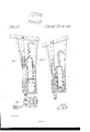
- A represents the pen-stock, which may be made cylindrical or square. I prefer to construct it, as represented in the drawings, with a lower cylindrical portion terminating in an upper retangu larhead.
- This peirstock is made hollow, and it is provided with a valve, a, in its lower end, which opens upward, and a discharge-pipe, b, projecting from its upper end above the top of the well.v Ii' desirable, the lower end of the pen-stock may be provide-d with a packing, c, of leather or other suitable material.
- the cylindrical portion ol the pen-stock works in a chamber, B', which is made in a movable portion, B, somewhat after the manner of a piston and cylinder pump, but with this dili'erence: the chamber B' has no valves applied to it, and receives water from the well through its upper end, which is opened when the pen-stock is elevated to its fullest extent, as shown in Fig. l.
- the pen-stock works snuglyin the chamber B, and when it is raised above the upper end thereof ⁇ the extensions e e of the portion B keep the pen-stock in a proper position to enter the chamber B again.
- the pen-stock A When the pen-stock A is elevated, as will be hereinafter explained, it forms a partial vacuum in the chamber B', and as this cham ber should be submerged in the water of the well, the water will rush rapidly7 into the chamber and iill it. Then upon depressing the penstock the water in said chamber will be forced through the valve-opening in the pen-stock and up through the discharge-pipe b. Vhen the pen-stock ceases to descend the valve a will" be suddenly7 closed by the weight of the ⁇ column ot' water above it.
- the pen-stock A and the chambered portion B are both constructed with grooved extensions ff', which are received and guided by the vertical slot, g, through the supporting-beam D, as shown in Figs. l and 2.
- This beam is suitably arranged within the well and secured therein in a vertical position, so as to constitute a support as well as a guide for the working parts of the pump.
- the lever E is pivoted to the upper end of the supporting-beam D, at i, and the extremity of the short arm ot' this lever or pump-handle is pivoted to a rod, F, the lower end of which is rigidly secured to the chambered portion B, as shown in Figs. l and 2.
- the pen-stock A is connected to the long arm of lever F by means of a rod, Gr', which is pivoted at one end to said lever and secured rigidly at the other end to the pen-stock.
- the beam D serves as a fulcrum for the pumplever E, and also as a guide for keeping the axis ofthe pen-stock always coincident with that ot' the chamber within which it works.
- One of the chief objects ot' my invention is to so contrive a force-pump having but one valve that it can be easily and cheaply made by an ordinary carpenter.
Landscapes
- Engineering & Computer Science (AREA)
- Chemical & Material Sciences (AREA)
- Combustion & Propulsion (AREA)
- Mechanical Engineering (AREA)
- General Engineering & Computer Science (AREA)
- Reciprocating Pumps (AREA)
Description
PATENT OFFICE..
J. Gr. HOVEY, OF VAVERLY, IOIVA.
IMPROVEMENT IN PUMPS.
pecilication forming part of Letters Patent N0. 51,183, datedNovelnber 28, 1865.
l To all whoa; it may concern:
Be it known that I, J. G. HOVEY, of Wa verly, in ,the county ot' Bremer and State of Iowa', have invented a new and Improved Pump; and I do hereby declare that the followingis afull, clear, and exact description there of, reference being had to the accompanying drawings, making a part of this specification, in which- Figure 1 is a vertical elevation and section through my improved pump, representingthe plunger in an elevated position. Fig. 2 is a similar view representing the plunger in a depressed position. Fig. 3 is a section through the pump taken in the horizontal plane indicated by red line a' x.
Similar letters of reference indicate corresponding parts in the several figures.
This invention consists in constructing a force -pump with a hollow discharging piston or plunger having a Valve in its bottom opening upward and a discharge-pi pe at its top, and combining such a plunger with a vessel having an open top in such manner that when the plunger is elevated to its fullest extent the top of the vessel will be exposed to receive water, and when the plunger is again depressed this water will be forced into it and through the dischargepipe, as will be hereinafter described.
My invention also consists in a novel mode of guiding and operating the plunger and cylvinuer of a pump, which has a reciprocating open-top cylinder and a discharging-piston, as will be hereinafter described.
To enable others skilled in the art to understand my invention, I will describe its construction and operation.
In the accompanying drawings, A represents the pen-stock, which may be made cylindrical or square. I prefer to construct it, as represented in the drawings, with a lower cylindrical portion terminating in an upper retangu larhead. This peirstock is made hollow, and it is provided with a valve, a, in its lower end, which opens upward, and a discharge-pipe, b, projecting from its upper end above the top of the well.v Ii' desirable, the lower end of the pen-stock may be provide-d with a packing, c, of leather or other suitable material.
The cylindrical portion ol the pen-stock works in a chamber, B', which is made in a movable portion, B, somewhat after the manner of a piston and cylinder pump, but with this dili'erence: the chamber B' has no valves applied to it, and receives water from the well through its upper end, which is opened when the pen-stock is elevated to its fullest extent, as shown in Fig. l. The pen-stock works snuglyin the chamber B, and when it is raised above the upper end thereof` the extensions e e of the portion B keep the pen-stock in a proper position to enter the chamber B again.
When the pen-stock A is elevated, as will be hereinafter explained, it forms a partial vacuum in the chamber B', and as this cham ber should be submerged in the water of the well, the water will rush rapidly7 into the chamber and iill it. Then upon depressing the penstock the water in said chamber will be forced through the valve-opening in the pen-stock and up through the discharge-pipe b. Vhen the pen-stock ceases to descend the valve a will" be suddenly7 closed by the weight of the` column ot' water above it. The pen-stock A and the chambered portion B are both constructed with grooved extensions ff', which are received and guided by the vertical slot, g, through the supporting-beam D, as shown in Figs. l and 2. This beam is suitably arranged within the well and secured therein in a vertical position, so as to constitute a support as well as a guide for the working parts of the pump. The lever E is pivoted to the upper end of the supporting-beam D, at i, and the extremity of the short arm ot' this lever or pump-handle is pivoted to a rod, F, the lower end of which is rigidly secured to the chambered portion B, as shown in Figs. l and 2.
The pen-stock A is connected to the long arm of lever F by means of a rod, Gr', which is pivoted at one end to said lever and secured rigidly at the other end to the pen-stock. By thus connecting the parts A and B to the lever E, it will be seen that they will alternately approach and recede from each other when the lever is vibrated, hence these parts need not be moved more than half the distance to give full strokes to them, which it would require it' only one of them moved.
The beam D serves as a fulcrum for the pumplever E, and also as a guide for keeping the axis ofthe pen-stock always coincident with that ot' the chamber within which it works.
One of the chief objects ot' my invention is to so contrive a force-pump having but one valve that it can be easily and cheaply made by an ordinary carpenter. There need not be any metal employed in its construction, consequently it will be found especially useful as a stock-pump to farmers and others, who can by my invention make their own pumps and keep them in good Working order for very little expense.
The provision which I make to move the pen-stock A and ehambered portion B simultaneously' iu opposite directions to each other is very important when employed in conjunction with the chamber B', which only receives Water at its upper end, as these parts can thus be kept submerged when the water of the Well is very low.
J. G. HOVEY.
Witnesses E. G. EVANS, Devin CLARK.
Publications (1)
| Publication Number | Publication Date |
|---|---|
| US51183A true US51183A (en) | 1865-11-28 |
Family
ID=2120733
Family Applications (1)
| Application Number | Title | Priority Date | Filing Date |
|---|---|---|---|
| US51183D Expired - Lifetime US51183A (en) | Improvement in pumps |
Country Status (1)
| Country | Link |
|---|---|
| US (1) | US51183A (en) |
-
0
- US US51183D patent/US51183A/en not_active Expired - Lifetime
Similar Documents
| Publication | Publication Date | Title |
|---|---|---|
| US51183A (en) | Improvement in pumps | |
| US32881A (en) | lewis | |
| US48401A (en) | Improvement in pumps | |
| US39974A (en) | Improvement in pumps | |
| US34101A (en) | Improvement in pumps | |
| US1135341A (en) | Tree-sprayer. | |
| US53750A (en) | Improvement in pumps | |
| US25642A (en) | William m | |
| US196953A (en) | Improvement in force-pumps | |
| US42417A (en) | Improvement in pumps | |
| US436708A (en) | William j | |
| US51028A (en) | Improvement in pumps | |
| US80617A (en) | Improvement in double-action pumps | |
| US50911A (en) | Improvement in pumps | |
| US200782A (en) | Improvement in pumps | |
| US32260A (en) | walter e | |
| US39842A (en) | Improvement in pumps | |
| US139003A (en) | Improvement in submerged force-pumps | |
| US174904A (en) | Imiprovement in force-pumps | |
| US42681A (en) | Improvement in pumps | |
| US44930A (en) | Improved apparatus for compressing air, gas | |
| US60098A (en) | wallis am | |
| US51686A (en) | Improvement in pumps | |
| US65684A (en) | Alexander moon | |
| US88538A (en) | Improvement in submerged pumps |