US5115834A - Valve-locking device - Google Patents
Valve-locking device Download PDFInfo
- Publication number
- US5115834A US5115834A US07/772,952 US77295291A US5115834A US 5115834 A US5115834 A US 5115834A US 77295291 A US77295291 A US 77295291A US 5115834 A US5115834 A US 5115834A
- Authority
- US
- United States
- Prior art keywords
- valve
- handle
- stem
- locking member
- locking device
- Prior art date
- Legal status (The legal status is an assumption and is not a legal conclusion. Google has not performed a legal analysis and makes no representation as to the accuracy of the status listed.)
- Expired - Fee Related
Links
- 239000012530 fluid Substances 0.000 claims abstract description 11
- 230000002093 peripheral effect Effects 0.000 claims description 4
- 230000007257 malfunction Effects 0.000 description 1
- 238000004519 manufacturing process Methods 0.000 description 1
- 238000000034 method Methods 0.000 description 1
- 238000012986 modification Methods 0.000 description 1
- 230000004048 modification Effects 0.000 description 1
Images


Classifications
-
- F—MECHANICAL ENGINEERING; LIGHTING; HEATING; WEAPONS; BLASTING
- F16—ENGINEERING ELEMENTS AND UNITS; GENERAL MEASURES FOR PRODUCING AND MAINTAINING EFFECTIVE FUNCTIONING OF MACHINES OR INSTALLATIONS; THERMAL INSULATION IN GENERAL
- F16K—VALVES; TAPS; COCKS; ACTUATING-FLOATS; DEVICES FOR VENTING OR AERATING
- F16K35/00—Means to prevent accidental or unauthorised actuation
- F16K35/06—Means to prevent accidental or unauthorised actuation using a removable actuating or locking member, e.g. a key
-
- Y—GENERAL TAGGING OF NEW TECHNOLOGICAL DEVELOPMENTS; GENERAL TAGGING OF CROSS-SECTIONAL TECHNOLOGIES SPANNING OVER SEVERAL SECTIONS OF THE IPC; TECHNICAL SUBJECTS COVERED BY FORMER USPC CROSS-REFERENCE ART COLLECTIONS [XRACs] AND DIGESTS
- Y10—TECHNICAL SUBJECTS COVERED BY FORMER USPC
- Y10T—TECHNICAL SUBJECTS COVERED BY FORMER US CLASSIFICATION
- Y10T137/00—Fluid handling
- Y10T137/7069—With lock or seal
- Y10T137/7256—Locks against rotary motion
-
- Y—GENERAL TAGGING OF NEW TECHNOLOGICAL DEVELOPMENTS; GENERAL TAGGING OF CROSS-SECTIONAL TECHNOLOGIES SPANNING OVER SEVERAL SECTIONS OF THE IPC; TECHNICAL SUBJECTS COVERED BY FORMER USPC CROSS-REFERENCE ART COLLECTIONS [XRACs] AND DIGESTS
- Y10—TECHNICAL SUBJECTS COVERED BY FORMER USPC
- Y10T—TECHNICAL SUBJECTS COVERED BY FORMER US CLASSIFICATION
- Y10T70/00—Locks
- Y10T70/50—Special application
- Y10T70/5611—For control and machine elements
- Y10T70/5615—Valve
- Y10T70/5619—Locked stationary
- Y10T70/5624—Externally mounted locking device
-
- Y—GENERAL TAGGING OF NEW TECHNOLOGICAL DEVELOPMENTS; GENERAL TAGGING OF CROSS-SECTIONAL TECHNOLOGIES SPANNING OVER SEVERAL SECTIONS OF THE IPC; TECHNICAL SUBJECTS COVERED BY FORMER USPC CROSS-REFERENCE ART COLLECTIONS [XRACs] AND DIGESTS
- Y10—TECHNICAL SUBJECTS COVERED BY FORMER USPC
- Y10T—TECHNICAL SUBJECTS COVERED BY FORMER US CLASSIFICATION
- Y10T70/00—Locks
- Y10T70/50—Special application
- Y10T70/5611—For control and machine elements
- Y10T70/5615—Valve
- Y10T70/5619—Locked stationary
- Y10T70/5637—With padlock
-
- Y—GENERAL TAGGING OF NEW TECHNOLOGICAL DEVELOPMENTS; GENERAL TAGGING OF CROSS-SECTIONAL TECHNOLOGIES SPANNING OVER SEVERAL SECTIONS OF THE IPC; TECHNICAL SUBJECTS COVERED BY FORMER USPC CROSS-REFERENCE ART COLLECTIONS [XRACs] AND DIGESTS
- Y10—TECHNICAL SUBJECTS COVERED BY FORMER USPC
- Y10T—TECHNICAL SUBJECTS COVERED BY FORMER US CLASSIFICATION
- Y10T70/00—Locks
- Y10T70/50—Special application
- Y10T70/5611—For control and machine elements
- Y10T70/5757—Handle, handwheel or knob
- Y10T70/5765—Rotary or swinging
- Y10T70/577—Locked stationary
- Y10T70/5774—Externally mounted locking device
- Y10T70/5779—With padlock
Definitions
- the present invention relates to a rotary valve for controlling fluid flow and a valve-locking device for use in association with such a rotary valve.
- rotary valves are utilized in situations where efficient cut-off or flow diversions are required in hydraulic systems.
- Locking devices are utilized for preventing unauthorized or inadvertent operation of the rotary valve.
- the selected operating position of a rotary valve is essential to the proper operation and functioning of the system and thus, the improper operation or positioning of the valve may result in a malfunction of the system which may result in dangerous and costly circumstances. Accordingly, it is desirable that rotary valves be provided with a locking device to prevent inadvertent or accidental movement of the operating handle as well as intentional tampering with the handle.
- Conventional locking devices have drawbacks in that the rotary valve cannot be operated without the removal of the locking device and the design of the locking device does not permit the handle to be mounted in a variety of rotational quadrants of the rotary valve. Additionally, conventional locking devices do not permit the rotary valve to be unlatched, rotary stroked and relatched smoothly with one hand.
- an object of the present invention is to provide for a novel rotary valve and locking device for the rotary valve in which the valve can be operated without removal of the locking device.
- a further object of the present invention is to provide for a rotary valve and a locking device in which the valve can be unlocked, rotary stroked and relocked smoothly with one hand.
- a further object of the present invention is to provide for a device in which the locking device can be mounted in any rotary quadrant of the rotary valve.
- a further object of the present invention is to provide for a locking device which remains part of the valve and accordingly there are no loose parts.
- a further object of the present invention is to provide for a locking device in which the handle strength of the operational handle on the rotary valve is unaffected by the valve locking device.
- the present invention provides for a rotary valve which comprises a valve body having a first bore therein for fluid flow.
- the valve body comprises a flange having a stop post; a stem extending into a second bore in the body; and control means for controlling fluid flow in the first bore of the valve body.
- the control means is operatively connected to the stem and is disposed in the first bore.
- a handle is mounted on the stem for operating the control means between opened and closed positions, the handle comprising an upwardly extending portion having a first hole therein.
- the rotary valve further comprises a valve locking member, the valve locking member defining a substantially L-shaped member.
- One leg of the L-shaped valve locking member defines a folded portion and comprises second and third holes which are aligned with each other.
- the other leg of the L-shaped valve locking member defines an opening.
- valve locking member of the present invention is positioned on the stem such that the stem extends through the opening of the other leg of the valve locking member.
- the handle is mounted on the stem above the valve locking member and the upwardly extending portion of the handle extends between the folded portion of the valve locking member.
- the valve locking member of the present invention is slidable between a locked position in which the first hole on the handle is aligned with the second and third holes on the folded portion of the valve locking member for permitting a lock means to pass between the first, second and third holes and an abutting surface of a periphery of the other leg of the valve locking member abuts against the stop post such that the handle is locked in a predetermined position; and an unlocked position in which the first hole is not aligned with the second and third holes and the abutting surface of the other leg of the valve locking member is spaced from the stop post for permitting movement of the handle.
- FIG. 1 is a perspective view of a rotary valve and a valve locking member mounted thereon of the present invention
- FIG. 2A is a perspective view of the valve locking member of the present invention.
- FIG. 2B is a top view of the valve locking member of FIG. 2A;
- FIG. 2C is a front view of the valve locking member of FIG. 2A;
- FIG. 2D is a side view of the valve locking member of FIG. 2A;
- FIG. 3A is a top view of the rotary valve and valve locking member of FIG. 1 showing the valve locking member in an unlocked position;
- FIG. 3B is a front view of FIG. 3A;
- FIG. 4 is a perspective view of the rotary valve and valve locking member in a locked position with a padlock extending therebetween and representing a first quadrant of operation of the rotary handle;
- FIG. 5A is a top view of the rotary valve and valve locking member as shown in FIG. 4;
- FIG. 5B is a front view of the rotary valve and valve locking member as shown in FIG. 5A;
- FIG. 6A is a top view of a locked rotary valve and valve locking member in a second quadrant of operation of the rotary handle;
- FIG. 6B is a front view of the rotary valve and valve locking member of FIG. 6A;
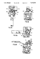
- FIG. 7A is a top view of a locked rotary handle and valve locking member in a third quadrant of operation of the rotary handle;
- FIG. 7B is a front view of the locked rotary valve and valve locking member of FIG. 7A;
- FIG. 8A is a top view of a locked rotary valve and valve locking member showing the rotary handle in a fourth quadrant of operation;
- FIG. 8B is a front view of the locked rotary valve and valve locking member of FIG. 8A.
- FIG. 1 illustrates a rotary valve 1 having a rotary body 3 and a flange portion 5 at a front end thereof.
- the flange portion 5 has a projecting stop post 7 which cooperates with a locking member 15 to lock the handle in a predetermined position.
- the interior of the rotary body 3 of the rotary valve 1 may contain any known control valve means 2 for controlling fluid flow passing through the openings 9(a) and 9(b) of the rotary valve.
- the control valve means 2 is operatively connected to a stem 11 (FIG. 3B) on which is mounted the locking member 15 and the handle 7. Both the locking member 15 and the handle 7 may be secured onto the stem through a stem nut 11a or other well known means.
- the rotary valve of the present invention can be operated by rotating the handle between any of the four quadrants as illustrated in FIGS. 5A, 6A, 7A and 8A in order to control the control valve 2 within the rotary valve 1 so as to selectively open and close the fluid flow passage through the rotary valve.
- the flow control valve 2 located within the rotary valve body 3 can be any known flow control valve such as for example a ball-type control valve.
- the locking member 15 of the present invention is illustrated in FIGS. 2A-2D and defines a substantially L-shaped member.
- the L-shaped member has a first leg 15a which defines a folded portion having aligned holes 17 and 18 (FIGS. 2A and 2D) and a second leg 15b defining an opening 19 and a peripheral surface 21 having abutting surfaces 21a, 21a', 21b and 21b'.
- the locking member 15 is positioned on the rotary valve 1 such that the stem 11 extends through the opening 19.
- the handle 7 which contains an aperture 25 on an upwardly extending portion 23 and a bore for cooperating with the stem 11 is positioned on stem 11 on top of the locking member 15.
- the upwardly extending portion 23 of the handle having the aperture 25 extends between an area 27 created by the folded portion 15a of the locking member 15.
- the locking member 15 can be moved away from the stop post 6 in order to permit the combination of the handle 7 and the locking member 15 to clear the stop post 6 and permit the rotation of the handle 7 and the control valve member 2 located inside the rotary body 3 to a desired position in order to either cut off or permit the flow of fluid through the rotary valve 1.
- the locking member 15 In a locked position as illustrated in FIG. 4, the locking member 15 is moved toward the stop post 6 so that the hole 25 in the extending portion 23 of the handle 7 is aligned with the holes 17 and 18 in the leg 15a of the locking member 15 and one of the abutting surfaces such as 21a of the locking member 15 can abut against the stop post 6 as illustrated in FIGS. 4-5.
- a padlock 30 or similar locking means can be passed through the aligned holes 17, 25 and 18 so as to lock the rotary valve in a desired position.
- FIGS. 4 and 5 show the rotary valve locked in a first quadrant such that the control valve 2 may be locked in an open position.
- FIGS. 5A and 5B further illustrate the handle and locking member locked in the above-mentioned first quadrant.
- the padlock is removed and the locking member 15 is moved as shown in FIGS. 3A and 3B so as to clear the stop 6.
- the handle 7 and locking member 15 can no be rotated into the second quadrant as shown in FIGS. 6A and 6B.
- the hole 25 in the extending portion 23 of the handle 7 is aligned with the holes 17 and 18 o the folded portion of the locking member 15 so as to enable a locking means such as the padlock 30 to be inserted through the aligned holes. In the position shown in FIG.
- one of the abutting surface such as 21b of the locking member 15 can abut against the stop post 6 in order to prevent the movement of the handle 7 from the second quadrant illustrated in FIGS. 6A and 6B. This enables the rotary valve to be maintained in for example an opened position.
- the handle can be easily rotated between the four quadrants without requiring the removal of the locking member. Additionally, the rotary valve can be unlocked, rotary stroked and relocked smoothly with one hand and the device can be mounted in any quadrant. Since the locking member and handle remain on the rotary valve, there are no loose parts. Additionally, since the locking member does not utilize and is not integral with the handle, the handle strength will not be affected.
Landscapes
- Engineering & Computer Science (AREA)
- General Engineering & Computer Science (AREA)
- Mechanical Engineering (AREA)
- Preventing Unauthorised Actuation Of Valves (AREA)
Abstract
A lever-operated rotary valve having a rotary body for permitting fluid flow therein includes a locking device for selectively locking and unlocking the operating handle such that the operating handle of the rotary valve can be locked in a plurality of predetermined positions. The operating handle of the rotary valve can be oriented in any one of a plurality of positions and locked in that position without requiring the removal of the locking device. The locking device is an L-shaped member which fits on the stem of the rotary valve and includes aligned holes for receiving a padlock so that the locking device and handle are locked together.
Description
1. Field of the Invention
The present invention relates to a rotary valve for controlling fluid flow and a valve-locking device for use in association with such a rotary valve.
2. Description of the Related Art
Conventionally, rotary valves are utilized in situations where efficient cut-off or flow diversions are required in hydraulic systems. Locking devices are utilized for preventing unauthorized or inadvertent operation of the rotary valve. In conventional fluid flow systems, the selected operating position of a rotary valve is essential to the proper operation and functioning of the system and thus, the improper operation or positioning of the valve may result in a malfunction of the system which may result in dangerous and costly circumstances. Accordingly, it is desirable that rotary valves be provided with a locking device to prevent inadvertent or accidental movement of the operating handle as well as intentional tampering with the handle.
Conventional locking devices are complex and difficult to manufacture and handle. Additionally, some conventional locking devices utilize a handle as part of the locking device.
Conventional locking devices have drawbacks in that the rotary valve cannot be operated without the removal of the locking device and the design of the locking device does not permit the handle to be mounted in a variety of rotational quadrants of the rotary valve. Additionally, conventional locking devices do not permit the rotary valve to be unlatched, rotary stroked and relatched smoothly with one hand.
Accordingly, an object of the present invention is to provide for a novel rotary valve and locking device for the rotary valve in which the valve can be operated without removal of the locking device.
A further object of the present invention is to provide for a rotary valve and a locking device in which the valve can be unlocked, rotary stroked and relocked smoothly with one hand.
A further object of the present invention is to provide for a device in which the locking device can be mounted in any rotary quadrant of the rotary valve.
A further object of the present invention is to provide for a locking device which remains part of the valve and accordingly there are no loose parts.
A further object of the present invention is to provide for a locking device in which the handle strength of the operational handle on the rotary valve is unaffected by the valve locking device.
The present invention provides for a rotary valve which comprises a valve body having a first bore therein for fluid flow. The valve body comprises a flange having a stop post; a stem extending into a second bore in the body; and control means for controlling fluid flow in the first bore of the valve body. The control means is operatively connected to the stem and is disposed in the first bore. A handle is mounted on the stem for operating the control means between opened and closed positions, the handle comprising an upwardly extending portion having a first hole therein. The rotary valve further comprises a valve locking member, the valve locking member defining a substantially L-shaped member. One leg of the L-shaped valve locking member defines a folded portion and comprises second and third holes which are aligned with each other. The other leg of the L-shaped valve locking member defines an opening.
The valve locking member of the present invention is positioned on the stem such that the stem extends through the opening of the other leg of the valve locking member. The handle is mounted on the stem above the valve locking member and the upwardly extending portion of the handle extends between the folded portion of the valve locking member.
The valve locking member of the present invention is slidable between a locked position in which the first hole on the handle is aligned with the second and third holes on the folded portion of the valve locking member for permitting a lock means to pass between the first, second and third holes and an abutting surface of a periphery of the other leg of the valve locking member abuts against the stop post such that the handle is locked in a predetermined position; and an unlocked position in which the first hole is not aligned with the second and third holes and the abutting surface of the other leg of the valve locking member is spaced from the stop post for permitting movement of the handle.
A more complete appreciation of the invention and many of the attendant advantages thereof will be readily obtained as the same becomes better understood by reference to the following detailed description when considered in connection with the accompanying drawings, wherein:
FIG. 1 is a perspective view of a rotary valve and a valve locking member mounted thereon of the present invention;
FIG. 2A is a perspective view of the valve locking member of the present invention;
FIG. 2B is a top view of the valve locking member of FIG. 2A;
FIG. 2C is a front view of the valve locking member of FIG. 2A;
FIG. 2D is a side view of the valve locking member of FIG. 2A;
FIG. 3A is a top view of the rotary valve and valve locking member of FIG. 1 showing the valve locking member in an unlocked position;
FIG. 3B is a front view of FIG. 3A;
FIG. 4 is a perspective view of the rotary valve and valve locking member in a locked position with a padlock extending therebetween and representing a first quadrant of operation of the rotary handle;
FIG. 5A is a top view of the rotary valve and valve locking member as shown in FIG. 4;
FIG. 5B is a front view of the rotary valve and valve locking member as shown in FIG. 5A;
FIG. 6A is a top view of a locked rotary valve and valve locking member in a second quadrant of operation of the rotary handle;
FIG. 6B is a front view of the rotary valve and valve locking member of FIG. 6A;
FIG. 7A is a top view of a locked rotary handle and valve locking member in a third quadrant of operation of the rotary handle;
FIG. 7B is a front view of the locked rotary valve and valve locking member of FIG. 7A;
FIG. 8A is a top view of a locked rotary valve and valve locking member showing the rotary handle in a fourth quadrant of operation;
FIG. 8B is a front view of the locked rotary valve and valve locking member of FIG. 8A.
Referring to the drawings, wherein like reference numerals designate identical or corresponding parts throughout the several views, and more particularly to FIG. 1 thereof, FIG. 1 illustrates a rotary valve 1 having a rotary body 3 and a flange portion 5 at a front end thereof. The flange portion 5 has a projecting stop post 7 which cooperates with a locking member 15 to lock the handle in a predetermined position.
The interior of the rotary body 3 of the rotary valve 1 may contain any known control valve means 2 for controlling fluid flow passing through the openings 9(a) and 9(b) of the rotary valve. The control valve means 2 is operatively connected to a stem 11 (FIG. 3B) on which is mounted the locking member 15 and the handle 7. Both the locking member 15 and the handle 7 may be secured onto the stem through a stem nut 11a or other well known means.
The rotary valve of the present invention can be operated by rotating the handle between any of the four quadrants as illustrated in FIGS. 5A, 6A, 7A and 8A in order to control the control valve 2 within the rotary valve 1 so as to selectively open and close the fluid flow passage through the rotary valve. The flow control valve 2 located within the rotary valve body 3 can be any known flow control valve such as for example a ball-type control valve.
The locking member 15 of the present invention is illustrated in FIGS. 2A-2D and defines a substantially L-shaped member. As illustrated in FIG. 2A, the L-shaped member has a first leg 15a which defines a folded portion having aligned holes 17 and 18 (FIGS. 2A and 2D) and a second leg 15b defining an opening 19 and a peripheral surface 21 having abutting surfaces 21a, 21a', 21b and 21b'.
In use, the locking member 15 is positioned on the rotary valve 1 such that the stem 11 extends through the opening 19. The handle 7 which contains an aperture 25 on an upwardly extending portion 23 and a bore for cooperating with the stem 11 is positioned on stem 11 on top of the locking member 15. When the handle 7 is positioned on the stem and on top of the locking member 15 as shown in FIG. 1, the upwardly extending portion 23 of the handle having the aperture 25 extends between an area 27 created by the folded portion 15a of the locking member 15.
In an unlocked position as shown in FIGS. 3A and 3B, due to the opening 19 of the locking member 15, the locking member 15 can be moved away from the stop post 6 in order to permit the combination of the handle 7 and the locking member 15 to clear the stop post 6 and permit the rotation of the handle 7 and the control valve member 2 located inside the rotary body 3 to a desired position in order to either cut off or permit the flow of fluid through the rotary valve 1.
In a locked position as illustrated in FIG. 4, the locking member 15 is moved toward the stop post 6 so that the hole 25 in the extending portion 23 of the handle 7 is aligned with the holes 17 and 18 in the leg 15a of the locking member 15 and one of the abutting surfaces such as 21a of the locking member 15 can abut against the stop post 6 as illustrated in FIGS. 4-5. In this position, a padlock 30 or similar locking means can be passed through the aligned holes 17, 25 and 18 so as to lock the rotary valve in a desired position.
For example, FIGS. 4 and 5 show the rotary valve locked in a first quadrant such that the control valve 2 may be locked in an open position. FIGS. 5A and 5B further illustrate the handle and locking member locked in the above-mentioned first quadrant.
If it is desired to lock the handle 7 and locking member 15 in a second quadrant as shown in FIGS. 6A and 6B, the padlock is removed and the locking member 15 is moved as shown in FIGS. 3A and 3B so as to clear the stop 6. The handle 7 and locking member 15 can no be rotated into the second quadrant as shown in FIGS. 6A and 6B. Once the handle 7 is in the second quadrant, the hole 25 in the extending portion 23 of the handle 7 is aligned with the holes 17 and 18 o the folded portion of the locking member 15 so as to enable a locking means such as the padlock 30 to be inserted through the aligned holes. In the position shown in FIG. 6A, one of the abutting surface such as 21b of the locking member 15 can abut against the stop post 6 in order to prevent the movement of the handle 7 from the second quadrant illustrated in FIGS. 6A and 6B. This enables the rotary valve to be maintained in for example an opened position.
The same procedure is applied in order to rotate and lock the operating handle in the third quadrant illustrated in FIGS. 7A and 7B and the fourth quadrant illustrated in FIGS. 8A and 8B.
From the above explanation, it can be seen that the handle can be easily rotated between the four quadrants without requiring the removal of the locking member. Additionally, the rotary valve can be unlocked, rotary stroked and relocked smoothly with one hand and the device can be mounted in any quadrant. Since the locking member and handle remain on the rotary valve, there are no loose parts. Additionally, since the locking member does not utilize and is not integral with the handle, the handle strength will not be affected.
Obviously, numerous modifications and variations of the present invention are possible in light of the above teachings. For example, an additional member can be snapped onto the locking member which would cover the stem nut 11a and be locked by the padlock. Thus, in addition to preventing the movement of the operating handle, the removal of the handle and locking mechanism from the rotary valve can also be prevented. It is therefore to be understood that within the scope of the appended claims, the invention may be practiced otherwise than as specifically described herein.
Claims (7)
1. A rotary valve comprising:
a valve body having a first bore therein for fluid flow, said valve body comprising a flange having a stop post;
a stem extending into a second bore in said valve body;
control means for controlling fluid flow in said first bore of said valve body, said control means being operatively connected to said stem and being disposed in said first bore;
a handle mounted on said stem for operating said control means between open and closed positions, said handle comprising an upwardly extending portion having a first hole therein; and
a freely slidable valve locking member, said valve locking member defining a substantially L-shape member, one leg of said L-shape member defining a folded portion and comprising second and third holes which are aligned with each other, the other leg of said L-shape member defining an opening;
wherein:
the valve locking member is slidably positioned on said stem such that said stem extends through the opening of the other leg of the valve locking member;
said handle is mounted on said stem above said valve locking member;
said upwardly extending portion of said handle extends between the folded portion of said valve locking member; and
said valve locking member is slidable about the valve stem along a distance defined by said opening between at least one locked position and at least one unlocked position;
said at least one locked position occurring when an abutting surface of a periphery of said other leg of the valve locking member abuts against said stop post and the first hole on the handle is aligned with the second and third holes on the folded portion of the valve locking member for permitting a lock means to pass between said first, second and third holes so as to lock said handle and said locking member in a predetermined position; and
said at least one unlocked position occurring when said first hole is not aligned with said second and third holes and the abutting surface of said other leg of the valve locking member is spaced away from said stop post thereby permitting movement of said handle.
2. The rotary valve according to claim 1, further comprising:
a stem nut positioned on said stem for securing said valve locking member and said handle on said stem.
3. The rotary valve according to claim 1, wherein said lock means is a padlock.
4. The rotary valve according to claim 1, wherein said handle can be mounted on said stem and locked in any one of four locked positions, wherein each of said locked positions defines a quadrant.
5. A valve locking device for locking a rotary valve, wherein said rotary valve comprises a rotary body and a handle for controlling fluid flow, said valve locking device comprising:
a substantially L-shape member having a first leg defining a folded portion and a second leg having a peripheral surface and defining an opening for a stem of said rotary valve to extend therebetween, said folded portion comprising first and second aligned holes;
wherein said valve locking device and said handle are mounted on said stem of said rotary valve such that an upwardly extending portion of said handle extends into said folded portion of said valve locking device and;
said valve locking device is slidable about the valve stem along a distance defined by said opening between a locked position in which a portion of said peripheral surface of said valve locking device abuts against said stop post and a hole on said upwardly extending portion of said handle is aligned with said first and second aligned holes of said folded portion for permitting a lock means to pass therebetween to prevent movement of said handle, and an unlocked position in which said portion of said peripheral surface of said valve locking device is spaced away from said stop post and the first and second aligned holes are not aligned with said hole on said extending portion of said handle to permit movement of said handle.
6. The valve locking device according to claim 5, further comprising:
stem nut means for securing said valve locking device and said handle on said stem.
7. The valve locking device according to claim 5, wherein said lock means is a padlock.
Priority Applications (1)
| Application Number | Priority Date | Filing Date | Title |
|---|---|---|---|
| US07/772,952 US5115834A (en) | 1991-10-08 | 1991-10-08 | Valve-locking device |
Applications Claiming Priority (1)
| Application Number | Priority Date | Filing Date | Title |
|---|---|---|---|
| US07/772,952 US5115834A (en) | 1991-10-08 | 1991-10-08 | Valve-locking device |
Publications (1)
| Publication Number | Publication Date |
|---|---|
| US5115834A true US5115834A (en) | 1992-05-26 |
Family
ID=25096713
Family Applications (1)
| Application Number | Title | Priority Date | Filing Date |
|---|---|---|---|
| US07/772,952 Expired - Fee Related US5115834A (en) | 1991-10-08 | 1991-10-08 | Valve-locking device |
Country Status (1)
| Country | Link |
|---|---|
| US (1) | US5115834A (en) |
Cited By (24)
| Publication number | Priority date | Publication date | Assignee | Title |
|---|---|---|---|---|
| USD344574S (en) | 1991-09-25 | 1994-02-22 | Whitey Co. | Locking valve handle |
| US5365759A (en) * | 1993-02-22 | 1994-11-22 | Rubinetierie Utensilerie Bonomi S.R.L. | Locking device in the closing or opening position of a valve |
| US5368066A (en) * | 1993-10-06 | 1994-11-29 | Balon Corporation | Valve with safety lock plate |
| US5411048A (en) * | 1994-09-19 | 1995-05-02 | Parker & Harper Companies, Inc. | Fluid control valve with latching handle assembly |
| DE29619328U1 (en) * | 1996-11-07 | 1997-01-02 | F.W. Oventrop Kg, 59939 Olsberg | Valve for fluid media |
| US5634357A (en) * | 1995-03-03 | 1997-06-03 | Federal-Hoffman, Inc. | Enclosure handle |
| US6164318A (en) * | 1999-12-03 | 2000-12-26 | Dixon; Kenneth | Valve locking system |
| US6604391B2 (en) | 2000-05-02 | 2003-08-12 | Centre Des Technologies On Gaz Naturel | Security lock assembly for shut-off valve |
| US6705137B2 (en) * | 2002-06-21 | 2004-03-16 | American Lock Company | Lock device for semitrailers and the like |
| US20050092367A1 (en) * | 2003-10-17 | 2005-05-05 | Roger Espinoza | Quarter turn valve locking device |
| US20090152484A1 (en) * | 2007-12-14 | 2009-06-18 | Leblanc Ronald | Tamper-proof valve locking device |
| WO2009137148A3 (en) * | 2008-03-05 | 2009-12-30 | Jra Lock, Llc | Tamper-proof valve locking device |
| US20100108921A1 (en) * | 2008-11-04 | 2010-05-06 | Milbeck Katherine T | System and Method for Restricting Access to a Valve |
| US20120080628A1 (en) * | 2009-06-16 | 2012-04-05 | Georg Fischer Rohrleitungssysteme Ag | Actuating device for actuating valves |
| WO2012121823A1 (en) * | 2011-03-08 | 2012-09-13 | Fisher Controls International Llc | Lockout devices for use with rotary actuators |
| US8402798B2 (en) | 2008-04-28 | 2013-03-26 | Master Lock Company Llc | Locking clamp |
| USD699326S1 (en) | 2012-08-03 | 2014-02-11 | Brady Worldwide, Inc. | Valve lockout device |
| US8806906B1 (en) * | 2011-12-29 | 2014-08-19 | Bryce M. Bagby | Actuator lock-out bracket |
| US20140326026A1 (en) * | 2013-05-03 | 2014-11-06 | Frank John LaCivita | Apparatuses and Methods for Securing Fishing Rods and Reels |
| US9169943B2 (en) | 2012-08-03 | 2015-10-27 | Brady Worldwide, Inc. | Valve lockout device |
| US9217514B1 (en) | 2011-12-29 | 2015-12-22 | Bryce M. Bagby | Actuator lock-out bracket |
| USD749397S1 (en) * | 2014-11-26 | 2016-02-16 | Brady Worldwide, Inc. | Valve lockout device |
| US9267613B2 (en) | 2012-08-03 | 2016-02-23 | Brady Worldwide, Inc. | Valve lockout device |
| US9810344B2 (en) * | 2016-02-18 | 2017-11-07 | Nibco Inc. | Valve with locking slide |
Citations (15)
| Publication number | Priority date | Publication date | Assignee | Title |
|---|---|---|---|---|
| US1159880A (en) * | 1915-03-10 | 1915-11-09 | Charles R Tobin | Locking-valve. |
| US3648970A (en) * | 1970-02-27 | 1972-03-14 | Stile Craft Mfg Inc | Handle assmebly for a rotatable ball valve |
| US3679170A (en) * | 1971-03-08 | 1972-07-25 | Dow Chemical Co | Ball valve with positive locking mechanism |
| US3865130A (en) * | 1973-12-26 | 1975-02-11 | Cons Brass Co | Lock valve |
| US3960168A (en) * | 1975-09-04 | 1976-06-01 | Acf Industries, Incorporated | Valve locking device |
| US3976095A (en) * | 1975-06-09 | 1976-08-24 | Whitey Research Tool Co. | Operating member locking device |
| US4126023A (en) * | 1977-04-14 | 1978-11-21 | Watts Regulator Co. | Tamperproof locking and latching mechanism for rotatable controls |
| US4162690A (en) * | 1977-11-18 | 1979-07-31 | Jamesbury Corp. | Valve locking device |
| US4203572A (en) * | 1978-10-12 | 1980-05-20 | Coffman Manufacturing Corp. | Locking ball valve |
| US4208033A (en) * | 1978-07-24 | 1980-06-17 | Dover Corporation | Locking device for a ball valve |
| US4498320A (en) * | 1981-09-02 | 1985-02-12 | Conbraco Industries, Inc. | Apparatus for locking a control device |
| US4534379A (en) * | 1984-04-05 | 1985-08-13 | Parker-Hannifin Corporation | Locking frame for valves |
| US4770388A (en) * | 1986-04-30 | 1988-09-13 | E. I. Du Pont De Nemours And Company | Latched valve handle |
| US4909275A (en) * | 1987-11-02 | 1990-03-20 | Parker And Harper Manufacturing Company, Inc. | Latching handle |
| US5014528A (en) * | 1990-08-27 | 1991-05-14 | Milwaukee Valve Company, Inc. | Tamper-proof locking mechanism for quarter turn valves |
-
1991
- 1991-10-08 US US07/772,952 patent/US5115834A/en not_active Expired - Fee Related
Patent Citations (15)
| Publication number | Priority date | Publication date | Assignee | Title |
|---|---|---|---|---|
| US1159880A (en) * | 1915-03-10 | 1915-11-09 | Charles R Tobin | Locking-valve. |
| US3648970A (en) * | 1970-02-27 | 1972-03-14 | Stile Craft Mfg Inc | Handle assmebly for a rotatable ball valve |
| US3679170A (en) * | 1971-03-08 | 1972-07-25 | Dow Chemical Co | Ball valve with positive locking mechanism |
| US3865130A (en) * | 1973-12-26 | 1975-02-11 | Cons Brass Co | Lock valve |
| US3976095A (en) * | 1975-06-09 | 1976-08-24 | Whitey Research Tool Co. | Operating member locking device |
| US3960168A (en) * | 1975-09-04 | 1976-06-01 | Acf Industries, Incorporated | Valve locking device |
| US4126023A (en) * | 1977-04-14 | 1978-11-21 | Watts Regulator Co. | Tamperproof locking and latching mechanism for rotatable controls |
| US4162690A (en) * | 1977-11-18 | 1979-07-31 | Jamesbury Corp. | Valve locking device |
| US4208033A (en) * | 1978-07-24 | 1980-06-17 | Dover Corporation | Locking device for a ball valve |
| US4203572A (en) * | 1978-10-12 | 1980-05-20 | Coffman Manufacturing Corp. | Locking ball valve |
| US4498320A (en) * | 1981-09-02 | 1985-02-12 | Conbraco Industries, Inc. | Apparatus for locking a control device |
| US4534379A (en) * | 1984-04-05 | 1985-08-13 | Parker-Hannifin Corporation | Locking frame for valves |
| US4770388A (en) * | 1986-04-30 | 1988-09-13 | E. I. Du Pont De Nemours And Company | Latched valve handle |
| US4909275A (en) * | 1987-11-02 | 1990-03-20 | Parker And Harper Manufacturing Company, Inc. | Latching handle |
| US5014528A (en) * | 1990-08-27 | 1991-05-14 | Milwaukee Valve Company, Inc. | Tamper-proof locking mechanism for quarter turn valves |
Cited By (31)
| Publication number | Priority date | Publication date | Assignee | Title |
|---|---|---|---|---|
| USD344574S (en) | 1991-09-25 | 1994-02-22 | Whitey Co. | Locking valve handle |
| US5365759A (en) * | 1993-02-22 | 1994-11-22 | Rubinetierie Utensilerie Bonomi S.R.L. | Locking device in the closing or opening position of a valve |
| US5368066A (en) * | 1993-10-06 | 1994-11-29 | Balon Corporation | Valve with safety lock plate |
| US5411048A (en) * | 1994-09-19 | 1995-05-02 | Parker & Harper Companies, Inc. | Fluid control valve with latching handle assembly |
| US5634357A (en) * | 1995-03-03 | 1997-06-03 | Federal-Hoffman, Inc. | Enclosure handle |
| DE19739926C2 (en) * | 1996-11-07 | 2002-06-13 | Oventrop Sohn Kg F W | Valve for fluid media |
| DE29619328U1 (en) * | 1996-11-07 | 1997-01-02 | F.W. Oventrop Kg, 59939 Olsberg | Valve for fluid media |
| US6164318A (en) * | 1999-12-03 | 2000-12-26 | Dixon; Kenneth | Valve locking system |
| US6604391B2 (en) | 2000-05-02 | 2003-08-12 | Centre Des Technologies On Gaz Naturel | Security lock assembly for shut-off valve |
| US6705137B2 (en) * | 2002-06-21 | 2004-03-16 | American Lock Company | Lock device for semitrailers and the like |
| US20050092367A1 (en) * | 2003-10-17 | 2005-05-05 | Roger Espinoza | Quarter turn valve locking device |
| US7114698B2 (en) * | 2003-10-17 | 2006-10-03 | Roger Espinoza | Quarter turn valve locking device |
| US20090152484A1 (en) * | 2007-12-14 | 2009-06-18 | Leblanc Ronald | Tamper-proof valve locking device |
| WO2009137148A3 (en) * | 2008-03-05 | 2009-12-30 | Jra Lock, Llc | Tamper-proof valve locking device |
| US8402798B2 (en) | 2008-04-28 | 2013-03-26 | Master Lock Company Llc | Locking clamp |
| US20100108921A1 (en) * | 2008-11-04 | 2010-05-06 | Milbeck Katherine T | System and Method for Restricting Access to a Valve |
| US8074960B2 (en) * | 2008-11-04 | 2011-12-13 | Brady Worldwide, Inc. | System and method for restricting access to a valve |
| US9062789B2 (en) * | 2009-06-16 | 2015-06-23 | Georg Fischer Rohrleitungssysteme Ag | Actuating device for actuating valves |
| US20120080628A1 (en) * | 2009-06-16 | 2012-04-05 | Georg Fischer Rohrleitungssysteme Ag | Actuating device for actuating valves |
| WO2012121823A1 (en) * | 2011-03-08 | 2012-09-13 | Fisher Controls International Llc | Lockout devices for use with rotary actuators |
| JP2014508904A (en) * | 2011-03-08 | 2014-04-10 | フィッシャー コントロールズ インターナショナル リミテッド ライアビリティー カンパニー | Lockout device for use with rotary actuator |
| US8695453B2 (en) | 2011-03-08 | 2014-04-15 | Fisher Controls International Llc | Lockout devices for use with rotary actuators |
| US8806906B1 (en) * | 2011-12-29 | 2014-08-19 | Bryce M. Bagby | Actuator lock-out bracket |
| US9217514B1 (en) | 2011-12-29 | 2015-12-22 | Bryce M. Bagby | Actuator lock-out bracket |
| USD699326S1 (en) | 2012-08-03 | 2014-02-11 | Brady Worldwide, Inc. | Valve lockout device |
| US9169943B2 (en) | 2012-08-03 | 2015-10-27 | Brady Worldwide, Inc. | Valve lockout device |
| US9267613B2 (en) | 2012-08-03 | 2016-02-23 | Brady Worldwide, Inc. | Valve lockout device |
| US9091099B2 (en) * | 2013-05-03 | 2015-07-28 | Frank John LaCivita | Apparatuses and methods for securing fishing rods and reels |
| US20140326026A1 (en) * | 2013-05-03 | 2014-11-06 | Frank John LaCivita | Apparatuses and Methods for Securing Fishing Rods and Reels |
| USD749397S1 (en) * | 2014-11-26 | 2016-02-16 | Brady Worldwide, Inc. | Valve lockout device |
| US9810344B2 (en) * | 2016-02-18 | 2017-11-07 | Nibco Inc. | Valve with locking slide |
Similar Documents
| Publication | Publication Date | Title |
|---|---|---|
| US5115834A (en) | Valve-locking device | |
| US4126023A (en) | Tamperproof locking and latching mechanism for rotatable controls | |
| US4637234A (en) | Cartridge lock | |
| US5579804A (en) | Tamper-proof handle extension for quarter turn valves | |
| CA2036892C (en) | Tamper-proof locking mechanism for quarter turn valves | |
| US5598724A (en) | Butterfly valve safety lock | |
| US5365759A (en) | Locking device in the closing or opening position of a valve | |
| US6745437B2 (en) | Valve cover | |
| US5664447A (en) | Valve lockout | |
| DE19922190A1 (en) | Anti-panic vehicle door latch device | |
| EP0189265B1 (en) | Lockable drive mechanism | |
| US7114698B2 (en) | Quarter turn valve locking device | |
| US5584514A (en) | Window guard locking device | |
| US3228415A (en) | Locking means for latching lever operator | |
| US6122946A (en) | Key controlled latch | |
| US20030024284A1 (en) | Method and apparatus for locking a water main valve | |
| US4866965A (en) | Panic proof passage lock set | |
| US5368066A (en) | Valve with safety lock plate | |
| US20200132215A1 (en) | Valve lockout | |
| US6209575B1 (en) | Tamper proof set screw | |
| CA1126045A (en) | Door lock | |
| US20010032673A1 (en) | Ball valve locking device | |
| US6105484A (en) | Lockout device for valve actuators | |
| US6969824B2 (en) | Locking device for latch assembly | |
| US4884835A (en) | Lever spindle spring cage |
Legal Events
| Date | Code | Title | Description |
|---|---|---|---|
| AS | Assignment |
Owner name: NELES-JAMESBURY, INC., MASSACHUSETTS Free format text: ASSIGNMENT OF ASSIGNORS INTEREST.;ASSIGNOR:CHAMPAGNE, RAYMOND P.;REEL/FRAME:006038/0674 Effective date: 19910930 |
|
| REMI | Maintenance fee reminder mailed | ||
| LAPS | Lapse for failure to pay maintenance fees | ||
| FP | Lapsed due to failure to pay maintenance fee |
Effective date: 19960529 |
|
| STCH | Information on status: patent discontinuation |
Free format text: PATENT EXPIRED DUE TO NONPAYMENT OF MAINTENANCE FEES UNDER 37 CFR 1.362 |