US5115751A - Apparatus and method for subaqueous waste disposal - Google Patents

Apparatus and method for subaqueous waste disposal Download PDF

Info

Publication number
US5115751A
US5115751A US07/468,918 US46891890A US5115751A US 5115751 A US5115751 A US 5115751A US 46891890 A US46891890 A US 46891890A US 5115751 A US5115751 A US 5115751A
Authority
US
United States
Prior art keywords
container
waste
ship
disposal
subaqueous
Prior art date
Legal status (The legal status is an assumption and is not a legal conclusion. Google has not performed a legal analysis and makes no representation as to the accuracy of the status listed.)
Expired - Lifetime
Application number
US07/468,918
Inventor
Alex G. Copson
Current Assignee (The listed assignees may be inaccurate. Google has not performed a legal analysis and makes no representation or warranty as to the accuracy of the list.)
DOI PATENT HOLDING Corp
Original Assignee
Individual
Priority date (The priority date is an assumption and is not a legal conclusion. Google has not performed a legal analysis and makes no representation as to the accuracy of the date listed.)
Filing date
Publication date
Priority claimed from GB898901420A external-priority patent/GB8901420D0/en
Priority claimed from GB898901421A external-priority patent/GB8901421D0/en
Application filed by Individual filed Critical Individual
Priority to US07/765,919 priority Critical patent/US5237946A/en
Application granted granted Critical
Publication of US5115751A publication Critical patent/US5115751A/en
Assigned to DOI PATENT HOLDING CORPORATION reassignment DOI PATENT HOLDING CORPORATION ASSIGNMENT OF ASSIGNORS INTEREST. Assignors: COPSON, ALEX G.
Anticipated expiration legal-status Critical
Expired - Lifetime legal-status Critical Current

Links

Images

Classifications

    • BPERFORMING OPERATIONS; TRANSPORTING
    • B09DISPOSAL OF SOLID WASTE; RECLAMATION OF CONTAMINATED SOIL
    • B09BDISPOSAL OF SOLID WASTE NOT OTHERWISE PROVIDED FOR
    • B09B1/00Dumping solid waste
    • B09B1/002Sea dumping
    • BPERFORMING OPERATIONS; TRANSPORTING
    • B63SHIPS OR OTHER WATERBORNE VESSELS; RELATED EQUIPMENT
    • B63BSHIPS OR OTHER WATERBORNE VESSELS; EQUIPMENT FOR SHIPPING 
    • B63B27/00Arrangement of ship-based loading or unloading equipment for cargo or passengers
    • B63B27/16Arrangement of ship-based loading or unloading equipment for cargo or passengers of lifts or hoists
    • BPERFORMING OPERATIONS; TRANSPORTING
    • B63SHIPS OR OTHER WATERBORNE VESSELS; RELATED EQUIPMENT
    • B63BSHIPS OR OTHER WATERBORNE VESSELS; EQUIPMENT FOR SHIPPING 
    • B63B27/00Arrangement of ship-based loading or unloading equipment for cargo or passengers
    • B63B27/28Arrangement of ship-based loading or unloading equipment for cargo or passengers of chutes

Definitions

  • waste material is a major problem in the present age of increasing awareness of environmental pollution.
  • waste materials are disposed of in the sea. Some materials are simply dumped from ships or pumped into the water. Such surface dumping leads to widespread pollution of the surface waters due to dispersal of waste matter as it sinks towards the sea bed. Some contaminants may be carried considerable distances from the dumping site by currents.
  • the marine environment over a wide area may be affected, as may fish and other living organisms in the locality.
  • waste waste waste with a high contaminant content
  • clean waste waste with a relatively low contaminant content
  • An object of the invention is thus to provide a method and an apparatus for disposing of waste or other material on the seabed in both shallow and deep waters, in which the waste material is delivered directly to the seabed without dispersing in the surrounding water.
  • Another object of the invention is to provide an apparatus which provides an improvement over the known subaqueous capping method.
  • a method for disposal of material on subaqueous ground substantially without said material coming into contact with the surrounding water which comprises positioning a ship carrying said material above a selected site for disposal, transferring said material to a container or vehicle adapted to transport said material to the subqueous ground, conveying said material to a level at, or close to, said subaqueous ground and depositing said material from said container onto said subaqueous ground.
  • a method of disposal of material on subaqueous ground substantially without said material coming into contact with the surrounding water which comprises positioning and propelling a ship carrying said material to deposit a first material at a level close to or on said subaqueous ground in a strip wise manner and to deposit a second material over the deposited first material.
  • the ship is positioned and propelled to deposit a second material so as to form a capping layer over the first material.
  • the ship can be propelled on a second transverse over the subaqueous ground, during which the second material is deposited in a stripwise manner on top of the deposited first material.
  • the second material can be deposited over the first material substantially simultaneously with deposition of the first material.
  • the first material and second material can be deposited from a single ship, and may comprise contaminated waste and substantially uncontaminated waste, respectively.
  • the term "waste material" will be used hereinafter to refer to a material to be deposited by the method of this invention, regardless of the nature of the material.
  • the container or vehicle for transporting the waste material is a hollow tube, which may be divided longitudinally to provide separate channels for passage of the first material and the second material.
  • This hollow tube may be disposed within a frame which may be triangular in section.
  • the tube has cameras mounted thereon for visual monitoring of the disposal of the material.
  • the hollow tube may be lowered to a level at, or close to, the subaqueous ground by drive means engaging the periphery of the tube.
  • the container or vehicle is a bucket, which may be arranged to deposit the material through a hinged door at its base.
  • This hinged door may be opened and closed by hydraulic or pneumatic rams.
  • the bucket may be conveyed to the subaqueous ground by a rope, cable or chain and preferably has its internal surface provided with a non-stick coating.
  • the ship may be held on station at the disposal site by means of satellite navigational aids and thrusters and also by means of sensors comprising sonar transponders.
  • the material is subjected to processing prior to its transfer into the container or vehicle, but may be subjected to processing either during the step of conveying the material to the subaqueous ground or while it is in the container or vehicle before being conveyed to the subaqueous ground.
  • This treatment is preferably a chemical treatment which may comprise flocculation and/or coagulation.
  • the chemical reagents or additives may be injected into the material through one or more nozzles and may be mixed into the material by an homogenising grating.
  • the material may comprise dredged spoils, contaminated soil, flyash, slurry or sewerage.
  • a ship adapted for disposal of material on subaqueous ground substantially without said material coming into contact with the surrounding water, which ship includes means for carrying said material, a container or vehicle adapted to transport said material to the subaqueous ground, and a moon-pool through which said container or vehicle is conveyed to said subaqueous ground.
  • FIGS. 1(a) and 1(b) are schematic sections of a first embodiment of a ship for disposal of waste in accordance with the invention
  • FIG. 2 illustrates schematically a section through a container for waste disposal
  • FIGS. 3(a) to (d) illustrate a sequence using the container for waste disposal
  • FIGS. 4(a) to (d) show in detail part of the sequence for waste disposal using the container.
  • FIG. 5 is a schematic sectional view of second embodiment of a ship for disposal of waste in accordance with the invention.
  • FIG. 6 is a schematic cross section through a subqueous capped waste disposal site
  • FIG. 7 is a schematic cross sectional view showing details of part of the ship shown in FIG. 5;
  • FIG. 8 is a plan view of a preferred form of the part shown in FIG. 7;
  • FIG. 9 is a schematic cross section showing details of the preferred form of hollow tube of FIG. 8.
  • a suitable waste disposal vessel would, for example, be a sea going ship 1 of about 40,000 tonnes displacement.
  • the ship has a dynamic positioning system using thrusters 2 to allow it to hold station over a selected seabed site during disposal operations.
  • the ship also has sensors 3 (such as sonar transponders) mounted beneath the hull which allow monitoring of the seabed and monitoring of any objects beneath the ship.
  • sensors 3 such as sonar transponders mounted beneath the hull which allow monitoring of the seabed and monitoring of any objects beneath the ship.
  • the ship has storage tanks 5 for carrying waste material.
  • a container 7 is supported by a tether 8.
  • the tether is a cable, chain or rope (e.g. "Kevlar" (trade mark)). If the tether is a cable, it may be wound on a reel (not shown).
  • the tether is a rope, and in this case the rope can be coiled in a rope store 9.
  • the rope passes via a traction unit 10 to be attached to the container at an attachment swivel 11.
  • the tether is sufficiently long to allow lowering of the container to the seabed; the container can be winched back to the ship from the seabed by means of the tether and the traction unit.
  • the tether has a design strength sufficient to support the weight of a container and its contents (e.g. a breaking strain of several thousand tonnes) and should be designed to be capable of withstanding considerable stretching forces.
  • the container 7 shown in FIG. 2 has a casing of generally closed cylindrical shape and which defines a space for containing waste materials.
  • the container is designed to be hung from the tether 8 by means of the attachment swivel 11.
  • the base or bottom end of the container, opposite the swivel attachment, is closable by a door 12 mounted on a hinge 13.
  • Seals 14 are provided between the casing ends and the door.
  • a lock mechanism 15 is provided to releasably engage part of the door and there is a ram 16 connected to the lock mechanism to lock or unlock the sealing of the door.
  • a second ram 17 is attached to the door in the vicinity of the hinge and is used to close the door.
  • a loading port 18 is provided in the upper part of the casing by means of which waste material may be loaded into the container.
  • the loading port can be sealed after the container is loaded.
  • vent apertures fitted with non-return valves 19.
  • the non-return valves provide passages for access into the interior of the container but prevent the exit of material from the container through the vents.
  • the container of this example is fabricated from steel, has a mass of about 120 tonnes and an internal capacity of about 2500 m 3 .
  • This container could, for example, hold about 4000 tonnes of solid waste such as contaminated soil, dredged spoil, flyash and the like.
  • the container could hold liquid wastes or slurries (e.g. sewerage sludge of about 5% solids by weight).
  • FIG. 3 a general sequence of operation will be described.
  • the ship is loaded with waste material and is taken to a deep water site suitable for waste disposal, FIG. 3(a). Waste material is then loaded into the container whilst the container is held within the moon-pool of the ship, FIG. 3 (b).
  • the filled container is sealed and is then lowered towards the seabed on the tether.
  • the ship is maintained in position by the dynamic positioning system. The position of the container relative to the ship and relative to the seabed is monitored during deployment of the container, FIG. 3(c).
  • the container As the container nears the seabed its descent is slowed so that the descent is arrested before it reaches the seabed.
  • the container should stop about 10-50 m above the seabed.
  • the container carries a control pack (FIG. 2, numeral 20) which allows remote operation of the ram 16 to unlock the door of the container.
  • a control pack (FIG. 2, numeral 20) which allows remote operation of the ram 16 to unlock the door of the container.
  • the waste material drops down to be deposited onto the seabed.
  • the load on the tether is thereby reduced and any stretching of the tether will be reduced tending to allow the container to rise somewhat towards the surface.
  • the tether is winched in to complete the retrieval of the container into the ships moon-pool, FIG. 3(d).
  • FIG. 4 shows in more detail some features of the sequence for waste disposal according to this embodiment of the invention.
  • FIG. 4(c) As the sea water rushes into the container it tends to flush the waste material out through the open door, FIG. 4(c). As shown in FIG. 4(d), further flushing of the inside of the container occurs by the passage of seawater through the vents via the one way valves as the container is raised towards the surface with the door remaining open. Any traces of waste material will tend to be washed out of the container before the container gets near to the water surface.
  • the inside surface of the container may be polished or treated with "non-stick" material in order to assist the smooth expulsion of the waste from the container at the seabed.
  • the waste may have added to it various treating agents, e.g. chemical additives such as flocculants and/or stabilizers.
  • the treating agents may be added to the waste material as it is loaded into the container, but alternatively there could be inlet ports in the casing of the container for introducing treating agents directly into the material.
  • the container will be filled to maximum capacity with waste material, and in other cases the container might be part-filled with sea water and the waste material then added thereto.
  • FIG. 5 Passing through a portion of the hull of the ship there is a moon-pool 4.
  • a moon-pool In the moon-pool is mounted an elongate hollow tube 22 of circular cross section.
  • a gantry 23 housing a driving mechanism 24 which engages the periphery of the tube and can operate to control raising and lowering of the trunk relative to the hull of the ship.
  • the driving mechanism in this embodiment comprises a set of toothed drive wheels 25 which engage notched portions 26 on the outer surface of the tube.
  • an exit chute 27 in the form of an extension of the tube angled rearwardly relative to the ships hull.
  • the chute is closable by a hinged door 28.
  • the ship has sensors 3 (e.g., sonar transponders) to measure the water depth below the hull. The information received is used to ensure that when the tube is in a lowered position it does not ever actually touch the bottom.
  • the ship has a dynamic positioning system in which satellite navigational aids are used to accurately locate the ship and thrusters 2 are used to maintain the ship's position over a selected subaqueous site.
  • the ship will travel to and from the selected site with the tube in the raised position and will lower the tube only at the site.
  • waste material may be conveyed from the holds to the tube via conduits 30.
  • the tube holds a portion of waste material 60 above which there is a head of water 32.
  • the tube could contain waste material only. In any case, when the door of the exit chute is opened, as the ship moves slowly forward the waste material can pass out of the tube to be laid in a continuous strip on the seabed below the ship.
  • a single ship may deposit both materials in a single traverse provided that it is suitably equipped, e.g. with two tubes instead of the single tube 22 shown in FIG. 5.
  • FIG. 6 shows how a capped site could be built up by first laying a surrounding wall 33 of clean waste, then laying successive strips of dirty waste 34, 35 within the wall, and finally covering over the dirty waste with a cap of clean waste 36.
  • the site may be built up on a grid plan by criss-crossing the site with the ship.
  • the disposal site could, for example, be a square with sides about 1 km in length.
  • the exit chute 27 is provided with a hydraulic ram 40 to control opening and closing of the door 12.
  • the tube is provided with one way valves 41 which will prevent escape of matter from inside the tube but which can allow the surrounding water to flow into the tube as waste flows out in order to maintain essentially constant the contained total volume inside the tube.
  • waste material should be treated prior to laying at the subaqueous site.
  • the presently preferred form of treatment is the incorporation of chemical reagents or additives to stabilise waste.
  • additives are flocculants and coagulants.
  • additives may be mixed with the waste in a plant 31 on deck, but may be added by an injector 42, as shown in FIG. 7, as the waste enters the top of the tube.
  • Additional injector nozzles 43 for applying chemical additives may be located at various parts of the tube and adjacent the exit chute.
  • an homogenising grating 44 may be placed across a lower part of the tube. It is expected that best results will be achieved in the use of the apparatus and method of this second embodiment of the invention if the waste which exits the chute is in the form of a cohesive coagulated paste like mass.
  • FIGS. 8 and 9 Another preferred form of this embodiment of the invention is shown in FIGS. 8 and 9.
  • the hollow tube 22 is divided into the two sections down its length, one section containing clean waste 33 (for example, clean dredge spoil) and the other containing dirty waste 34 (for example, flocculated contaminated waste).
  • the tube is housed in a triangular sectioned frame 50, which extends down the tube to the exit chute 27 (FIG. 9) where cameras 51 are mounted for monitoring the release of waste and the disposal site.
  • the two sections of the tube are arranged so that the section containing the clean waste is disposed above the section containing the dirty waste. This ensures that as dirty waste is released from the tube clean waste is dumped on top of this dirty waste and it is thereby immediately capped.
  • this second embodiment of the invention may be put into practice either in a batch-mode or as a semi-continuous process.
  • first case as each batch of waste is loaded into the tube it is then laid onto the seabed.
  • second case waste is fed to the tube at a rate which substantially balances the rate at which waste is laid at the subaqueous site. An equilibrium is achieved whereby in operation the tube is kept part-filled. In this case, laying could be carried out continuously until such time as the supply of waste from the holds is exhausted.

Landscapes

  • Engineering & Computer Science (AREA)
  • Chemical & Material Sciences (AREA)
  • Combustion & Propulsion (AREA)
  • Mechanical Engineering (AREA)
  • Ocean & Marine Engineering (AREA)
  • Environmental & Geological Engineering (AREA)
  • Processing Of Solid Wastes (AREA)

Abstract

A method for disposal of material on subaqueous ground substantially without said material coming into contact with the surrounding water is disclosed. The method comprises positioning a ship carrying said material above a selected site for disposal, transferring said material to a container or vehicle adapted to transport said material to the subaqueous ground, conveying said material to a level at, or close to, said subaqueous ground and depositing said material from said container onto said subaqueous ground. The method can be used to deposit two materials one over the other--i.e. by capping--which is valuable where the first material is a contaiminated waste product, and the second is an uncontaminated waste product. A ship for use in the method of the invention is also disclosed.

Description

The disposal of waste material is a major problem in the present age of increasing awareness of environmental pollution. In many instances waste materials are disposed of in the sea. Some materials are simply dumped from ships or pumped into the water. Such surface dumping leads to widespread pollution of the surface waters due to dispersal of waste matter as it sinks towards the sea bed. Some contaminants may be carried considerable distances from the dumping site by currents. The marine environment over a wide area may be affected, as may fish and other living organisms in the locality.
In order to avoid or substantially reduce the risk of widespread pollution during the disposal of large quantities of waste material in the sea, it is desirable to deposit the waste on or close to the seabed either at deep water sites (e.g. about 4000-5000 m depth) which may have little or no marine life and negligible local currents, or in shallow water sites where a regime known as "subaqueous capping" is operated to localise the deleterious effects of dumping waste in such waters. Under this regime, waste with a high contaminant content ("dirty waste") is first dumped from a ship at a chosen shallow water site, and then waste with a relatively low contaminant content ("clean waste") is dumped over the top. This tends to cover the dirty waste with clean waste, thereby "capping" the dump site.
An object of the invention is thus to provide a method and an apparatus for disposing of waste or other material on the seabed in both shallow and deep waters, in which the waste material is delivered directly to the seabed without dispersing in the surrounding water.
Another object of the invention is to provide an apparatus which provides an improvement over the known subaqueous capping method.
According to one aspect of the present invention there is provided a method for disposal of material on subaqueous ground substantially without said material coming into contact with the surrounding water, which comprises positioning a ship carrying said material above a selected site for disposal, transferring said material to a container or vehicle adapted to transport said material to the subqueous ground, conveying said material to a level at, or close to, said subaqueous ground and depositing said material from said container onto said subaqueous ground.
According to a second aspect of the invention, there is provided a method of disposal of material on subaqueous ground substantially without said material coming into contact with the surrounding water, which comprises positioning and propelling a ship carrying said material to deposit a first material at a level close to or on said subaqueous ground in a strip wise manner and to deposit a second material over the deposited first material.
Preferably, the ship is positioned and propelled to deposit a second material so as to form a capping layer over the first material. After the ship has deposited the first material the ship can be propelled on a second transverse over the subaqueous ground, during which the second material is deposited in a stripwise manner on top of the deposited first material. Alternatively, the second material can be deposited over the first material substantially simultaneously with deposition of the first material. The first material and second material can be deposited from a single ship, and may comprise contaminated waste and substantially uncontaminated waste, respectively. For convenience, the term "waste material" will be used hereinafter to refer to a material to be deposited by the method of this invention, regardless of the nature of the material.
Preferably, the container or vehicle for transporting the waste material is a hollow tube, which may be divided longitudinally to provide separate channels for passage of the first material and the second material. This hollow tube may be disposed within a frame which may be triangular in section. Advantageously, the tube has cameras mounted thereon for visual monitoring of the disposal of the material. The hollow tube may be lowered to a level at, or close to, the subaqueous ground by drive means engaging the periphery of the tube.
Alternatively, the container or vehicle is a bucket, which may be arranged to deposit the material through a hinged door at its base. This hinged door may be opened and closed by hydraulic or pneumatic rams. The bucket may be conveyed to the subaqueous ground by a rope, cable or chain and preferably has its internal surface provided with a non-stick coating.
During disposal the ship may be held on station at the disposal site by means of satellite navigational aids and thrusters and also by means of sensors comprising sonar transponders.
Preferably the material is subjected to processing prior to its transfer into the container or vehicle, but may be subjected to processing either during the step of conveying the material to the subaqueous ground or while it is in the container or vehicle before being conveyed to the subaqueous ground. This treatment is preferably a chemical treatment which may comprise flocculation and/or coagulation. The chemical reagents or additives may be injected into the material through one or more nozzles and may be mixed into the material by an homogenising grating. The material may comprise dredged spoils, contaminated soil, flyash, slurry or sewerage.
According to a third aspect of the invention, there is provided a ship adapted for disposal of material on subaqueous ground substantially without said material coming into contact with the surrounding water, which ship includes means for carrying said material, a container or vehicle adapted to transport said material to the subaqueous ground, and a moon-pool through which said container or vehicle is conveyed to said subaqueous ground.
For a better understanding of the invention and to show how the same may be carried into effect, reference will now be made, by way of example, to the accompanying drawings in which:
FIGS. 1(a) and 1(b) are schematic sections of a first embodiment of a ship for disposal of waste in accordance with the invention;
FIG. 2 illustrates schematically a section through a container for waste disposal;
FIGS. 3(a) to (d) illustrate a sequence using the container for waste disposal;
FIGS. 4(a) to (d) show in detail part of the sequence for waste disposal using the container.
FIG. 5 is a schematic sectional view of second embodiment of a ship for disposal of waste in accordance with the invention;
FIG. 6 is a schematic cross section through a subqueous capped waste disposal site,
FIG. 7 is a schematic cross sectional view showing details of part of the ship shown in FIG. 5;
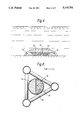
FIG. 8 is a plan view of a preferred form of the part shown in FIG. 7; and
FIG. 9 is a schematic cross section showing details of the preferred form of hollow tube of FIG. 8.
Referring now to FIG. 1(a), a suitable waste disposal vessel would, for example, be a sea going ship 1 of about 40,000 tonnes displacement. The ship has a dynamic positioning system using thrusters 2 to allow it to hold station over a selected seabed site during disposal operations. The ship also has sensors 3 (such as sonar transponders) mounted beneath the hull which allow monitoring of the seabed and monitoring of any objects beneath the ship. There is a hole or moon pool 4 formed through the hull of the ship and opening into the sea beneath the ship; this moon-pool 4 allows passage of a container or vehicle for waste material through the body of the ship and into the sea below.
As shown in FIG. 1(a) according to a first embodiment of the invention the ship has storage tanks 5 for carrying waste material. On the deck there is an A-frame gantry 6 which straddles the moon-pool. A container 7 is supported by a tether 8. The tether is a cable, chain or rope (e.g. "Kevlar" (trade mark)). If the tether is a cable, it may be wound on a reel (not shown). Preferably, the tether is a rope, and in this case the rope can be coiled in a rope store 9. The rope passes via a traction unit 10 to be attached to the container at an attachment swivel 11. The tether is sufficiently long to allow lowering of the container to the seabed; the container can be winched back to the ship from the seabed by means of the tether and the traction unit. The tether has a design strength sufficient to support the weight of a container and its contents (e.g. a breaking strain of several thousand tonnes) and should be designed to be capable of withstanding considerable stretching forces.
The container 7 shown in FIG. 2 has a casing of generally closed cylindrical shape and which defines a space for containing waste materials. The container is designed to be hung from the tether 8 by means of the attachment swivel 11. The base or bottom end of the container, opposite the swivel attachment, is closable by a door 12 mounted on a hinge 13. Seals 14 are provided between the casing ends and the door. A lock mechanism 15 is provided to releasably engage part of the door and there is a ram 16 connected to the lock mechanism to lock or unlock the sealing of the door. A second ram 17 is attached to the door in the vicinity of the hinge and is used to close the door.
A loading port 18 is provided in the upper part of the casing by means of which waste material may be loaded into the container. The loading port can be sealed after the container is loaded.
Also in the upper part of the container are mounted vent apertures fitted with non-return valves 19. The non-return valves provide passages for access into the interior of the container but prevent the exit of material from the container through the vents.
The container of this example is fabricated from steel, has a mass of about 120 tonnes and an internal capacity of about 2500 m3. This container could, for example, hold about 4000 tonnes of solid waste such as contaminated soil, dredged spoil, flyash and the like. Alternatively, the container could hold liquid wastes or slurries (e.g. sewerage sludge of about 5% solids by weight).
A method of waste disposal using the container will now be described by way of example, with reference to the use of a container of the type illustrated by FIG. 2.
Referring to FIG. 3, a general sequence of operation will be described. The ship is loaded with waste material and is taken to a deep water site suitable for waste disposal, FIG. 3(a). Waste material is then loaded into the container whilst the container is held within the moon-pool of the ship, FIG. 3 (b). The filled container is sealed and is then lowered towards the seabed on the tether. The ship is maintained in position by the dynamic positioning system. The position of the container relative to the ship and relative to the seabed is monitored during deployment of the container, FIG. 3(c).
As the container nears the seabed its descent is slowed so that the descent is arrested before it reaches the seabed. The container should stop about 10-50 m above the seabed.
The container carries a control pack (FIG. 2, numeral 20) which allows remote operation of the ram 16 to unlock the door of the container. As the door drops open under the weight of the contained waste, the waste material drops down to be deposited onto the seabed. The load on the tether is thereby reduced and any stretching of the tether will be reduced tending to allow the container to rise somewhat towards the surface. The tether is winched in to complete the retrieval of the container into the ships moon-pool, FIG. 3(d).
FIG. 4 shows in more detail some features of the sequence for waste disposal according to this embodiment of the invention. When the descent of the container is arrested just above the seabed, remote signalling can be used to check that the disposal system is ready for operation, FIG. 4(a). As shown in FIG. 4(b), as the door is released the contained material drops as a mass to the seabed under the influence of gravity. In order that the release of the waste material is not held back by the creation of a vacuum in the upper part of the container 21, the one way valves open as the waste drops. The cavity formed behind the waste material is flooded with sea water which replaces the expelled material.
As the sea water rushes into the container it tends to flush the waste material out through the open door, FIG. 4(c). As shown in FIG. 4(d), further flushing of the inside of the container occurs by the passage of seawater through the vents via the one way valves as the container is raised towards the surface with the door remaining open. Any traces of waste material will tend to be washed out of the container before the container gets near to the water surface.
By using this form of the invention it is possible to deposit a large mass of waster material directly onto the seabed at great depth without risk of polluting the sea water through which the material has had to pass on its journey from the surface to the seabed.
Various additional features may be included within the scope of this embodiment of the invention. For example, the inside surface of the container may be polished or treated with "non-stick" material in order to assist the smooth expulsion of the waste from the container at the seabed. Furthermore, the waste may have added to it various treating agents, e.g. chemical additives such as flocculants and/or stabilizers. The treating agents may be added to the waste material as it is loaded into the container, but alternatively there could be inlet ports in the casing of the container for introducing treating agents directly into the material. In some cases it is envisaged that the container will be filled to maximum capacity with waste material, and in other cases the container might be part-filled with sea water and the waste material then added thereto.
In describing a second embodiment of the invention, reference will be made to FIG. 5. Passing through a portion of the hull of the ship there is a moon-pool 4. In the moon-pool is mounted an elongate hollow tube 22 of circular cross section. On the deck of the ship, over the moon-pool, there is a gantry 23 housing a driving mechanism 24 which engages the periphery of the tube and can operate to control raising and lowering of the trunk relative to the hull of the ship. The driving mechanism in this embodiment comprises a set of toothed drive wheels 25 which engage notched portions 26 on the outer surface of the tube.
At the lower end of the tube there is an exit chute 27 in the form of an extension of the tube angled rearwardly relative to the ships hull. The chute is closable by a hinged door 28. When the tube is raised to its maximum extent a major portion of the tube projects above the deck of the ship, and the chute is received in a correspondingly shaped recess 29 in the underside of the hull.
The ship has sensors 3 (e.g., sonar transponders) to measure the water depth below the hull. The information received is used to ensure that when the tube is in a lowered position it does not ever actually touch the bottom. The ship has a dynamic positioning system in which satellite navigational aids are used to accurately locate the ship and thrusters 2 are used to maintain the ship's position over a selected subaqueous site.
The ship will travel to and from the selected site with the tube in the raised position and will lower the tube only at the site. When the tube is in the lowered position, waste material may be conveyed from the holds to the tube via conduits 30. In the illustrated embodiment there is a chemical treatment plant 31 on the deck through which waste material passes in the conduit between the hold and the tube. As shown, the tube holds a portion of waste material 60 above which there is a head of water 32. As an alternative the tube could contain waste material only. In any case, when the door of the exit chute is opened, as the ship moves slowly forward the waste material can pass out of the tube to be laid in a continuous strip on the seabed below the ship. Because the positioning system on the ship gives an accurate location for each strip of waste laid on the bottom, it is possible to repeat the process whereby successive strips are laid side by side or one on top of another to achieve subaqueous capping. Alternatively, a single ship may deposit both materials in a single traverse provided that it is suitably equipped, e.g. with two tubes instead of the single tube 22 shown in FIG. 5.
FIG. 6 shows how a capped site could be built up by first laying a surrounding wall 33 of clean waste, then laying successive strips of dirty waste 34, 35 within the wall, and finally covering over the dirty waste with a cap of clean waste 36. The site may be built up on a grid plan by criss-crossing the site with the ship. The disposal site could, for example, be a square with sides about 1 km in length. By using this technique there is an improvement in the chances that the waste material (especially contaminants from the dirty waste) will not be dispersed in the surrounding water.
Preferred features of this embodiment of the invention are shown in FIGS. 7, 8 and 9.
Referring to FIG. 7, the exit chute 27 is provided with a hydraulic ram 40 to control opening and closing of the door 12.
The tube is provided with one way valves 41 which will prevent escape of matter from inside the tube but which can allow the surrounding water to flow into the tube as waste flows out in order to maintain essentially constant the contained total volume inside the tube.
It is considered particularly desirable that waste material should be treated prior to laying at the subaqueous site. The presently preferred form of treatment is the incorporation of chemical reagents or additives to stabilise waste. Examples of such additives are flocculants and coagulants.
These additives may be mixed with the waste in a plant 31 on deck, but may be added by an injector 42, as shown in FIG. 7, as the waste enters the top of the tube. Additional injector nozzles 43 for applying chemical additives may be located at various parts of the tube and adjacent the exit chute.
In order to ensure thorough mixing of the waste with any additives an homogenising grating 44 may be placed across a lower part of the tube. It is expected that best results will be achieved in the use of the apparatus and method of this second embodiment of the invention if the waste which exits the chute is in the form of a cohesive coagulated paste like mass.
Another preferred form of this embodiment of the invention is shown in FIGS. 8 and 9. The hollow tube 22 is divided into the two sections down its length, one section containing clean waste 33 (for example, clean dredge spoil) and the other containing dirty waste 34 (for example, flocculated contaminated waste). The tube is housed in a triangular sectioned frame 50, which extends down the tube to the exit chute 27 (FIG. 9) where cameras 51 are mounted for monitoring the release of waste and the disposal site.
In the exit chute 27 the two sections of the tube are arranged so that the section containing the clean waste is disposed above the section containing the dirty waste. This ensures that as dirty waste is released from the tube clean waste is dumped on top of this dirty waste and it is thereby immediately capped.
It is to be understood this second embodiment of the invention may be put into practice either in a batch-mode or as a semi-continuous process. In the first case, as each batch of waste is loaded into the tube it is then laid onto the seabed. In the second case, waste is fed to the tube at a rate which substantially balances the rate at which waste is laid at the subaqueous site. An equilibrium is achieved whereby in operation the tube is kept part-filled. In this case, laying could be carried out continuously until such time as the supply of waste from the holds is exhausted.

Claims (22)

I claim:
1. A method of disposal of material on subaqueous ground substantially without said material coming into contact with the surrounding water, which comprises positioning a ship carrying said material above a selected site for disposal, transferring said material to a hollow tube which is divided longitudinally to provide separate channels for passage of a first waste material and of a second waste material to the subaqueous ground, conveying said material to a level at, or close to, said subaqueous ground and depositing said first material and said second material from said longitudinally divided hollow tube on to said subaqueous ground.
2. A method as claimed in claim 1, wherein said hollow tube is disposed within a frame.
3. A method as claimed in claim 2, wherein said frame is triangular in section.
4. A method as claimed in claim 1, wherein said tube has cameras mounted thereon for visual monitoring of the disposal method.
5. A method as claimed in claim 1, wherein said hollow tube is lowered to a level at, or close to, said subaqueous ground by drive means engaging the periphery of said tube.
6. A method of disposal of waste material on subaqueous ground substantially without said material coming into contact with the surrounding water, which comprises positioning and propelling a ship carrying said material to deposit a first relatively contaminated waste material at a level at, or close to, said subaqueous ground and to deposit a second relatively uncontaminated waste material over the deposited first material, said second material being deposited over said first material simultaneously with deposition of said first material, the step of depositing said material being accomplished using a bucket as a container or vehicle for depositing said material.
7. A method as claimed in claim 6, wherein said bucket is arranged to deposit said material through a hinged door at its base.
8. A method as claimed in claim 7, wherein said hinged door is opened and closed by hydraulic or pneumatic rams.
9. A method as claim 6, wherein said bucket is conveyed to said level by a rope, cable or chain.
10. A method as claimed in 6, wherein said bucket has its internal surface provided with a non-stick coating.
11. A method as claimed in claim 1, wherein said ship is held on station at said selected site by means of satellite navigational aids and thrusters.
12. A method as claimed in claim 1, wherein said ship is held on station at said selected site by means of sensors comprising sonar transponders.
13. A method as claimed in claim 1, wherein said material is subjected to processing prior to its transfer into a container or vehicle.
14. A method as claimed in claim 1, wherein said material is subjected to processing during the step of conveying said material to said level.
15. A method as claimed in claim 1, wherein said material is subjected to processing while it is in a container or vehicle before being conveyed to said level.
16. A method as claimed in claim 13, wherein said processing is a chemical treatment.
17. A method as claimed in claim 16, wherein said chemical treatment comprises flocculation and/or coagulation.
18. A method as claimed in claim 16, wherein chemical reagents or additives are injected into said material through one or more nozzles.
19. A method as claimed in claim 16, wherein chemical reagents or additives are mixed into said material by an homogenizing grating.
20. A method as claimed in claim 1, wherein said material is dredged spoils, contaminated soil, flyash, slurry or sewerage.
21. A ship adapted for disposal of material on subaqueous ground substantially without said material coming into contact with the surrounding water, which ship includes means for carrying said material, a container or vehicle adapted to transport said material to the subaqueous ground, and a moon-pool through which said container or vehicle is conveyed to said subaqueous ground;
said container or vehicle including vent apertures provided with non-return valves which, in use, permit water to enter the container or vehicle but prevent egress of said material therefrom; and
drive wheel means for engaging notched portions on the periphery of said container or vehicle.
22. A method of disposal of waste material on subaqueous ground substantially without said material coming into contact with the surrounding water, which comprises positioning and propelling a ship carrying said material to deposit a first relatively contaminated waste material at a level at, or close to, said subaqueous ground in strip-wise manner and to deposit a second relatively uncontaminated waste material over the deposited first material, said second material being deposited over said first material simultaneously with deposition of said first material.
US07/468,918 1989-01-23 1990-01-23 Apparatus and method for subaqueous waste disposal Expired - Lifetime US5115751A (en)

Priority Applications (1)

Application Number Priority Date Filing Date Title
US07/765,919 US5237946A (en) 1989-01-23 1991-09-24 Apparatus and method for transferring material to subaqueous levels

Applications Claiming Priority (4)

Application Number Priority Date Filing Date Title
GB898901420A GB8901420D0 (en) 1989-01-23 1989-01-23 Apparatus and method for deep sea waste disposal
GB898901421A GB8901421D0 (en) 1989-01-23 1989-01-23 Subaqueous capping for waste disposal
GB8901421 1989-01-23
GB8901420 1989-01-23

Related Child Applications (1)

Application Number Title Priority Date Filing Date
US07/765,919 Continuation-In-Part US5237946A (en) 1989-01-23 1991-09-24 Apparatus and method for transferring material to subaqueous levels

Publications (1)

Publication Number Publication Date
US5115751A true US5115751A (en) 1992-05-26

Family

ID=26294865

Family Applications (1)

Application Number Title Priority Date Filing Date
US07/468,918 Expired - Lifetime US5115751A (en) 1989-01-23 1990-01-23 Apparatus and method for subaqueous waste disposal

Country Status (3)

Country Link
US (1) US5115751A (en)
EP (1) EP0380301B1 (en)
DE (1) DE69004983T2 (en)

Cited By (11)

* Cited by examiner, † Cited by third party
Publication number Priority date Publication date Assignee Title
US5381751A (en) * 1993-11-17 1995-01-17 Oceaneering Technologies, Inc. Transportation and discharge of waste to abyssal depths
US5666394A (en) * 1996-04-23 1997-09-09 Northrop Grumman Corporation Thickness measurement gauge
US6343559B1 (en) * 1998-07-28 2002-02-05 Kress Corporation Transportation system for dredged material and method of levy building
US6497535B1 (en) 1998-07-28 2002-12-24 Kress Corporation Material distribution vessel and method for distributing material recovered in a dredging operation
US20050204589A1 (en) * 2000-02-24 2005-09-22 Thomas Dennis R Multi-purpose vessel and method for recovering, storing and/or offloading material in a dredging operation
US20050204588A1 (en) * 2000-02-24 2005-09-22 Platt Michael D Combined conveyor and operating boom apparatus and method
US7025553B1 (en) 1998-07-28 2006-04-11 Michael D. Platt Dredging vessel and method for recovering, transporting and off loading material
US20080273955A1 (en) * 2007-05-02 2008-11-06 International Truck Intellectual Property Company, Llc. Refuse collection device and disposal method for public transportation vehicles
US20090084735A1 (en) * 2005-01-26 2009-04-02 Taplin Steven B Sediment removal apparatus
DE102011102577B4 (en) * 2011-05-25 2012-09-13 Peter Kelemen Floating device and method for pushing an object into a water bottom
JP2018507107A (en) * 2015-11-03 2018-03-15 コリア インスティチュート オブ オーシャン サイエンス アンド テクノロジー Leachate discharge system and leachate discharge method for marine disposal sites

Families Citing this family (2)

* Cited by examiner, † Cited by third party
Publication number Priority date Publication date Assignee Title
GB9108922D0 (en) * 1991-04-25 1991-06-12 Copson Alex G Apparatus and method for transfering material to subaqueous levels
FR2712515A1 (en) * 1993-11-17 1995-05-24 Rougerie Francis Method of disposal of compacted domestic waste at sea

Citations (8)

* Cited by examiner, † Cited by third party
Publication number Priority date Publication date Assignee Title
JPS5369388A (en) * 1976-12-02 1978-06-20 Mitsubishi Heavy Ind Ltd Vessel for dropping stones
JPS56112386A (en) * 1980-02-13 1981-09-04 Mitsubishi Heavy Ind Ltd Floating weight screen barge
US4307679A (en) * 1979-12-21 1981-12-29 The United States Of America As Represented By The United States Department Of Energy Submergible barge retrievable storage and permanent disposal system for radioactive waste
US4400115A (en) * 1978-12-20 1983-08-23 Commissariat A L'energie Atomique Method for depositing material on the ocean bed and apparatus for performing the same
JPS59195487A (en) * 1983-04-22 1984-11-06 Mitsui Eng & Shipbuild Co Ltd Dump boat
JPS62198595A (en) * 1986-02-26 1987-09-02 Oomotogumi:Kk Method of spreading bulk into sea and working ship therefor
US4829923A (en) * 1986-01-06 1989-05-16 The Maersk Company Limited Sewage disposal
US4878446A (en) * 1986-11-11 1989-11-07 Nicolon B.V. Method for the forming and the deposition in a selected place of a bulk

Family Cites Families (6)

* Cited by examiner, † Cited by third party
Publication number Priority date Publication date Assignee Title
US3456824A (en) * 1967-02-20 1969-07-22 Richard H Smith Deep sea refuse disposal
US3595161A (en) * 1969-10-23 1971-07-27 Webbco Research & Dev Corp Method and apparatus for refuse disposal
NO140775C (en) * 1977-09-30 1979-11-07 Stolt Nielsens Rederi DEVICE FOR DOWNLOADING MASS FROM A SURFACE VESSEL TO A SITE ON THE SEAL
US4352590A (en) * 1979-06-11 1982-10-05 Parker William R Stabilization of erodible marine or fluviatile sediments
GB2179645A (en) * 1985-08-02 1987-03-11 Alexander George Copson Waste management system
GB2206543B (en) * 1987-06-25 1991-05-22 Maersk Co Ltd Waste disposal

Patent Citations (8)

* Cited by examiner, † Cited by third party
Publication number Priority date Publication date Assignee Title
JPS5369388A (en) * 1976-12-02 1978-06-20 Mitsubishi Heavy Ind Ltd Vessel for dropping stones
US4400115A (en) * 1978-12-20 1983-08-23 Commissariat A L'energie Atomique Method for depositing material on the ocean bed and apparatus for performing the same
US4307679A (en) * 1979-12-21 1981-12-29 The United States Of America As Represented By The United States Department Of Energy Submergible barge retrievable storage and permanent disposal system for radioactive waste
JPS56112386A (en) * 1980-02-13 1981-09-04 Mitsubishi Heavy Ind Ltd Floating weight screen barge
JPS59195487A (en) * 1983-04-22 1984-11-06 Mitsui Eng & Shipbuild Co Ltd Dump boat
US4829923A (en) * 1986-01-06 1989-05-16 The Maersk Company Limited Sewage disposal
JPS62198595A (en) * 1986-02-26 1987-09-02 Oomotogumi:Kk Method of spreading bulk into sea and working ship therefor
US4878446A (en) * 1986-11-11 1989-11-07 Nicolon B.V. Method for the forming and the deposition in a selected place of a bulk

Cited By (15)

* Cited by examiner, † Cited by third party
Publication number Priority date Publication date Assignee Title
US5381751A (en) * 1993-11-17 1995-01-17 Oceaneering Technologies, Inc. Transportation and discharge of waste to abyssal depths
US5666394A (en) * 1996-04-23 1997-09-09 Northrop Grumman Corporation Thickness measurement gauge
US7025553B1 (en) 1998-07-28 2006-04-11 Michael D. Platt Dredging vessel and method for recovering, transporting and off loading material
US6497535B1 (en) 1998-07-28 2002-12-24 Kress Corporation Material distribution vessel and method for distributing material recovered in a dredging operation
US6343559B1 (en) * 1998-07-28 2002-02-05 Kress Corporation Transportation system for dredged material and method of levy building
US20050204589A1 (en) * 2000-02-24 2005-09-22 Thomas Dennis R Multi-purpose vessel and method for recovering, storing and/or offloading material in a dredging operation
US20050204588A1 (en) * 2000-02-24 2005-09-22 Platt Michael D Combined conveyor and operating boom apparatus and method
US7326020B2 (en) 2000-02-24 2008-02-05 Mudhen, Llc Multi-purpose vessel and method for recovering, storing and/or offloading material in a dredging operation
US20090084735A1 (en) * 2005-01-26 2009-04-02 Taplin Steven B Sediment removal apparatus
US7526884B2 (en) 2005-01-26 2009-05-05 Steven B Taplin Sediment removal apparatus
US20090184059A1 (en) * 2005-01-26 2009-07-23 Taplin Steven B Sediment removal apparatus and method for removing sediment from open waterways
US7676966B2 (en) 2005-01-26 2010-03-16 Taplin Steven B Method for removing sediment from open waterways
US20080273955A1 (en) * 2007-05-02 2008-11-06 International Truck Intellectual Property Company, Llc. Refuse collection device and disposal method for public transportation vehicles
DE102011102577B4 (en) * 2011-05-25 2012-09-13 Peter Kelemen Floating device and method for pushing an object into a water bottom
JP2018507107A (en) * 2015-11-03 2018-03-15 コリア インスティチュート オブ オーシャン サイエンス アンド テクノロジー Leachate discharge system and leachate discharge method for marine disposal sites

Also Published As

Publication number Publication date
EP0380301A1 (en) 1990-08-01
DE69004983T2 (en) 1994-06-23
DE69004983D1 (en) 1994-01-20
EP0380301B1 (en) 1993-12-08

Similar Documents

Publication Publication Date Title
US5237946A (en) Apparatus and method for transferring material to subaqueous levels
US5115751A (en) Apparatus and method for subaqueous waste disposal
US4713896A (en) Inshore submersible amphibious machines
US11345450B1 (en) Method and apparatus for disposal of cuttings
US4150503A (en) Apparatus for excavation and earth removal from aquatic bottoms
JP4925950B2 (en) Dredging and landfill methods
US3456824A (en) Deep sea refuse disposal
CA2059375C (en) Apparatus and method for transferring material to subaqueous levels
US3590887A (en) Port facility ship sewage collection, transportation and disposal system
JPS584133B2 (en) dredging equipment
JP3008015U (en) Mud treatment equipment
JPH0960034A (en) Thin-layer dredging and discharging device
JP2868632B2 (en) Method and apparatus for dredging high organic sludge on water bottom surface
WO1987005878A1 (en) Inshore submersible amphibious machines
JPH07214027A (en) Treatment and treatment device of mud water
SU1758231A1 (en) Device for underwater mining of sapropels
JPS6073920A (en) Settled-mud dredger
JPS6073922A (en) Dredging method for settled mud
EP1603817B1 (en) Apparatus and method for transferring settled or suspended solids from an open vessel into a closed vessel
JPH1037229A (en) Dredge pollution control device
JP2628429B2 (en) Method for building landfills without polluting water with garbage and waste tires, equipment for loading garbage and system for building landfills
JPH0450233Y2 (en)
GB2228452A (en) Flexible barges and method of transporting cuttings
US3395663A (en) Deep sea refuse disposal
JPH08141536A (en) Mud treatment method and apparatus

Legal Events

Date Code Title Description
STCF Information on status: patent grant

Free format text: PATENTED CASE

AS Assignment

Owner name: DOI PATENT HOLDING CORPORATION

Free format text: ASSIGNMENT OF ASSIGNORS INTEREST.;ASSIGNOR:COPSON, ALEX G.;REEL/FRAME:006294/0308

Effective date: 19920929

FEPP Fee payment procedure

Free format text: PAYOR NUMBER ASSIGNED (ORIGINAL EVENT CODE: ASPN); ENTITY STATUS OF PATENT OWNER: SMALL ENTITY

FPAY Fee payment

Year of fee payment: 4

FPAY Fee payment

Year of fee payment: 8

REMI Maintenance fee reminder mailed
FPAY Fee payment

Year of fee payment: 12

SULP Surcharge for late payment

Year of fee payment: 11