US511358A - Telephone - Google Patents
Telephone Download PDFInfo
- Publication number
- US511358A US511358A US511358DA US511358A US 511358 A US511358 A US 511358A US 511358D A US511358D A US 511358DA US 511358 A US511358 A US 511358A
- Authority
- US
- United States
- Prior art keywords
- telephone
- diaphragm
- case
- magnet
- bearing
- Prior art date
- Legal status (The legal status is an assumption and is not a legal conclusion. Google has not performed a legal analysis and makes no representation as to the accuracy of the status listed.)
- Expired - Lifetime
Links
- OKTJSMMVPCPJKN-UHFFFAOYSA-N Carbon Chemical compound [C] OKTJSMMVPCPJKN-UHFFFAOYSA-N 0.000 description 10
- 229910052799 carbon Inorganic materials 0.000 description 10
- 230000006698 induction Effects 0.000 description 8
- 230000005540 biological transmission Effects 0.000 description 6
- XEEYBQQBJWHFJM-UHFFFAOYSA-N Iron Chemical compound [Fe] XEEYBQQBJWHFJM-UHFFFAOYSA-N 0.000 description 2
- 239000002023 wood Substances 0.000 description 2
- 229920000742 Cotton Polymers 0.000 description 1
- 230000002153 concerted effect Effects 0.000 description 1
- 239000004020 conductor Substances 0.000 description 1
- 238000010586 diagram Methods 0.000 description 1
- 229910052742 iron Inorganic materials 0.000 description 1
- 230000001105 regulatory effect Effects 0.000 description 1
- 239000000126 substance Substances 0.000 description 1
- 239000000725 suspension Substances 0.000 description 1
- 230000001755 vocal effect Effects 0.000 description 1
Images

Classifications
-
- H—ELECTRICITY
- H04—ELECTRIC COMMUNICATION TECHNIQUE
- H04M—TELEPHONIC COMMUNICATION
- H04M1/00—Substation equipment, e.g. for use by subscribers
- H04M1/02—Constructional features of telephone sets
- H04M1/03—Constructional features of telephone transmitters or receivers, e.g. telephone hand-sets
Definitions
- My invention relates to improvements in a combined microphone, electric-alarm and telvtop view of the frame.
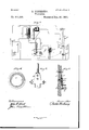
- FIG. 1 is a central longitudinal section and a part on line 1 1, Fig. 2, ot' the instrument with portions cut away.
- Fig. 2 is a top View or plan of the instrument with the front of the case removed.
- Fig. 3 is a section of the switches and the back of the case.
- Fig. 4. is a diaphragm and elastic ring.
- Fig. 5 is a diagram of the electric circuits.
- Fig. 6, is a Fig. '7 is a transverse section of the telephone case and contiguous parts, on line 7 Fig. 1.
- A is a quadrangular case with a projecting back, and A is the front of the case, which has an orifice serving as a mouth-piece, and an orifice for the adjusting screw.
- R is aV metallic frame, the front end supports the magnet and induction coil, H, the central portion of the helices U, and the rounded projection the bell N.
- This frame is securely fastened to the back of case by a screw.
- the permanent magnet 0, with parallel poles is bolted to the frame R, and to the outer pole is bolted the telephone case E, the top end of which is notchedgfor the reception of the spring contact 1", andthe armature lever v', and between which parts and the magnet, are small insulating substances, and between which said parts are securely held.
- the lower end of the case has a circular orilice for the reception of the plug 7, and like ledges are formed on the"face of saidplug and in the case, for a bearing for the vibrating plate 3; and from the recessot' the case is a small oritice opening through opposite of the mouth-piece.
- the case is held to the outer pole of the magnet by the bolts m, m.
- Both poles of the magnet are pierced directly Opposite, the outer to receive the threaded hollow electro-magnet 2, and the inner the electro-magnet 6.
- the former electro-magnet is surrounded by the helix 4, and the latter by the helix S.
- D is a bar held in notches of the sides of the case and against the back, and the left end has a button on which to hange a telephone, and the right end is connected to the switch F by a pin. Being moved by the switch a telephone can only be hung on the button of this bar, when the switch is in position for a call or signal.
- the switch J has a circular rim at its center, which has a bearing in the wood of the back. Within this rim is placed theinsulating button J', and over this is placed the switch F, and these several parts are held to the back by the bolt x.
- the switch J has contact with the metallic posts O4 and O5; and the switch F, has contacts with the posts O, O, O2, O3, O6 and O7. Both switches are provided with projections to handle them.
- the bolt m supports the adjusting spring l, which bears against the carbon button 5 and which bears against the diaphragm 3.
- To the xed end of the adjusting spring is attached one end of the primary coil of the induction helix H.
- S is the adjusting screw, by which the pressure of the carbon button on the diaphragm is regulated. It is held in the wood of case E and passes through an orifice of the magnet without contact therewith.
- L, L are binding screws for the line wires, B, B', for the local battery wires, and T,.T, for the telephone wires.
- the dotted lines Fig. 2 show the wire connections in the back, and the curved lines the visible'wire connections.
- Fig. 5 are shown diagrammatically the several electric circuits, B2 local battery and Ba battery at distant station, St.
- the microphonic circuit is thus, local battery B2, post O6, switch F, post O', telephone T2, helix 8- which may be omitted-helix 4:, diaphragm 3, carbon connection 5, adjusting spring 1, primary coil P, station battery B3 over line L2, back to local battery.
- Identical instruments must be used at both ends of the line.
- the terminals of the secondary coil of the induction helix I-I are connected to the line and to the primary coil.
- the telephone T2 may be left out of the circuit; then the electric circuit would, be from post O to helix 8, and then to helix 4; or direct from post O', to helix 4, as indicated by the curved dotted line.
- the helix 4, in its relation to the hollow electro-magnet 2 and the diaphragm 3, is made to vibrate in unison with a magnetic wave from a distant telephone, or the undulatory wave of a voltaic current from a distant microphone, and when the ear is placed against the mouthpiece of the instrument, the initial sounds are distinctly heard as they are transmitted.
- a circuit can be formed by a wire connecting the diaphragm with post O4 and over switch J, to post O5, thence to line wire L3.
- This electric circuit is identical in other respects with that heretofore described.
- the three parallel lines L3, are but one wire having distinct terminals.
- a spiral coil of bonnet wire 9-see Fig. Li-laid against the outer surface of the diaphragm forms an elastic bearing for said diaphragm, and the free end, extending beyond the bearing sur face, tends to arrest vibrations of said part.
- a small piece of carbon backed by a non-magnetic wire is best, andmay be insulated from the inclosing electro-magnet, but for the transmission of musical sounds the carbon should be dispensed with and a small wire substituted therefor, to produce the best results.
- the instrument When the instrument is operated in connection with batteries, the voltaic forces, are amplified by the magnetic wave of the telephone, and when the battery circuits are broken, the transmission is alone by the induced current of the electro-magnet or magnets, resulting from the vibrations of the diaphragm.
- the diaphragm and the carbon button form the electrodes where the variation of the circuit occurs, and one end of the primary coil of the induction helix may be attached to bolt m', or attached to the adjusting spring, which may be insulated from the magnet or not, as it is only requisite for the current to traverse the carbon.
- Fig. 4 is shown the diaphragm 3, on which is shown a spiral coil of bonnet wire 9,-that is, iron wire surrounded with cotton threadthe inner end of said coil extending beyond the case bearing, which is indicated by a circular dotted line.
- the outer part forms a flexible bearing for the plate or diaphragm, and the inner end tends to arrest the vibrations of said diaphragm.
- This flexible coil is preferably placed on the surface of the diaphragm next to the mouth-piece.
- the instrument When in use the instrument is attached to the wall of a room and the back A, is indispensable, but the instrument is operative without the inclosing part of the case and a suitable mouth-piece may be attached directly to the telephone case.
- a telephorjicinstrument comprising the permanent magnet C with the electro-magnet 2 and its helixe mounted in its pole, with the ICO tory action through air disturbances, and an adjustable contact with said plate producing partial disruptions with a charged electric circuit, and adapted to the transmission of messages by concerted action, substantially as described.
- the magneto-telephone comprising the case with orifice in the front surface, a bearing surface for the diaphragm, and a circular orifice through the back path, in combination with the plug, having a bearing surductors, substantially as described.
- the frame R provided with lugs for the support of the induction coil of the microphone, a lug for the support of the bell coils, ,post for the bellpand bearing for the support of the permanent magnet, substantially as described.
- the bonnet-Wire coil as a bearing for the under edge of said diaphragm, to give greater flexibility of movement, substantially as described.
- the frame R provided with lugs for the support of the induction coil of the microphone, a lug for the support of the bell coils, post for the bell and bearing for the support of the permanent magnet, substantially as set forth.
- the magneto-telephone comprising the case with orifice in the front surface, a bearing surface for the diaphragm and a circular orifice extending through the back in combination with the plug having a bearing surface and a central orifice, the magnet with an electro-magnet attached to its end, the induction coil and diaphragm, and means to unite said case and magnet to maintain the position of said plug against the edge of said diaphragm, and with suitable conductors, substantially as set forth.
- the bonnet wire coil as a bearing for the under edge of said diaphragm, to give greater exibility of movement, substantially as set forth.
Landscapes
- Engineering & Computer Science (AREA)
- Signal Processing (AREA)
- Electrostatic, Electromagnetic, Magneto- Strictive, And Variable-Resistance Transducers (AREA)
Description
(No Model.) v 2 Sheets-Sheet l.
B. PICKERING.
` TELEPHONE.
NO 511,358 Patented Dec. 26, 1893.
B. PIGKERING. TELEPHONE.
No. 511,358.. Patentearng. V26, 1893.
' w n N l N a T w n c.
' 1 NITED STATES- PATENT OFFICE.
BARTON PIOKERING, OF DAYTON, OHIO.
TELEPHONE.
SPECIFICATION forming part of Letters Patent No. 511,358, dated December 26, 1893.
Application filed January 29, 1881. Serial No. 24,990. (No model.) v
To @ZZ whom it may concern:
Be it known that I, BARTON PICKERING, a citizen of the United States, residing at Dayton, in the county of Montgomery and State of Ohio, have invented a certain new and useful Improvement in a Combined Microphone, Electric Alarm, and Telephone; and I do hereby declare that the following is a full, clear, and exact description of the invention, which will enable others skilled in the art to which it appertains to make and use the same, reference being had to the accompanying drawings, and to the letters and numerals of reference marked thereon, which form apart of this specincation.
My invention relates to improvements in a combined microphone, electric-alarm and telvtop view of the frame.
ephone.
The objects are to sound an alarm, to transmit and receive vocal messages or other sounds by voltaic and magnetic agencies. I attain these objects by the mechanism illustrated in the accompanying drawings, in which- Figure 1 is a central longitudinal section and a part on line 1 1, Fig. 2, ot' the instrument with portions cut away. Fig. 2, is a top View or plan of the instrument with the front of the case removed. Fig. 3, is a section of the switches and the back of the case. Fig. 4., is a diaphragm and elastic ring. Fig. 5, is a diagram of the electric circuits. Fig. 6, is a Fig. '7 is a transverse section of the telephone case and contiguous parts, on line 7 Fig. 1.
Similar letters and numerals designate like parts throughout the several views.
A, is a quadrangular case with a projecting back, and A is the front of the case, which has an orifice serving as a mouth-piece, and an orifice for the adjusting screw.
R is aV metallic frame, the front end supports the magnet and induction coil, H, the central portion of the helices U, and the rounded projection the bell N. This frame is securely fastened to the back of case by a screw.
The permanent magnet 0, with parallel poles is bolted to the frame R, and to the outer pole is bolted the telephone case E, the top end of which is notchedgfor the reception of the spring contact 1", andthe armature lever v', and between which parts and the magnet, are small insulating substances, and between which said parts are securely held. The lower end of the case has a circular orilice for the reception of the plug 7, and like ledges are formed on the"face of saidplug and in the case, for a bearing for the vibrating plate 3; and from the recessot' the case is a small oritice opening through opposite of the mouth-piece. The case is held to the outer pole of the magnet by the bolts m, m. Both poles of the magnet are pierced directly Opposite, the outer to receive the threaded hollow electro-magnet 2, and the inner the electro-magnet 6. The former electro-magnet is surrounded by the helix 4, and the latter by the helix S.
D is a bar held in notches of the sides of the case and against the back, and the left end has a button on which to hange a telephone, and the right end is connected to the switch F by a pin. Being moved by the switch a telephone can only be hung on the button of this bar, when the switch is in position for a call or signal.
The switch J, has a circular rim at its center, which has a bearing in the wood of the back. Within this rim is placed theinsulating button J', and over this is placed the switch F, and these several parts are held to the back by the bolt x. The switch J has contact with the metallic posts O4 and O5; and the switch F, has contacts with the posts O, O, O2, O3, O6 and O7. Both switches are provided with projections to handle them.
The bolt m, supports the adjusting spring l, which bears against the carbon button 5 and which bears against the diaphragm 3. To the xed end of the adjusting spring is attached one end of the primary coil of the induction helix H. S is the adjusting screw, by which the pressure of the carbon button on the diaphragm is regulated. It is held in the wood of case E and passes through an orifice of the magnet without contact therewith.
L, L are binding screws for the line wires, B, B', for the local battery wires, and T,.T, for the telephone wires. The dotted lines Fig. 2, show the wire connections in the back, and the curved lines the visible'wire connections.
IOO
At Fig. 5 are shown diagrammatically the several electric circuits, B2 local battery and Ba battery at distant station, St. The microphonic circuit is thus, local battery B2, post O6, switch F, post O', telephone T2, helix 8- which may be omitted-helix 4:, diaphragm 3, carbon connection 5, adjusting spring 1, primary coil P, station battery B3 over line L2, back to local battery. Identical instruments must be used at both ends of the line. The terminals of the secondary coil of the induction helix I-I, are connected to the line and to the primary coil.
The telephone T2, may be left out of the circuit; then the electric circuit would, be from post O to helix 8, and then to helix 4; or direct from post O', to helix 4, as indicated by the curved dotted line. The helix 4, in its relation to the hollow electro-magnet 2 and the diaphragm 3, is made to vibrate in unison with a magnetic wave from a distant telephone, or the undulatory wave of a voltaic current from a distant microphone, and when the ear is placed against the mouthpiece of the instrument, the initial sounds are distinctly heard as they are transmitted. Inasmuch as carbon is of low conductivity; a circuit can be formed by a wire connecting the diaphragm with post O4 and over switch J, to post O5, thence to line wire L3. This cuts out the microphone parts and leaves a metallic circuit, which is advantageous in transmitting over long lines, and is likewise advantageous in transmitting and receiving solely by the magneto-telephone of the instrument. This electric circuit is identical in other respects with that heretofore described. The three parallel lines L3, are but one wire having distinct terminals. A spiral coil of bonnet wire 9-see Fig. Li-laid against the outer surface of the diaphragm forms an elastic bearing for said diaphragm, and the free end, extending beyond the bearing sur face, tends to arrest vibrations of said part.
For transmission of speech a small piece of carbon backed by a non-magnetic wire is best, andmay be insulated from the inclosing electro-magnet, but for the transmission of musical sounds the carbon should be dispensed with and a small wire substituted therefor, to produce the best results. When the instrument is operated in connection with batteries, the voltaic forces, are amplified by the magnetic wave of the telephone, and when the battery circuits are broken, the transmission is alone by the induced current of the electro-magnet or magnets, resulting from the vibrations of the diaphragm.
The diaphragm and the carbon button form the electrodes where the variation of the circuit occurs, and one end of the primary coil of the induction helix may be attached to bolt m', or attached to the adjusting spring, which may be insulated from the magnet or not, as it is only requisite for the current to traverse the carbon.
On the frame R are mounted the helices U, and over the poles of which are held the armature lever fr, which carries the clapper c, and over said lever is the spring contact fr. When the voltaic current traverses the helices the armature is drawn down causing the clapper to strike the bell N; this movement breaks the circuit, and the clapper rebounds and renews the circuit, thereby producing a continuous vibratory movement of said clapper in contact with said bell. The ringing of this signal bell is caused by acurrent from a distant battery, and the ,electric circuit is as follows: battery B3, spring contact fr', armature lever fr, helices U, post O, switch F, post O3 to opposite pole of said battery. To ring a signal bell at a distant station, the electric circuitis as follows: local battery B2, post O7, switch F, post O2, line L3, signal bell, and line L2 to opposite pole of said battery.
At Fig. 4, is shown the diaphragm 3, on which is shown a spiral coil of bonnet wire 9,-that is, iron wire surrounded with cotton threadthe inner end of said coil extending beyond the case bearing, which is indicated by a circular dotted line. The outer part forms a flexible bearing for the plate or diaphragm, and the inner end tends to arrest the vibrations of said diaphragm. This flexible coil is preferably placed on the surface of the diaphragm next to the mouth-piece.
When in use the instrument is attached to the wall of a room and the back A, is indispensable, but the instrument is operative without the inclosing part of the case and a suitable mouth-piece may be attached directly to the telephone case.
Having thus fully described my invention, what I claim, and desire to secure by Letters Patent, is
l. The case E provided with a notch at its rear end, the permanent magnet C these supporting parts in combination with the binding bolt M, armature spring r with clapper attached, contact spring r', the latter two held in said notch, metallic frame R, helices U supported on said frame, and bell N held on a standard of said frame, anda charged electric circuit, substantially as and for the purpose specified.
2. The case E provided with an orifice, the plug 7 to till said orifice, in combination with the diaphragm 3 held on ledges of said case and plug, the permanent magnet C provided with the hollow electro-magnet 2, the carbon button 5, the adjusting spring l, the latter two having metallic connection and a charged electric circuit for microphonic transmission, substantially as described.
3. The case E with plug 7 in combination with the diaphragm 3, permanent magnet C with electro-magnets 2 and 6 mounted thereon, carbon button 5 with metallic stem, the adjusting spring l, the induction coil H, and a charged electric circuit for microphonic transmission, substantially as described.
4:. A telephorjicinstrument comprising the permanent magnet C with the electro-magnet 2 and its helixe mounted in its pole, with the ICO tory action through air disturbances, and an adjustable contact with said plate producing partial disruptions with a charged electric circuit, and adapted to the transmission of messages by concerted action, substantially as described.
6. The combination of the switch F, the pins or terminals O', O2, O3, O, O7, O6 for the several circuits the bar D attached at one end to said switch and button for the suspension of a telephone on the other, and the inclosing case A, substantially as described.
7. The magneto-telephone comprising the case with orifice in the front surface, a bearing surface for the diaphragm, and a circular orifice through the back path, in combination with the plug, having a bearing surductors, substantially as described.
8. In a combined telephone, microphone and alarm,the frame R provided with lugs for the support of the induction coil of the microphone, a lug for the support of the bell coils, ,post for the bellpand bearing for the support of the permanent magnet, substantially as described.
9. In a combined telephone and microphone having but a single vibrating diaphragm, the bonnet-Wire coil as a bearing for the under edge of said diaphragm, to give greater flexibility of movement, substantially as described.
l0. In a combined telephone, microphone and alarm the frame R provided with lugs for the support of the induction coil of the microphone, a lug for the support of the bell coils, post for the bell and bearing for the support of the permanent magnet, substantially as set forth.
ll. The magneto-telephone comprising the case with orifice in the front surface, a bearing surface for the diaphragm and a circular orifice extending through the back in combination with the plug having a bearing surface and a central orifice, the magnet with an electro-magnet attached to its end, the induction coil and diaphragm, and means to unite said case and magnet to maintain the position of said plug against the edge of said diaphragm, and with suitable conductors, substantially as set forth.
12. In acombined telephone and microphone having but a single vibrating diaphragm, the bonnet wire coil as a bearing for the under edge of said diaphragm, to give greater exibility of movement, substantially as set forth.
BARTON PICKERING.
Witnesses:
J. J. BELVILLE, CELIA L. CoonEY.
Publications (1)
| Publication Number | Publication Date |
|---|---|
| US511358A true US511358A (en) | 1893-12-26 |
Family
ID=2580181
Family Applications (1)
| Application Number | Title | Priority Date | Filing Date |
|---|---|---|---|
| US511358D Expired - Lifetime US511358A (en) | Telephone |
Country Status (1)
| Country | Link |
|---|---|
| US (1) | US511358A (en) |
-
0
- US US511358D patent/US511358A/en not_active Expired - Lifetime
Similar Documents
| Publication | Publication Date | Title |
|---|---|---|
| US511358A (en) | Telephone | |
| US692579A (en) | Electric gong. | |
| US4057688A (en) | Intercom embodying tap transducers | |
| US751829A (en) | billift | |
| US252641A (en) | Compound telephone | |
| US218873A (en) | Improvement in electric telephones | |
| US1228639A (en) | Sound-producing device. | |
| US2763719A (en) | Intercommunication devices | |
| US199041A (en) | Improvement in telephones | |
| US415990A (en) | Jacques paul zigang | |
| US231599A (en) | Telephone | |
| US544890A (en) | Max frank | |
| US1088771A (en) | Electromagnetic device. | |
| US482668A (en) | Electrical apparatus | |
| US334871A (en) | Telegraph-sounder | |
| US201488A (en) | Improvement in speaking-telephones | |
| US329982A (en) | Receiver for telephonic telegraphs | |
| US717407A (en) | Ear-massage apparatus. | |
| US1267060A (en) | Electric horn. | |
| US981864A (en) | Electric horn. | |
| US787936A (en) | Selective signaling device. | |
| US245600A (en) | Telephone-signal | |
| US1016202A (en) | Telephone and telegraph combination system. | |
| US217208A (en) | Improvement in electric telephones | |
| US436410A (en) | Electro-magnetic bell |