US511129A - donisthorpe - Google Patents
donisthorpe Download PDFInfo
- Publication number
- US511129A US511129A US511129DA US511129A US 511129 A US511129 A US 511129A US 511129D A US511129D A US 511129DA US 511129 A US511129 A US 511129A
- Authority
- US
- United States
- Prior art keywords
- fiber
- machine
- pawl
- gills
- teeth
- Prior art date
- Legal status (The legal status is an assumption and is not a legal conclusion. Google has not performed a legal analysis and makes no representation as to the accuracy of the status listed.)
- Expired - Lifetime
Links
- 239000000835 fiber Substances 0.000 description 21
- 210000002816 gill Anatomy 0.000 description 19
- 238000009987 spinning Methods 0.000 description 4
- 244000025254 Cannabis sativa Species 0.000 description 2
- 241000208202 Linaceae Species 0.000 description 2
- 235000004431 Linum usitatissimum Nutrition 0.000 description 2
- 240000008564 Boehmeria nivea Species 0.000 description 1
- 235000012766 Cannabis sativa ssp. sativa var. sativa Nutrition 0.000 description 1
- 235000012765 Cannabis sativa ssp. sativa var. spontanea Nutrition 0.000 description 1
- 102000029797 Prion Human genes 0.000 description 1
- 108091000054 Prion Proteins 0.000 description 1
- 230000009286 beneficial effect Effects 0.000 description 1
- 239000011230 binding agent Substances 0.000 description 1
- 235000009120 camo Nutrition 0.000 description 1
- 235000005607 chanvre indien Nutrition 0.000 description 1
- 239000003795 chemical substances by application Substances 0.000 description 1
- 210000001520 comb Anatomy 0.000 description 1
- 238000003306 harvesting Methods 0.000 description 1
- 239000011487 hemp Substances 0.000 description 1
- 230000000284 resting effect Effects 0.000 description 1
- 239000010902 straw Substances 0.000 description 1
Images

Classifications
-
- D—TEXTILES; PAPER
- D01—NATURAL OR MAN-MADE THREADS OR FIBRES; SPINNING
- D01G—PRELIMINARY TREATMENT OF FIBRES, e.g. FOR SPINNING
- D01G19/00—Combing machines
- D01G19/06—Details
- D01G19/08—Feeding apparatus
Definitions
- N ow our present invention consists in obtaining a softening and drawing or lashing andopening action-on the fiber while in or on the pins or gills-from the, feed end of the machine so that the opening and lashing strain is on the unweakened fiber and giving other advantages as will hereinafter be set forth-the fiber coming 0% such machine being advantageously taken off by any suitable taking off device or lapper arrangement.
- a suitable gill box machine (or set of gills or combs operating in a suitable framework or standard and driven or actuated as is well understood) we use one (or several) pair of feed and softening rollers at the feed end of the machine.
- one pair of such rollers onlyit being distinctly understood however that more than one pair may be used if desired.
- four pairs to be very advantageous for some purposes such as when treating china grass according to our present invention.
- the two rollers are advantageously fluted or corrugated, the flutes or corrugations intersecting with one another; but we do not limit our,- selves thereto.
- the top roller (which may or may not be driven) is pressed down on the lower one by its own weight or by springs or weights if desired.
- the other or lower roller is rotated forward a certain distance to feed forward the fiber on to the gills and then has a reverse motion given to it about half its forward motion-01 more or less.
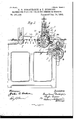
- Figure l is an end view (z'. e., the feed end) of agill box machine having our improvements applied thereto.
- Fig. 2 is a side elevation of Fig. 1part of each end of the machine being broken away.
- a is the top and b the lower of the pair of fluted feed rollers which are mounted in suitable lixed or stationary bearings and actuated as hereinafter described.
- 0 is the axis or shaft upon which the lower roller 1) isfirmly secured-and thereby revolved.
- d are the covers over the ordinary mechanism for actuating the gills of any suitable gill box e -as is well understood.
- f f are the drawing off rollers whichare driven so as to. drawoff the fiber from the gills of the gill box e. y
- a large drum may be used to lap the sliver as it comes through the rollers f or the fibenmay be drawn ofif'and delivered in any other suitable manner.
- h h are fast and loose pulleys which revolve the main driving shaft 2'.
- j is a toothed wheel which is actuated and slowly revolved (in the direction of the arrow m Fig. 2) by a suitable train of wheels geared down and driven from the main shaft 1'.
- k is a crank arm rigidly fixed to and revolved with j.
- n is a crank pin on a crank arm or lever 0 loosely pivoted so as to freely turn on the axle c of the roller 11.
- p is a toothed or ratchet wheel rigidly keyed or fixed on the axis a.
- s is a pawl on the lever arm 0.
- t is a pin or projection on the pawl s.
- 'u is a cam surface or fixed plate for the purpose of engaging the pin t and tripping the-pawl sout of the teeth'of the ratchetwheel p during part of the oscillating movement of 0.
- u isa spring which normally keeps thepawl t pressed into teeth 19 until disengaged therefrom by u.
- w is a second pawl hung loosely to armo andbygravityalways resting in the teeth of the wheel 19 which it forces around in the direction of arrow 2: and rides over said teeth. freely-when-arm 0 is movedin the opposite direction.
- y is a feeding apron of any suitable form
- rocking action is imparted to the rocking arm 0 (loosely pivoted on c) by means of the crank; it andcrank pin Z and connecting rodm and this loose arm 0, having the pawl w operating on one side thereof, thereby forces the wheelpround in the direction'of the arrow z -say eight teeth and thereby revolves the; "axis a and roller 1) (which axis 0 or roller 1) mayor may-not have a toothed wheel thereon meshing with a toothed wheel on the axis of the roller a'to identically revolve same-or a may simply revolve by friction.) While the loose arm 0 is thus moving in the direction of the arrowA (Fig.
- crank pin Z and connecting rod mnext move the loose arm 0 in the opposite direction to the arrow A and the pawl 20 then rides back loosely over the teeth of the wheel 1) while the pin tnow rides down the cam surfaceu until the arm 0 has been rocked (or moved) about half of its journey back whereupon the pawl s engages into the teeth of the I wheel 19 and revolves the latter back in the opposite direction to arrows z and so revolves teeth of the wheel 19 at an earlier or later moment according to whether a greater or less amount of backward motion respectively is required.
- the operation is as follows:-The fiber is fed between rollers a and b and pierced by the pins or gills of the gill box eand thereby dragged forwardas is Well known and understood. After the feed rollers have revolved forward a certain distance they are reversed (in the manner just'previously described) for about half the distance fed'forward and therebydrag back the fiber on the gills (i. e.,insthe opposite directionto that in which the gills are traveling and carrying the fiber) and thereby we obtain a veryeffeotiveand beneficial lashing and openingiand softening action on the fiber. The fiber is again fed forward between a and b fore-a given ,dis-
- the feed rollers may be :made to break, crush and soften the straw or woody part of flax or hemp or to softenchina grass or other fibers or separate and special-rollers for this purpose may :beadded if 'required. )Ve think it desirablehowever that a the fiber should be usually softened .and crushed or otherwise subjected to a preliminary treatment,decorticated or S0l1t0110d(0l1 a separate machine or machines) before :be-
- the fiber is suitably drawn od from the gills e byquickly revolving drawing 0E tendantwithout stopping the machine.
- crank 70 means for turning said gear 17 G'racechwchfltreet, London, Notarys wheel j; and the gill box 9 and drawing off Clerk;
Landscapes
- Engineering & Computer Science (AREA)
- Textile Engineering (AREA)
- Preliminary Treatment Of Fibers (AREA)
Description
(No Model.) 2 SheVetsSheet 1.
G. E. DONISTHORPE & T. BURROWS. MACHINE FOR PREPARING FIBERS FOR GOMBING 0R SPINNING.
No. 511,129. Patented Dec. 19, 1893.
(No Model.) 2 SheetsSheet 2. G. E. DONISTHORPE & T. BURROWS. MACHINE FOR PREPARING FIBERS FOR GOMBING OR SPINNING.
No. 511,129. Patented Dec. 19, 1893.
drawing off teeth of the gill box. In the old and uni- UNITED STATES PATENT Prion.
GEORGE E. DONISTHORPE AND TAYLOR BURROVVS, OF LONDON, ENGLAND.
MACHINE FOR PREPARING FIBERS FOR COMBING 0R SPINNING.
SPECIFIGATION forming part of Letters Patent No. 511,129, dated December 19, 1893. Application filed November 1, 1892. Serial No. 450,643. (No model.) Patented in England January 7, 1892, No. 371.
To all whom it may concern.-
Be it known that we, GEORGE EDMUND DONISTHORFE, merchant, of 12 Oat Lane, and TAYLOR BURROWS, engineer, of 88 Upper Kennington Lane, London, inthe county of Surrey, England, subjects of the Queen of Great Britain, have invented Improvements in Machines for Preparing Fibers for Gombing or Spinning, (for which we have obtained Lettofore usually efiected by means of the well' known gill box or gill head and then drawing off such fiber-after being so treatedby tearing it off 5. 8., drawing it from the end) through the pins, gills or versally used machines as is well known the drawing off strain is put upon the fiber as it comes off the gills, pins or teeth, that is after the fiber has been weakened by being pierced and opened by the pins of the gills; also the resulting sliver has been usually passed directly into a sliver can or vessel in which it is removed.
N ow our present invention consists in obtaining a softening and drawing or lashing andopening action-on the fiber while in or on the pins or gills-from the, feed end of the machine so that the opening and lashing strain is on the unweakened fiber and giving other advantages as will hereinafter be set forth-the fiber coming 0% such machine being advantageously taken off by any suitable taking off device or lapper arrangement.
With a suitable gill box machine (or set of gills or combs operating in a suitable framework or standard and driven or actuated as is well understood) we use one (or several) pair of feed and softening rollers at the feed end of the machine. For the sake of brevity and clearness we will describe one pair of such rollers onlyit being distinctly understood however that more than one pair may be used if desired. For instance we consider four pairs to be very advantageous for some purposes such as when treating china grass according to our present invention. I The two rollers are advantageously fluted or corrugated, the flutes or corrugations intersecting with one another; but we do not limit our,- selves thereto. The top roller (which may or may not be driven) is pressed down on the lower one by its own weight or by springs or weights if desired. The other or lower roller is rotated forward a certain distance to feed forward the fiber on to the gills and then has a reverse motion given to it about half its forward motion-01 more or less.
In order that our present invention may be easily understood and readily carried into practice we will proceed to fully describe the same with reference to the drawings hereunto.
annexed.
In the drawings, Figure l is an end view (z'. e., the feed end) of agill box machine having our improvements applied thereto. Fig. 2 is a side elevation of Fig. 1part of each end of the machine being broken away.
Forthe sake of example we have illustrated only one pair of feed rollers; but as before stated more than one pair of such rolls can be used if desired.
a is the top and b the lower of the pair of fluted feed rollers which are mounted in suitable lixed or stationary bearings and actuated as hereinafter described.
0 is the axis or shaft upon which the lower roller 1) isfirmly secured-and thereby revolved.
d are the covers over the ordinary mechanism for actuating the gills of any suitable gill box e -as is well understood.
f f are the drawing off rollers whichare driven so as to. drawoff the fiber from the gills of the gill box e. y
is a horizontal lapping apron or it may be vertical (or between the two points) or in place thereof a large drum may be used to lap the sliver as it comes through the rollers f or the fibenmay be drawn ofif'and delivered in any other suitable manner. 7
h h are fast and loose pulleys which revolve the main driving shaft 2'.
j is a toothed wheel which is actuated and slowly revolved (in the direction of the arrow m Fig. 2) by a suitable train of wheels geared down and driven from the main shaft 1'.
k is a crank arm rigidly fixed to and revolved with j.
l is a crank pin upon which is pivoted the connecting rod mwhich at its opposite end is pivoted on the pin a.
n is a crank pin on a crank arm or lever 0 loosely pivoted so as to freely turn on the axle c of the roller 11.
p is a toothed or ratchet wheel rigidly keyed or fixed on the axis a.
s is a pawl on the lever arm 0.
t is a pin or projection on the pawl s.
'u, is a cam surface or fixed plate for the purpose of engaging the pin t and tripping the-pawl sout of the teeth'of the ratchetwheel p during part of the oscillating movement of 0.
u isa spring which normally keeps thepawl t pressed into teeth 19 until disengaged therefrom by u.
w is a second pawl hung loosely to armo andbygravityalways resting in the teeth of the wheel 19 which it forces around in the direction of arrow 2: and rides over said teeth. freely-when-arm 0 is movedin the opposite direction.
y is a feeding apron of any suitable form;
rocking action is imparted to the rocking arm 0 (loosely pivoted on c) by means of the crank; it andcrank pin Z and connecting rodm and this loose arm 0, having the pawl w operating on one side thereof, thereby forces the wheelpround in the direction'of the arrow z -say eight teeth and thereby revolves the; "axis a and roller 1) (which axis 0 or roller 1) mayor may-not have a toothed wheel thereon meshing with a toothed wheel on the axis of the roller a'to identically revolve same-or a may simply revolve by friction.) While the loose arm 0 is thus moving in the direction of the arrowA (Fig. 2) the pawls rides loosely over the teeth of 19 until about halfway when the pin t of said pawl s strikes against the fixed plate to and rides up against same and thus lifts the pawl 8 out of the teeth 10 into about the position 3 shown in dotted lines in Fig. 2. The crank pin Z and connecting rod mnext move the loose arm 0 in the opposite direction to the arrow A and the pawl 20 then rides back loosely over the teeth of the wheel 1) while the pin tnow rides down the cam surfaceu until the arm 0 has been rocked (or moved) about half of its journey back whereupon the pawl s engages into the teeth of the I wheel 19 and revolves the latter back in the opposite direction to arrows z and so revolves teeth of the wheel 19 at an earlier or later moment according to whether a greater or less amount of backward motion respectively is required.
The operation is as follows:-The fiber is fed between rollers a and b and pierced by the pins or gills of the gill box eand thereby dragged forwardas is Well known and understood. After the feed rollers have revolved forward a certain distance they are reversed (in the manner just'previously described) for about half the distance fed'forward and therebydrag back the fiber on the gills (i. e.,insthe opposite directionto that in which the gills are traveling and carrying the fiber) and thereby we obtain a veryeffeotiveand beneficial lashing and openingiand softening action on the fiber. The fiber is again fed forward between a and b fore-a given ,dis-
tanceand again pulled back a :partzof (that is less than) the distance it was fed "forward,
and so on. The feed rollers may be :made to break, crush and soften the straw or woody part of flax or hemp or to softenchina grass or other fibers or separate and special-rollers for this purpose may :beadded if 'required. )Ve think it desirablehowever that a the fiber should be usually softened .and crushed or otherwise subjected to a preliminary treatment,decorticated or S0l1t0110d(0l1 a separate machine or machines) before :be-
ing fed to our hereinbefore described machine. The fiber is suitably drawn od from the gills e byquickly revolving drawing 0E tendantwithout stopping the machine.
With some fiberswhere only required for coarse yarns the fiberafter treatment-on this machine-willbe foundtobe-so farprepared that it may be taken direct from our said machine to the drawing and roving frames and thenspun-without any separate combing. Forstill more coarse work-such as binder twines for harvesting purposes "the fiber coming from our machine (particularly flax or hem'p)may be twisted up or-spun(after drawing) in-toacoarsetwine-orstrands for binding sheaves'or other purposes.
Having thus described our invention, what we claimas new, and desire to secure byzLetters Patentof the United States, is.-
In a machine for preparing fiber, the con1- bination with the feed roller a, of the feed roller lathe shaft-cprojecting -f-rom the end of said roller 1), thecog wheel pmounted upon said shaft 0, the oscillating lever 0 Eloosely pivoted on said shaft 0, and projecting up ward; the pawl w pivoted to said oscillating v V v l I lever and adapted to push said cog wheel forrollers f, substantially as and forthe purposes ward, the pawl s also pivoted to said lever, described.
andadapted to push said cog wheel baok- G. E. DONISTHORPE.
Ward; the pin t projecting from said pawl s; TAYLOR BURROWSL 5 the cam plate u adapted to engage said pint Witnesses:
and keep said pawl 8 clear of said cog wheel HENRY BIRKBEOK,
during part of the backward stroke of said 34SouthamptonBuiZdings,L0nd0n, England, lever, the connecting rod m, crank 70, and Chartered Patent Agent. gear wheel j mounted on the same shaft with THOMAS LAKE,
lo said crank 70; means for turning said gear 17 G'racechwchfltreet, London, Notarys wheel j; and the gill box 9 and drawing off Clerk;
Publications (1)
| Publication Number | Publication Date |
|---|---|
| US511129A true US511129A (en) | 1893-12-19 |
Family
ID=2579955
Family Applications (1)
| Application Number | Title | Priority Date | Filing Date |
|---|---|---|---|
| US511129D Expired - Lifetime US511129A (en) | donisthorpe |
Country Status (1)
| Country | Link |
|---|---|
| US (1) | US511129A (en) |
-
0
- US US511129D patent/US511129A/en not_active Expired - Lifetime
Similar Documents
| Publication | Publication Date | Title |
|---|---|---|
| US511129A (en) | donisthorpe | |
| US449477A (en) | hildreth | |
| US737268A (en) | Stop-motion for combing-machines. | |
| US392172A (en) | Evening mechanism for railway-heads | |
| US556872A (en) | Island | |
| US4706A (en) | Improvement in icardlng-engines | |
| US461171A (en) | Stopping mechanism for carding-machines | |
| US346396A (en) | briggs | |
| US421824A (en) | Btjry | |
| US1181678A (en) | Preparation of jute and other fibers for spinning. | |
| US631992A (en) | Apparatus for opening silk fibers. | |
| US400864A (en) | Stop-motion device for spinning and twisting machines | |
| US319989A (en) | Machines | |
| US399909A (en) | Balls of fiber oe sliver | |
| US390486A (en) | lawson | |
| US19531A (en) | Machinery for regulating the supply of reeving to spinning-machines | |
| US442586A (en) | Ley barraclough | |
| US469835A (en) | The hobhis peters co | |
| US289004A (en) | Richard kitson | |
| US221254A (en) | Improvement in machines for drawing wire | |
| US1874500A (en) | Stop motion for twister frames | |
| US209694A (en) | Improvement in stop-motions for spinning or twisting machines | |
| US1233988A (en) | Spinning-machine. | |
| US538537A (en) | Automatic stop mechanism for wool-combing machines | |
| US457354A (en) | Carding-machine |