US5110161A - Means of improving performance of swivelling pressure sealing devices - Google Patents
Means of improving performance of swivelling pressure sealing devices Download PDFInfo
- Publication number
- US5110161A US5110161A US07/612,258 US61225890A US5110161A US 5110161 A US5110161 A US 5110161A US 61225890 A US61225890 A US 61225890A US 5110161 A US5110161 A US 5110161A
- Authority
- US
- United States
- Prior art keywords
- nipple
- stem
- spacer
- axial bore
- housing
- Prior art date
- Legal status (The legal status is an assumption and is not a legal conclusion. Google has not performed a legal analysis and makes no representation as to the accuracy of the status listed.)
- Expired - Fee Related
Links
Images
Classifications
-
- F—MECHANICAL ENGINEERING; LIGHTING; HEATING; WEAPONS; BLASTING
- F16—ENGINEERING ELEMENTS AND UNITS; GENERAL MEASURES FOR PRODUCING AND MAINTAINING EFFECTIVE FUNCTIONING OF MACHINES OR INSTALLATIONS; THERMAL INSULATION IN GENERAL
- F16L—PIPES; JOINTS OR FITTINGS FOR PIPES; SUPPORTS FOR PIPES, CABLES OR PROTECTIVE TUBING; MEANS FOR THERMAL INSULATION IN GENERAL
- F16L37/00—Couplings of the quick-acting type
- F16L37/08—Couplings of the quick-acting type in which the connection between abutting or axially overlapping ends is maintained by locking members
- F16L37/084—Couplings of the quick-acting type in which the connection between abutting or axially overlapping ends is maintained by locking members combined with automatic locking
- F16L37/098—Couplings of the quick-acting type in which the connection between abutting or axially overlapping ends is maintained by locking members combined with automatic locking by means of flexible hooks
- F16L37/0985—Couplings of the quick-acting type in which the connection between abutting or axially overlapping ends is maintained by locking members combined with automatic locking by means of flexible hooks the flexible hook extending radially inwardly from an outer part and engaging a bead, recess or the like on an inner part
- F16L37/0987—Couplings of the quick-acting type in which the connection between abutting or axially overlapping ends is maintained by locking members combined with automatic locking by means of flexible hooks the flexible hook extending radially inwardly from an outer part and engaging a bead, recess or the like on an inner part the flexible hook being progressively compressed by axial tensile loads acting on the coupling
-
- F—MECHANICAL ENGINEERING; LIGHTING; HEATING; WEAPONS; BLASTING
- F16—ENGINEERING ELEMENTS AND UNITS; GENERAL MEASURES FOR PRODUCING AND MAINTAINING EFFECTIVE FUNCTIONING OF MACHINES OR INSTALLATIONS; THERMAL INSULATION IN GENERAL
- F16L—PIPES; JOINTS OR FITTINGS FOR PIPES; SUPPORTS FOR PIPES, CABLES OR PROTECTIVE TUBING; MEANS FOR THERMAL INSULATION IN GENERAL
- F16L27/00—Adjustable joints, Joints allowing movement
- F16L27/08—Adjustable joints, Joints allowing movement allowing adjustment or movement only about the axis of one pipe
- F16L27/0804—Adjustable joints, Joints allowing movement allowing adjustment or movement only about the axis of one pipe the fluid passing axially from one joint element to another
- F16L27/0808—Adjustable joints, Joints allowing movement allowing adjustment or movement only about the axis of one pipe the fluid passing axially from one joint element to another the joint elements extending coaxially for some distance from their point of separation
Definitions
- the present invention relates to fluid connectors and, more particularly, to swivelable fluid connectors.
- Two very important areas of concern related to pressure confining swivellable joints are the range of temperature over which the joint will safely operate and the corrosion that is experienced by the materials of the two main non-elastomer joint elements. It has been shown that by limiting the change in deformation an elastomer seal is subjected to during operation, the elastomer operational temperature range may be increased, particularly in the low temperature operation. This is very important because formulations of elastomers to achieve lowered temperature operation results in a loss of important mechanical/ physical properties such as abrasion resistance and tensile strength. The materials used to soften the elastomer to provide better "spring back" from low temperature deformation are lost over a period of time shortening seal life. To overcome shortened life, a more expensive elastomer having similar mechanical properties must be used.
- the present invention shows a very low cost means for achieving the minimal change in elastomer deformation in this class of devices.
- the means disclosed herein also provides the possibility of a second very important benefit which may be achieved by permitting the use of dissimilar materials for the two elements which swivel relative to each other.
- FIG. 1 illustrates an elevation view of a fitting assembly in accordance with the present invention.
- FIG. 2 is a section view taken along line 2--2 of FIG. 1.
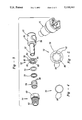
- FIG. 3 is an exploded perspective view of the fitting of FIG. 1.
- FIG. 4 is an end elevation view of a spacing element in accordance with the present invention.
- FIG. is an end elevation view of a spacing element in accordance with the present invention.
- FIG. 6 is a section view of a second embodiment in accordance with the present invention.
- FIG. 7 is an enlarged view of FIG. 6 within circle 7.
- FIG. 8 is an enlarged view like that of FIG. 7 of the sealing member without the housing stem.
- the swivellable fitting assembly 10 generally includes a housing 12, a rotatable nipple 14, and a conduit receiving housing 16.
- the conduit receiving housing 16 receives a conduit 18.
- the nipple 14 is coupled with a port 20 of a device 22 as seen in FIG. 1.
- the housing 12 generally has an overall cylindrical shape with a hollow body portion 30 with an extending stem 32.
- the stem 32 has an axial bore 34 therethrough opening into the interior 36 of the hollow body portion 30.
- the body portion 30 includes an opening 38 for receiving and retaining the conduit receiving housing 16.
- the housing 12 is formed from a metallic material such as steel and is stamped into a desired cylindrical configuration.
- the stem 32 includes a radially outward extending flange 40 which retains the nipple 14 axially about the stem 32.
- the nipple 14 is positioned onto the stem 32 prior to the stamping of the stem end which forms the flange 40 on the stem 32.
- the conduit receiving housing 16 generally includes a body 50 which is secured into the aperture 38 of body 30.
- the body 50 includes an axial bore 52 therethrough having bushing 54, sealing members 56, washer 57 and a conduit retainer 58.
- the particular conduit receiving housing 16 may vary depending upon the particular use of the fitting assembly.
- the nipple 14 has an overall cylindrical shape with a hex nut portion 60 and a cylindrical exterior threaded portion 62.
- the nipple 14 is rotatably positioned about the stem 32 to provide rotation of nipple 14 and housing 30 with respect to one another.
- the nipple 14 has an axial bore 64 having a diameter slightly larger than the outer diameter of stem 32 to enable the nipple 14 to be rotatably positioned over the stem 32.
- the bore 64 has increased diameter portions 66 and 68 to enable accommodation of sealing member 70 and spacer members 72, 74 and 76.
- the nipple 14 is generally manufactured from an aluminum material or the like providing a different type of material than the housing 12.
- the sealing member 70 is generally an elastomeric O-ring as illustrated in FIG. 6.
- Spacer 74 is an annular ring generally formed from a polymeric material, however, it could be formed of a metallic material.
- spacers 72 and 76 may also be formed from metallic or polymeric materials.
- Spacer 72 includes an annular flange 78 and a cylindrical corrugated sleeve portion 80.
- the corrugation portion 80 includes a plurality of raised plateaus 82 separated by a plurality of valleys 84. These plateaus 82 and valleys 84 have interior and exterior surfaces. The flat exterior surfaces of the plateaus 82 enable the spacer 72 to conform to the interior portion of the hex nut 60 to provide equal spacing within the hex nut portion 60.
- the spacer 72 abuts the inside of the hex portion 60 and positions and maintains the ring spacer 74 within the nipple 14. Also, the spacer 72 positions the sealing member 70 within the increased diameter bore 68. Spacers 72 and 74 prohibit off axis wobbling of the nipple 14 to maintain the sealing member 70 in a desired compressed state limiting compression of the sealing member, to provide optimum sealing between the stem 32 and the nipple 14.
- Spacer 76 has an overall cylindrical shape preferably of a polygonal design having a plurality of sides 88.
- the spacer 76 is positioned within increased diameter bore 66 surrounding the stem 32.
- the spacer 76 like spacers 74 and 72, prohibit off axis wobbling of the nipple 14 to maintain the optimum sealing of sealing member 70.
- the interior closed diameter portion of the spacer 76 is such that it is slightly larger than the diameter of the stem 32.
- the flange 78 of spacer 72 provides a bearing surface between the nipple 14 and the housing 30.
- the flange 78 is positioned such that during rotation of the nipple 14 or housing 12 that the movement has no adverse effect on the sealing of the seal member 70. Also, the flange 78 prohibits contact of the nipple 14 and housing 12 to reduce corrosion between the two.
- FIGS. 6-8 an alternate embodiment of the present invention is illustrated. Like elements will be designated with the same references numerals.
- the housing 12 is illustrated with stem 32 extending into nipple 14.
- Nipple 14 has a hex nut portion 60 and a cylindrical threaded exterior portion 62.
- the nipple 14 includes an axial bore 100 through the nipple 14.
- the axial bore 110 includes a pair of inwardly extending radial flanges 112 and 114 positioned within the axial bore 110. Also the axial bore 110 includes and increased diameter portion 116 positioned adjacent the nut portion 60. The flange 114 separates the increased diameter portion 116 from the axial bore 110 and the flange 112 is positioned adjacent the stem flange 40.
- the inward flanges 112 and 114 provide a spacing function for the nipple 14 with respect to the stem 32 as illustrated in FIG. 8.
- the sealing member 70 is substantially the same as that previously described.
- a bushing 120 having a flange 122 and a cylindrical portion 124 is positioned adjacent the sealing member to maintain the sealing member 70 within the nipple 14.
- the body 124 of the bushing 20 generally has an exterior surface adapted to contact the increased diameter portion of the fitting 14 and an interior surface 128 adapted to contact the stem 32 as illustrated in FIG. 6.
- the bushing 120 may include a right cylindrical body or a polygonal body to fit into the increased diameter bore 116 of the central bore 110.
- the bushing 120 acts like above described spacer 72.
- FIGS. 6-8 a very simple method of providing a swivelling nut that does not wobble on the stem of the swivelling body of the elbow is shown.
- the flanges 112 and 114 in the inside diameter of nut 14 are deformed as nut 14 is assembled over the stem portion 32 of swivel elbow housing 12.
- seal 70 seals between nut 14 and stem 32 and the rear closing and seal retaining bushing 120 assembles into bore 116 of nut 14.
- small flanges 112 and 114 are deformed to a point that allows accommodation of the manufacturing tolerances of nut 14 and stem portion 32.
- the flanges 112 and 114 may also deform stem portion 32.
Landscapes
- Engineering & Computer Science (AREA)
- General Engineering & Computer Science (AREA)
- Mechanical Engineering (AREA)
- Joints Allowing Movement (AREA)
- Joints With Pressure Members (AREA)
Abstract
Description
Claims (6)
Priority Applications (5)
Application Number | Priority Date | Filing Date | Title |
---|---|---|---|
US07/612,258 US5110161A (en) | 1990-11-13 | 1990-11-13 | Means of improving performance of swivelling pressure sealing devices |
PCT/US1991/008214 WO1992008920A1 (en) | 1990-11-13 | 1991-11-05 | Swivelling pressure sealing fluid connector |
AU90410/91A AU655616B2 (en) | 1990-11-13 | 1991-11-05 | Swivelling pressure sealing fluid connector |
EP92900312A EP0557414B1 (en) | 1990-11-13 | 1991-11-05 | Swivelling pressure sealing fluid connector |
JP4500930A JPH06502710A (en) | 1990-11-13 | 1991-11-05 | Rotary pressure seal fluid connector |
Applications Claiming Priority (1)
Application Number | Priority Date | Filing Date | Title |
---|---|---|---|
US07/612,258 US5110161A (en) | 1990-11-13 | 1990-11-13 | Means of improving performance of swivelling pressure sealing devices |
Publications (1)
Publication Number | Publication Date |
---|---|
US5110161A true US5110161A (en) | 1992-05-05 |
Family
ID=24452408
Family Applications (1)
Application Number | Title | Priority Date | Filing Date |
---|---|---|---|
US07/612,258 Expired - Fee Related US5110161A (en) | 1990-11-13 | 1990-11-13 | Means of improving performance of swivelling pressure sealing devices |
Country Status (5)
Country | Link |
---|---|
US (1) | US5110161A (en) |
EP (1) | EP0557414B1 (en) |
JP (1) | JPH06502710A (en) |
AU (1) | AU655616B2 (en) |
WO (1) | WO1992008920A1 (en) |
Cited By (14)
Publication number | Priority date | Publication date | Assignee | Title |
---|---|---|---|---|
WO1993020377A1 (en) * | 1992-03-31 | 1993-10-14 | Proprietary Technology, Inc. | Bead construction for fluid conduit |
US5395140A (en) * | 1993-05-13 | 1995-03-07 | Enhanced Applications, L.C. | Secondary latch and indicator for fluid coupling |
US5401063A (en) * | 1993-07-19 | 1995-03-28 | Enhanced Applications, L.C. | Primary/secondary retainer for beaded/flared tubing |
US5621959A (en) * | 1992-03-31 | 1997-04-22 | Proprietary Technology, Inc. | Method of attaching a bead assembly to a tubular conduit |
WO1998000663A1 (en) | 1996-07-02 | 1998-01-08 | Flex Technologies, Inc. | Connector assembly and method of manufacture |
EP0909916A3 (en) * | 1992-09-21 | 1999-11-17 | Proprietary Technology, Inc. | Means of coupling of non-threaded connections |
US20030094811A1 (en) * | 2001-11-20 | 2003-05-22 | Lutzke Matthew David | Secondary retention clip for fluid tube connection |
US20060188122A1 (en) * | 2004-01-29 | 2006-08-24 | Smith Richard C | Swivel elbow |
US20100083969A1 (en) * | 2005-06-16 | 2010-04-08 | Geoffrey Crumblin | Swivel elbow for mask assembly |
US8611969B2 (en) | 2004-01-29 | 2013-12-17 | Surefire, Llc | Cable assembly with earpiece |
US8625834B2 (en) | 2004-09-27 | 2014-01-07 | Surefire, Llc | Ergonomic earpiece and attachments |
US9157562B2 (en) | 2010-10-05 | 2015-10-13 | Baso Gas Products Llc | Positive swivel fitting |
USD839243S1 (en) | 2017-09-22 | 2019-01-29 | Surefire, Llc | Earpiece |
CN114688199A (en) * | 2022-04-22 | 2022-07-01 | 福建金汉科技有限公司 | Shock absorber joint with good sealing performance |
Families Citing this family (6)
Publication number | Priority date | Publication date | Assignee | Title |
---|---|---|---|---|
US5244185A (en) * | 1992-06-04 | 1993-09-14 | Ingersoll-Rand Company | Retainer |
US5775738A (en) * | 1992-09-21 | 1998-07-07 | Propiretary Technology, Inc. | Means of coupling of non-threaded connections |
WO1994007077A1 (en) * | 1992-09-21 | 1994-03-31 | Proprietary Technology, Inc. | Means of coupling of non-threaded connections |
US5655796A (en) * | 1992-09-21 | 1997-08-12 | Proprietary Technology, Inc. | Tubular assembly and method of making same |
JP2960964B2 (en) * | 1993-11-29 | 1999-10-12 | プロプライアタリー・テクノロジー・インコーポレーテッド | Conduit coupling |
US10047886B2 (en) | 2011-06-01 | 2018-08-14 | Elaflex Hiby Tanktechnik Gmbh & Co. | Breakaway coupling for a liquid line |
Citations (12)
Publication number | Priority date | Publication date | Assignee | Title |
---|---|---|---|---|
US398620A (en) * | 1889-02-26 | Leslie i | ||
US1436392A (en) * | 1922-11-21 | Swivel | ||
US1564934A (en) * | 1923-10-29 | 1925-12-08 | Vacher | Sprinkler |
US1657987A (en) * | 1923-08-20 | 1928-01-31 | John A Albertoni | Swinging joint |
US2560263A (en) * | 1946-05-09 | 1951-07-10 | Wright Aeronautical Corp | Fluid line connection |
CA485728A (en) * | 1952-08-12 | Resistoflex Corporation | Swivel coupling | |
USRE24786E (en) * | 1960-02-16 | Reusable hose end fitting for plural layer hose | ||
US3840264A (en) * | 1973-03-20 | 1974-10-08 | D Bennett | Swivel joint |
US3957205A (en) * | 1975-02-20 | 1976-05-18 | Costa Robert B | Sprinkler |
FR2417051A2 (en) * | 1978-02-09 | 1979-09-07 | Cabanot Jean Marie | Compression-type pipe coupling - has O=ring seal retaining collar screwed right inside nut into undercut region |
US4205866A (en) * | 1978-09-11 | 1980-06-03 | Aeroquip Corporation | Swivel joint |
US4456287A (en) * | 1982-01-15 | 1984-06-26 | Elkay Manufacturing Company | Rotary coupling |
-
1990
- 1990-11-13 US US07/612,258 patent/US5110161A/en not_active Expired - Fee Related
-
1991
- 1991-11-05 WO PCT/US1991/008214 patent/WO1992008920A1/en active IP Right Grant
- 1991-11-05 EP EP92900312A patent/EP0557414B1/en not_active Expired - Lifetime
- 1991-11-05 AU AU90410/91A patent/AU655616B2/en not_active Ceased
- 1991-11-05 JP JP4500930A patent/JPH06502710A/en not_active Withdrawn
Patent Citations (12)
Publication number | Priority date | Publication date | Assignee | Title |
---|---|---|---|---|
US398620A (en) * | 1889-02-26 | Leslie i | ||
US1436392A (en) * | 1922-11-21 | Swivel | ||
CA485728A (en) * | 1952-08-12 | Resistoflex Corporation | Swivel coupling | |
USRE24786E (en) * | 1960-02-16 | Reusable hose end fitting for plural layer hose | ||
US1657987A (en) * | 1923-08-20 | 1928-01-31 | John A Albertoni | Swinging joint |
US1564934A (en) * | 1923-10-29 | 1925-12-08 | Vacher | Sprinkler |
US2560263A (en) * | 1946-05-09 | 1951-07-10 | Wright Aeronautical Corp | Fluid line connection |
US3840264A (en) * | 1973-03-20 | 1974-10-08 | D Bennett | Swivel joint |
US3957205A (en) * | 1975-02-20 | 1976-05-18 | Costa Robert B | Sprinkler |
FR2417051A2 (en) * | 1978-02-09 | 1979-09-07 | Cabanot Jean Marie | Compression-type pipe coupling - has O=ring seal retaining collar screwed right inside nut into undercut region |
US4205866A (en) * | 1978-09-11 | 1980-06-03 | Aeroquip Corporation | Swivel joint |
US4456287A (en) * | 1982-01-15 | 1984-06-26 | Elkay Manufacturing Company | Rotary coupling |
Cited By (26)
Publication number | Priority date | Publication date | Assignee | Title |
---|---|---|---|---|
WO1993020377A1 (en) * | 1992-03-31 | 1993-10-14 | Proprietary Technology, Inc. | Bead construction for fluid conduit |
US5621959A (en) * | 1992-03-31 | 1997-04-22 | Proprietary Technology, Inc. | Method of attaching a bead assembly to a tubular conduit |
AU677569B2 (en) * | 1992-03-31 | 1997-05-01 | Proprietary Technology, Inc. | Bead construction for fluid conduit |
EP0909916A3 (en) * | 1992-09-21 | 1999-11-17 | Proprietary Technology, Inc. | Means of coupling of non-threaded connections |
US5395140A (en) * | 1993-05-13 | 1995-03-07 | Enhanced Applications, L.C. | Secondary latch and indicator for fluid coupling |
US5649724A (en) * | 1993-05-13 | 1997-07-22 | Enhanced Applications L.C. | Secondary latch and indicator for fluid coupling |
US5401063A (en) * | 1993-07-19 | 1995-03-28 | Enhanced Applications, L.C. | Primary/secondary retainer for beaded/flared tubing |
WO1998000663A1 (en) | 1996-07-02 | 1998-01-08 | Flex Technologies, Inc. | Connector assembly and method of manufacture |
US7618069B2 (en) | 2001-11-20 | 2009-11-17 | Cooper-Standard Automotive, Inc. | Secondary retention clip for fluid tube connection |
US20030094811A1 (en) * | 2001-11-20 | 2003-05-22 | Lutzke Matthew David | Secondary retention clip for fluid tube connection |
US20050062287A1 (en) * | 2001-11-20 | 2005-03-24 | Lutzke Matthew David | Secondary retention clip for fluid tube connection |
US6851725B2 (en) | 2001-11-20 | 2005-02-08 | Cooper Technology Services, Llc | Secondary retention clip for fluid tube connection |
US9479856B2 (en) | 2004-01-29 | 2016-10-25 | Surefire, Llc | Ergonomic earpiece |
US8611969B2 (en) | 2004-01-29 | 2013-12-17 | Surefire, Llc | Cable assembly with earpiece |
US9042947B2 (en) | 2004-01-29 | 2015-05-26 | Surefire, Llc | Multiple input acoustic coupler |
US20060188122A1 (en) * | 2004-01-29 | 2006-08-24 | Smith Richard C | Swivel elbow |
US10440459B2 (en) | 2004-01-29 | 2019-10-08 | Surefire, Llc | Ergonomic earpiece |
US8625834B2 (en) | 2004-09-27 | 2014-01-07 | Surefire, Llc | Ergonomic earpiece and attachments |
US10231048B2 (en) | 2004-09-27 | 2019-03-12 | Surefire, Llc | Ergonomic earpiece with attachment mount |
US9560436B2 (en) | 2004-09-27 | 2017-01-31 | Surefire, Llc | Ergonomic earpiece and attachments |
US10200778B2 (en) | 2004-09-27 | 2019-02-05 | Surefire, Llc | Earpiece with ergonomic extension |
US20100083969A1 (en) * | 2005-06-16 | 2010-04-08 | Geoffrey Crumblin | Swivel elbow for mask assembly |
US9878117B2 (en) * | 2005-06-16 | 2018-01-30 | Resmed Limited | Swivel elbow for mask assembly |
US9157562B2 (en) | 2010-10-05 | 2015-10-13 | Baso Gas Products Llc | Positive swivel fitting |
USD839243S1 (en) | 2017-09-22 | 2019-01-29 | Surefire, Llc | Earpiece |
CN114688199A (en) * | 2022-04-22 | 2022-07-01 | 福建金汉科技有限公司 | Shock absorber joint with good sealing performance |
Also Published As
Publication number | Publication date |
---|---|
AU655616B2 (en) | 1995-01-05 |
EP0557414A4 (en) | 1993-11-10 |
EP0557414A1 (en) | 1993-09-01 |
EP0557414B1 (en) | 1997-01-02 |
WO1992008920A1 (en) | 1992-05-29 |
JPH06502710A (en) | 1994-03-24 |
AU9041091A (en) | 1992-06-11 |
Similar Documents
Publication | Publication Date | Title |
---|---|---|
US5110161A (en) | Means of improving performance of swivelling pressure sealing devices | |
US4217923A (en) | Ball valve with readily removable ball and seats for high temperature environment | |
US6644430B2 (en) | Integral bushing assembly for a rack and pinion steering gear | |
JP3030289B2 (en) | Ball joint | |
US11209043B2 (en) | Socket assembly and method of making a socket assembly | |
US5799954A (en) | Coaxial sealing ring | |
EP3430279B1 (en) | Socket assembly and method of making a socket assembly | |
KR19990083642A (en) | Tubular Coupling | |
US20100025079A1 (en) | Electrical bonding device for telescoping fluid line assembly | |
EP3592999B1 (en) | Ball joint assembly | |
US4294428A (en) | Butterfly valve | |
US6685234B2 (en) | Fluid fitting with torque suppression arrangement | |
US20080145141A1 (en) | Joint and/or Bearing Arrangement | |
US3368852A (en) | Pin-type bushing assembly | |
JP2000142015A5 (en) | ||
CN211778499U (en) | Ball and socket assembly and solid axle assembly in a vehicle | |
US20080304902A1 (en) | Ball joint | |
JP4237624B2 (en) | Integrated bushing assembly for rack and pinion type steering system | |
US20030075876A1 (en) | Seal system | |
US4498679A (en) | Grease seal | |
GB2193296A (en) | Butterfly valve | |
JP2000193097A (en) | Sealing device | |
US20070034271A1 (en) | Residual pressure valve | |
EP1079165B1 (en) | Compression fitting | |
JPH0643335U (en) | Spherical sliding bush assembly |
Legal Events
Date | Code | Title | Description |
---|---|---|---|
AS | Assignment |
Owner name: PROPRIETARY TECHNOLOGY, INC., MICHIGAN Free format text: ASSIGNMENT OF ASSIGNORS INTEREST.;ASSIGNOR:BARTHOLOMEW, DONALD D.;REEL/FRAME:005508/0183 Effective date: 19901106 |
|
FEPP | Fee payment procedure |
Free format text: PAYOR NUMBER ASSIGNED (ORIGINAL EVENT CODE: ASPN); ENTITY STATUS OF PATENT OWNER: LARGE ENTITY |
|
FPAY | Fee payment |
Year of fee payment: 4 |
|
FEPP | Fee payment procedure |
Free format text: PAT HLDR NO LONGER CLAIMS SMALL ENT STAT AS SMALL BUSINESS (ORIGINAL EVENT CODE: LSM2); ENTITY STATUS OF PATENT OWNER: LARGE ENTITY |
|
FPAY | Fee payment |
Year of fee payment: 8 |
|
REMI | Maintenance fee reminder mailed | ||
LAPS | Lapse for failure to pay maintenance fees | ||
FP | Lapsed due to failure to pay maintenance fee |
Effective date: 20040505 |
|
STCH | Information on status: patent discontinuation |
Free format text: PATENT EXPIRED DUE TO NONPAYMENT OF MAINTENANCE FEES UNDER 37 CFR 1.362 |