US5108239A - Push-in fastener - Google Patents
Push-in fastener Download PDFInfo
- Publication number
- US5108239A US5108239A US07/710,889 US71088991A US5108239A US 5108239 A US5108239 A US 5108239A US 71088991 A US71088991 A US 71088991A US 5108239 A US5108239 A US 5108239A
- Authority
- US
- United States
- Prior art keywords
- legs
- leg
- fastener
- opening
- base portion
- Prior art date
- Legal status (The legal status is an assumption and is not a legal conclusion. Google has not performed a legal analysis and makes no representation as to the accuracy of the status listed.)
- Expired - Lifetime
Links
- 238000010276 construction Methods 0.000 claims description 2
- 238000000034 method Methods 0.000 claims description 2
- 238000003780 insertion Methods 0.000 claims 1
- 230000037431 insertion Effects 0.000 claims 1
- 229910000639 Spring steel Inorganic materials 0.000 description 1
- 239000012858 resilient material Substances 0.000 description 1
Images
Classifications
-
- F—MECHANICAL ENGINEERING; LIGHTING; HEATING; WEAPONS; BLASTING
- F16—ENGINEERING ELEMENTS AND UNITS; GENERAL MEASURES FOR PRODUCING AND MAINTAINING EFFECTIVE FUNCTIONING OF MACHINES OR INSTALLATIONS; THERMAL INSULATION IN GENERAL
- F16B—DEVICES FOR FASTENING OR SECURING CONSTRUCTIONAL ELEMENTS OR MACHINE PARTS TOGETHER, e.g. NAILS, BOLTS, CIRCLIPS, CLAMPS, CLIPS OR WEDGES; JOINTS OR JOINTING
- F16B37/00—Nuts or like thread-engaging members
- F16B37/02—Nuts or like thread-engaging members made of thin sheet material
Definitions
- This invention relates generally to a push-in type fastener having a pair of resilient legs adapted to contract towards each other when pressed into an opening in a workpiece and then expand when through the opening to lock the fastener to the workpiece and more particularly to such fastener having a tab lock to lock the legs together in proximity to their respective free-ends as a means of maintaining contact therebetween and preventing undesirable movement relative each other.
- Push-in fasteners have been known for many years. Examples of push-in fasteners where the legs are integral with each other can be seen in U.S. Pat. Nos. 2,369,962 and 2,471,247, the disclosures of which are incorporated herein by reference. Examples of push-in fasteners where the legs are not integral and yet engage each other adjacent their respective free-ends can be seen in U.S. Pat. Nos. 2,165,412; 2,275,119; 2,322,656; 2,330,770 and 2,369,962, the disclosures of which are incorporated herein by reference and which are of the type to which the present invention is addressed.
- the free-ends of such prior art fastener legs were either folded so as to nest together or were left spaced apart from each other leaving them susceptible to movement relative to each other.
- the present invention improves upon such fasteners by providing a tab lock on one leg adjacent its free-end to provide a pocket into which the free-end the other leg is received to lockingly connect the two legs together to restrain against undesirable movement of one leg relative the other and maintain contacting engagement therebetween.
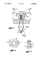
- FIG. 1 is a side elevation of a push-in Fastener 50 of the invention being used to secure a panel 10 to a workpiece 12;
- FIG. 2 is a top view of fastener 50 of FIG. 1 taken along view line 2--2';
- FIG. 3 is a view of tab 20 of leg 14' of fastener 50 of FIG. 1 taken along view line 3--3.
- Push-in fastener 50 of FIG. 1 is preferably a one piece construction folded into the configuration shown from a suitably resilient material such as a strip of suitable spring steel.
- Fastener 50 has a base portion 4 that is preferably flat and has a threaded aperture 11 (shown in FIG. 2) for receiving a threaded member such as screw 8 therethrough.
- FIG. 1 fastener 50 has been inserted through opening 16 in workpiece 12 and screw 8 has been used to threadingly secure panel 10 to fastener 50.
- Aperture 11 is surrounded by a frusto conical projection 6 having a warped helical edge 7 shown in FIG. 2 that is adapted to threadingly engage threads 13 of threaded fastener 8.
- a frusto conical projection 6 having a warped helical edge 7 shown in FIG. 2 that is adapted to threadingly engage threads 13 of threaded fastener 8.
- any form or type of threaded aperture through base portion 4 may be employed that is operative to receive a threaded member therethrough and become threadingly secured to it.
- Fastener 50 has a pair of resilient legs 14 and 14' that extend from base portion 4 on opposite sides of aperture 11. Legs 14 and 14' converge angularly towards each other to a location having a predetermined distance "L” from base portion 4. It is to be noted that distance “L” is the approximate distance by which panel 10 is held apart from workpiece 12 when secured thereto by fastener 50.
- Legs 14 an 14' then extend in substantial parallel relationship to each other in a direction substantially transverse to base portion 4 for a distance that is at least equivalent to finite thickness "T" of the wall of workpiece 12 surrounding opening 16.
- legs 14 and 14' then diverge angularly away from each other beneath opening 16, until a predetermined width "W 2 " therebetween is reached at which, in the compressed or contracted state when legs 14 and 14' are inserted and pressed downwardly into opening 16, width "W 2 " is sufficiently small to enable legs 14 and 14' to be received through opening 16 yet sufficiently large after having expanded away from each other upon emerging from the underside of opening 16 to effectively secure fastener 50 to workpiece 12.
- width "W 1 " of legs 14 and 14' within opening 16 is small enough such that legs 14 and 14' can be received into opening 16 when legs 14 and 14' are contracted together yet is large enough such that, when legs 14 and 14' expand in the region of "W 2 " after emerging from the bottom of opening 16, they engage the wall of workpiece 12 surrounding opening 16 to assist in securing fastener 50 to workpiece 12.
- legs 14 and 14' After having diverged away from each other to provide width "W 2 ", legs 14 and 14' then converge angularly towards each other in a direction away from base portion 4 and end in respective free-ends 18 and 18' with a section of leg 14' adjacent to free-end 18' folded about the surface of a section of leg 14 adjacent to free-end 18 that faces away from base portion 4 to provide a nested engagement therebetween.
- Leg 14' includes a tab 20 in proximity to free-end 18 that extends angularly away from leg 14' towards leg 14 in a direction away from base portion 4.
- Tab 20 is positioned such that free-end 18 of leg 14 is able to be received into the pocket between leg 14' and tab 20 to lockingly engage legs 14 and 14' together.
- the push-in fastener of the invention preferably further includes at least one lateral locking arm 21 that extends from at least one of legs 14 and 14' and bridges across the space therebetween and folds about the other leg to prevent shifting of one leg relative the other in a direction in and out of the page transversely to dimension "W 2 " as viewed in FIG. 1.
- the push-in fastener of the invention even more preferably includes a pair of opposed arms 21 and 21' that bridge across from one leg to the other leg from opposite edges of one leg or from an opposite edge of each leg so as to box legs 14 and 14' therebetween sufficiently to prevent shifting of one leg relative the other as the lateral direction.
- the arms need not extend about the leg whose lateral movement is being inhibited but need only engage an edge of the leg to effect the desired result.
- Locking arm such as arm 21 alone or arms 21 and 21' are positioned along legs 14 and 14' in proximity to the location above where tab 20 is located such that its length between legs 14 and 14' is less than "W 2 " so that it does not interfer with the process of pressing legs 14 and 14' into opening 16.
- arm 21 is preferably integral with one leg and folded about the other as shown in FIG. 1, it may also be in the form of a separate clip that folds about both legs to inhibit lateral movement.
- arm 21 need not be aligned parallel with base portion 4 and may be oriented angularly relative the leg from which it extends to facilitate folding as is well known to those skilled in the art.
- FIG. 3 shows a face view of tab 20 and FIG. 2 also shows where base portion 4 may include projections such as projections 9 and 9' on opposite sides of base portion 4 that extend in a direction substantially transverse to the direction of legs 14 and 14'.
- tab 20 maintains a locked engagement between free-ends 18 and 18' of legs 14 and 14' to insure integrity and prevent warpage and movement of legs 14 and 14' in proximity to respective free-ends 18 and 18' as legs 14 and 14' of fastener 50 are pressed into opening 16 to secure fastener 50 to workpiece.
Abstract
Description
Claims (5)
Priority Applications (1)
| Application Number | Priority Date | Filing Date | Title |
|---|---|---|---|
| US07/710,889 US5108239A (en) | 1991-06-06 | 1991-06-06 | Push-in fastener |
Applications Claiming Priority (1)
| Application Number | Priority Date | Filing Date | Title |
|---|---|---|---|
| US07/710,889 US5108239A (en) | 1991-06-06 | 1991-06-06 | Push-in fastener |
Publications (1)
| Publication Number | Publication Date |
|---|---|
| US5108239A true US5108239A (en) | 1992-04-28 |
Family
ID=24855947
Family Applications (1)
| Application Number | Title | Priority Date | Filing Date |
|---|---|---|---|
| US07/710,889 Expired - Lifetime US5108239A (en) | 1991-06-06 | 1991-06-06 | Push-in fastener |
Country Status (1)
| Country | Link |
|---|---|
| US (1) | US5108239A (en) |
Cited By (4)
| Publication number | Priority date | Publication date | Assignee | Title |
|---|---|---|---|---|
| US5322400A (en) * | 1993-03-03 | 1994-06-21 | Southco, Inc. | Nut plate fastener |
| US5774949A (en) * | 1997-08-27 | 1998-07-07 | Eaton Corporation | Trim clip |
| US5907126A (en) * | 1997-09-04 | 1999-05-25 | The Wiremold Company | Metal electrical outlet box with push-in screws for mounting electrical device |
| US20030185670A1 (en) * | 2000-11-16 | 2003-10-02 | Delta Electronics Inc. | Hot swap fan tray with fan guard |
Citations (16)
| Publication number | Priority date | Publication date | Assignee | Title |
|---|---|---|---|---|
| DE116844C (en) * | ||||
| US1702920A (en) * | 1921-08-25 | 1929-02-19 | John Edward Ogden | Expansion shield |
| US2165412A (en) * | 1936-03-21 | 1939-07-11 | George E Gagnier | Fastener |
| US2275119A (en) * | 1939-09-05 | 1942-03-03 | William R Wiley | Clip construction |
| US2313358A (en) * | 1941-12-31 | 1943-03-09 | Aircraft Tools Inc | Skin clamp |
| US2322656A (en) * | 1941-12-09 | 1943-06-22 | United Carr Fastener Corp | Snap fastener for trimming and like strips |
| US2330770A (en) * | 1939-09-05 | 1943-09-28 | William R Wiley | Clip construction |
| US2369962A (en) * | 1943-08-14 | 1945-02-20 | Gisondi Emanuel | Fastening device |
| US2471247A (en) * | 1948-08-25 | 1949-05-24 | Stadler John | Clip for attaching molding to automobile bodies and fenders |
| US2720135A (en) * | 1953-05-07 | 1955-10-11 | Gisondi Emanuel | Expanding screw anchor |
| FR1317534A (en) * | 1962-03-07 | 1963-02-08 | Flexible metal mounting clamp | |
| US3207022A (en) * | 1962-06-25 | 1965-09-21 | George A Tinnerman | Spring steel fasteners |
| US3523299A (en) * | 1965-09-20 | 1970-08-04 | George A Tinnerman | Thread engaging sheet metal fastener |
| FR2303983A1 (en) * | 1975-03-14 | 1976-10-08 | Raymond A Ste | Decorative trim retention clip for foam supports - has base to grip foam as spring clip is inserted |
| US4595325A (en) * | 1984-09-28 | 1986-06-17 | Eaton Corporation | Self-locking prevailing torque fastener |
| US4826375A (en) * | 1987-08-17 | 1989-05-02 | Eaton Corporation | Variable diameter screw fastener |
-
1991
- 1991-06-06 US US07/710,889 patent/US5108239A/en not_active Expired - Lifetime
Patent Citations (16)
| Publication number | Priority date | Publication date | Assignee | Title |
|---|---|---|---|---|
| DE116844C (en) * | ||||
| US1702920A (en) * | 1921-08-25 | 1929-02-19 | John Edward Ogden | Expansion shield |
| US2165412A (en) * | 1936-03-21 | 1939-07-11 | George E Gagnier | Fastener |
| US2275119A (en) * | 1939-09-05 | 1942-03-03 | William R Wiley | Clip construction |
| US2330770A (en) * | 1939-09-05 | 1943-09-28 | William R Wiley | Clip construction |
| US2322656A (en) * | 1941-12-09 | 1943-06-22 | United Carr Fastener Corp | Snap fastener for trimming and like strips |
| US2313358A (en) * | 1941-12-31 | 1943-03-09 | Aircraft Tools Inc | Skin clamp |
| US2369962A (en) * | 1943-08-14 | 1945-02-20 | Gisondi Emanuel | Fastening device |
| US2471247A (en) * | 1948-08-25 | 1949-05-24 | Stadler John | Clip for attaching molding to automobile bodies and fenders |
| US2720135A (en) * | 1953-05-07 | 1955-10-11 | Gisondi Emanuel | Expanding screw anchor |
| FR1317534A (en) * | 1962-03-07 | 1963-02-08 | Flexible metal mounting clamp | |
| US3207022A (en) * | 1962-06-25 | 1965-09-21 | George A Tinnerman | Spring steel fasteners |
| US3523299A (en) * | 1965-09-20 | 1970-08-04 | George A Tinnerman | Thread engaging sheet metal fastener |
| FR2303983A1 (en) * | 1975-03-14 | 1976-10-08 | Raymond A Ste | Decorative trim retention clip for foam supports - has base to grip foam as spring clip is inserted |
| US4595325A (en) * | 1984-09-28 | 1986-06-17 | Eaton Corporation | Self-locking prevailing torque fastener |
| US4826375A (en) * | 1987-08-17 | 1989-05-02 | Eaton Corporation | Variable diameter screw fastener |
Cited By (6)
| Publication number | Priority date | Publication date | Assignee | Title |
|---|---|---|---|---|
| US5322400A (en) * | 1993-03-03 | 1994-06-21 | Southco, Inc. | Nut plate fastener |
| GB2275750A (en) * | 1993-03-03 | 1994-09-07 | Southco | Sheet metal nuts |
| US5774949A (en) * | 1997-08-27 | 1998-07-07 | Eaton Corporation | Trim clip |
| US5907126A (en) * | 1997-09-04 | 1999-05-25 | The Wiremold Company | Metal electrical outlet box with push-in screws for mounting electrical device |
| US20030185670A1 (en) * | 2000-11-16 | 2003-10-02 | Delta Electronics Inc. | Hot swap fan tray with fan guard |
| US6749398B2 (en) * | 2000-11-16 | 2004-06-15 | Delta Electronics Inc. | Hot swap fan tray with fan guard |
Similar Documents
| Publication | Publication Date | Title |
|---|---|---|
| US2674149A (en) | Multiple pronged fastener device with spreading means | |
| US2720135A (en) | Expanding screw anchor | |
| US4641474A (en) | Sta-put wallboard joiner | |
| US2430555A (en) | Nut | |
| US2390750A (en) | Fastening device | |
| US2295685A (en) | Sheet metal nut or the like | |
| US2286042A (en) | Fastening device | |
| US3438664A (en) | Structural assembly and clip | |
| US4349106A (en) | Plastic ribbon for supply of bolt-like fastener elements | |
| US4580322A (en) | Quick release fastener | |
| US5108239A (en) | Push-in fastener | |
| US2400666A (en) | Fastening device | |
| US2283122A (en) | Nut device | |
| US2258845A (en) | Clip nut | |
| US10837481B2 (en) | Flush mount retainer assembly | |
| US2398827A (en) | Cowl fastener | |
| US2781073A (en) | Fastener and holder to engage a slotted panel | |
| US2070005A (en) | Spring nut | |
| US2367659A (en) | Nut | |
| US2387009A (en) | Rail fastening | |
| US2961723A (en) | Molding clip | |
| US2933007A (en) | Flat expanding insert having an arched connecting member | |
| US3193062A (en) | Self locking structure fastener | |
| US3059299A (en) | Door pan clip | |
| US2377694A (en) | Fastening device |
Legal Events
| Date | Code | Title | Description |
|---|---|---|---|
| AS | Assignment |
Owner name: EATON CORPORATION A CORP. OF OHIO, OHIO Free format text: ASSIGNMENT OF ASSIGNORS INTEREST.;ASSIGNOR:CLINCH, JAMES P.;REEL/FRAME:005735/0779 Effective date: 19910529 |
|
| FEPP | Fee payment procedure |
Free format text: PAYOR NUMBER ASSIGNED (ORIGINAL EVENT CODE: ASPN); ENTITY STATUS OF PATENT OWNER: LARGE ENTITY |
|
| STCF | Information on status: patent grant |
Free format text: PATENTED CASE |
|
| FPAY | Fee payment |
Year of fee payment: 4 |
|
| FPAY | Fee payment |
Year of fee payment: 8 |
|
| AS | Assignment |
Owner name: BANKBOSTON, N.A., AS AGENT, MASSACHUSETTS Free format text: AMENDED AND RESTATED PATENT COLLATERAL ASSIGNMENT AND SECURITY AGREEMENT;ASSIGNORS:TRANSTECHNOLOGY CORPORATION;SEEGER INC.;NORCO, INC.;AND OTHERS;REEL/FRAME:010628/0792 Effective date: 19990831 |
|
| AS | Assignment |
Owner name: TRANS TECHNOLOGY ENGINEERED COMPONENTS, LLC, OHIO Free format text: ASSIGNMENT OF ASSIGNORS INTEREST;ASSIGNOR:EATON CORPORATION;REEL/FRAME:012043/0530 Effective date: 19990831 |
|
| AS | Assignment |
Owner name: NATIONAL CITY BANK, AS AGENT, OHIO Free format text: ASSIGNMENT OF ASSIGNORS INTEREST;ASSIGNOR:TRANSTECHNOLOGY ENGINEERED COMPONENTS, LLC;REEL/FRAME:012707/0266 Effective date: 20011205 Owner name: TRANSTECHNOLOGY CORPORATION, NEW JERSEY Free format text: CORECTIVE ASSIGNMENT OT CORRECT COVERSHEET ID # 102011619.;ASSIGNOR:FLEET NATIONAL BANK (FORMERLY KNOWN AS BANKBOSTON, N.A.);REEL/FRAME:012946/0412 Effective date: 20011206 Owner name: SEEGER INC., NEW JERSEY Free format text: CORECTIVE ASSIGNMENT OT CORRECT COVERSHEET ID # 102011619.;ASSIGNOR:FLEET NATIONAL BANK (FORMERLY KNOWN AS BANKBOSTON, N.A.);REEL/FRAME:012946/0412 Effective date: 20011206 Owner name: TCR CORPORATION, MINNESOTA Free format text: CORECTIVE ASSIGNMENT OT CORRECT COVERSHEET ID # 102011619.;ASSIGNOR:FLEET NATIONAL BANK (FORMERLY KNOWN AS BANKBOSTON, N.A.);REEL/FRAME:012946/0412 Effective date: 20011206 Owner name: AEROSPACE RIVETS, CALIFORNIA Free format text: CORECTIVE ASSIGNMENT OT CORRECT COVERSHEET ID # 102011619.;ASSIGNOR:FLEET NATIONAL BANK (FORMERLY KNOWN AS BANKBOSTON, N.A.);REEL/FRAME:012946/0412 Effective date: 20011206 Owner name: NORCO, INC., CONNECTICUT Free format text: CORECTIVE ASSIGNMENT OT CORRECT COVERSHEET ID # 102011619.;ASSIGNOR:FLEET NATIONAL BANK (FORMERLY KNOWN AS BANKBOSTON, N.A.);REEL/FRAME:012946/0412 Effective date: 20011206 Owner name: TRANSTECHNOLOGY ENGINEERED COMPONENTS, OHIO Free format text: CORECTIVE ASSIGNMENT OT CORRECT COVERSHEET ID # 102011619.;ASSIGNOR:FLEET NATIONAL BANK (FORMERLY KNOWN AS BANKBOSTON, N.A.);REEL/FRAME:012946/0412 Effective date: 20011206 Owner name: TRANSTECHNOLOGY CANADA CORPORATION, CANADA Free format text: CORECTIVE ASSIGNMENT OT CORRECT COVERSHEET ID # 102011619.;ASSIGNOR:FLEET NATIONAL BANK (FORMERLY KNOWN AS BANKBOSTON, N.A.);REEL/FRAME:012946/0412 Effective date: 20011206 |
|
| REMI | Maintenance fee reminder mailed | ||
| FEPP | Fee payment procedure |
Free format text: PAYER NUMBER DE-ASSIGNED (ORIGINAL EVENT CODE: RMPN); ENTITY STATUS OF PATENT OWNER: LARGE ENTITY Free format text: PAYOR NUMBER ASSIGNED (ORIGINAL EVENT CODE: ASPN); ENTITY STATUS OF PATENT OWNER: LARGE ENTITY |
|
| AS | Assignment |
Owner name: TINNERMAN PALNUT ENGINEERED PRODUCTS, LLC, OHIO Free format text: RELEASE AND REASSIGNMENT;ASSIGNOR:NATIONAL CITY BANK, AS AGENT;REEL/FRAME:014964/0265 Effective date: 20040204 |
|
| AS | Assignment |
Owner name: ANTARES CAPITAL CORPORATION, AS AGENT, ILLINOIS Free format text: SECURITY AGREEMENT;ASSIGNOR:TINNERMAN PALNUT ENGINEERED PRODUCTS, LLC;REEL/FRAME:014990/0418 Effective date: 20040206 |
|
| FPAY | Fee payment |
Year of fee payment: 12 |
|
| SULP | Surcharge for late payment |
Year of fee payment: 11 |
|
| AS | Assignment |
Owner name: KTIN ACQUISITIONS, LLC, NEW YORK Free format text: MERGER;ASSIGNOR:TRANS TECHNOLOGY ENGINEERED COMPONENTS, LLC;REEL/FRAME:014499/0743 Effective date: 20011205 Owner name: TINNERMAN PALNUT ENGINEERED PRODUCTS, LLC., OHIO Free format text: CHANGE OF NAME;ASSIGNOR:KTIN, ACQUISTIONS, LLC;REEL/FRAME:014499/0747 Effective date: 20011205 Owner name: TRANS TECHNOLOGY ENGINEERED COMPONENTS, LLC, OHIO Free format text: ASSIGNMENT OF ASSIGNORS INTEREST;ASSIGNOR:NATIONAL CITY BANK;REEL/FRAME:014506/0130 Effective date: 20040407 |
|
| AS | Assignment |
Owner name: BNP PARIBAS, AS ADMINISTRATIVE AGENT UNDER CREDIT Free format text: ASSIGNMENT OF ASSIGNORS INTEREST;ASSIGNOR:TINNERMAN PALNUT ENGINEERED PRODUCTS, LLC;REEL/FRAME:015320/0321 Effective date: 20041101 Owner name: TINNERMAN PALNUT ENGINEERED PRODUCTS, LLC, OHIO Free format text: RELEASE OF SECURITY INTEREST;ASSIGNOR:ANTARES CAPITAL CORPORATION, AS AGENT;REEL/FRAME:015328/0066 Effective date: 20041029 |
|
| AS | Assignment |
Owner name: BNP PARIBAS, AS ADMINISTRATIVE AGENT UNDER TERM LO Free format text: ASSIGNMENT OF ASSIGNORS INTEREST;ASSIGNOR:TINNERMAN PALNUT ENGINEERED PRODUCTS, LLC;REEL/FRAME:015320/0951 Effective date: 20041101 |
|
| AS | Assignment |
Owner name: TINNERMAN PALNUT ENGINEERED PRODUCTS, INC., OHIO Free format text: CHANGE OF NAME;ASSIGNOR:TINNERMAN PALNUT ENGINEERED PRODUCTS, LLC;REEL/FRAME:022552/0270 Effective date: 20041101 |
|
| AS | Assignment |
Owner name: TINNERMAN PALNUT ENGINEERED PRODUCTS, INC., OHIO Free format text: RELEASE BY SECURED PARTY;ASSIGNOR:BNP PARIBAS;REEL/FRAME:023438/0013 Effective date: 20091028 |
|
| AS | Assignment |
Owner name: A. RAYMOND ET CIE, FRANCE Free format text: ASSIGNMENT OF ASSIGNORS INTEREST;ASSIGNORS:TINNERMAN PALNUT ENGINEERED PRODUCTS, INC.;TINNERMAN PALNUT, INC.;REEL/FRAME:023486/0629 Effective date: 20091028 |