US510388A - Thomas lanigan - Google Patents
Thomas lanigan Download PDFInfo
- Publication number
- US510388A US510388A US510388DA US510388A US 510388 A US510388 A US 510388A US 510388D A US510388D A US 510388DA US 510388 A US510388 A US 510388A
- Authority
- US
- United States
- Prior art keywords
- belt
- bale
- bight
- loop
- press
- Prior art date
- Legal status (The legal status is an assumption and is not a legal conclusion. Google has not performed a legal analysis and makes no representation as to the accuracy of the status listed.)
- Expired - Lifetime
Links
Images


Classifications
-
- B—PERFORMING OPERATIONS; TRANSPORTING
- B30—PRESSES
- B30B—PRESSES IN GENERAL
- B30B9/00—Presses specially adapted for particular purposes
- B30B9/30—Presses specially adapted for particular purposes for baling; Compression boxes therefor
- B30B9/3003—Details
- B30B9/301—Feed means
-
- A—HUMAN NECESSITIES
- A01—AGRICULTURE; FORESTRY; ANIMAL HUSBANDRY; HUNTING; TRAPPING; FISHING
- A01F—PROCESSING OF HARVESTED PRODUCE; HAY OR STRAW PRESSES; DEVICES FOR STORING AGRICULTURAL OR HORTICULTURAL PRODUCE
- A01F15/00—Baling presses for straw, hay or the like
- A01F15/07—Rotobalers, i.e. machines for forming cylindrical bales by winding and pressing
-
- A—HUMAN NECESSITIES
- A01—AGRICULTURE; FORESTRY; ANIMAL HUSBANDRY; HUNTING; TRAPPING; FISHING
- A01F—PROCESSING OF HARVESTED PRODUCE; HAY OR STRAW PRESSES; DEVICES FOR STORING AGRICULTURAL OR HORTICULTURAL PRODUCE
- A01F15/00—Baling presses for straw, hay or the like
- A01F15/07—Rotobalers, i.e. machines for forming cylindrical bales by winding and pressing
- A01F2015/0795—Pressing chamber with variable volume
Definitions
- My invention relates, generally, to balingpresses for cotton and other fibrous materials and, particularly, to certain improvements in that class thereof in which thefibers are compressed into cylindrical bales.
- My invention consists, first, in improved mechanism for baling cotton and other fibrous materials, which consists in feeding and simultaneously subjecting the same, in the form of a hat or sheet, to friction and pressure during the baling operation, by means of a belt, within the loop or bight of which the bale is formed by continuous accretion and rotation of the fiber, and byeffecting its compression in detail, or layer upon layer, as it is fed to the halo, which is preferably efiected, when baling cotton, by delivering the sheet or bat into-the press from the condenser of a gin in an unbroken condition; second, in mechanism for causing the hat or sheet of fiber, as it is fed into the press, to
- the objects of myinvention'are first, to so press the bat, as it is delivered from thecotton-gin condenser or elsewhere,that its fibers will not be broken or subjected to any deteriorating in fiuence, and, also, to avoid the danger that is inseparable from the use of a lint room; second, to effect such condensation of the fiber,in the first instance, as will place it in proper condition for ocean and other shipment, and thus obviate the present enormous expense of hauling it to storage warehouses and compresses and, also, of recompressing plantation bales; third, to efiect the compression or baling of the fiber by winding thebat smoothly, or without taugling or twistingits fiberaround a small, removable spindle, so thatthe pressure upon the fiber will constitute the main retaining element or holding means for the completed bale, and so that any light wrapping or covering which will arrest the expansion of the outer layer of the bat, will also prevent all expansion of the rest of said halo, and, also
- the numeral 1 indicates the endless, retaining and compression belt, which passes over the roller 2, around the bale 3, around the roller 4, over the suspension roller 5 and the guide roller 6, around or under the heavy tension-roller 7, and thence upward to the starting point
- This arrangement of the endless belt forms the loop or bight which receives the fibrous material as it passes between the rollers 2 and 4 and is undergoing the method of baling.
- the rollers 4, 5 and 6 rotate in ordinary, fixed journal-boxes, not shown, while the roller 2 is journaled at the upper end of the sliding frame 8, which is raised and lowered by the screw-and-bevelwvheel gearing 9, as shown in ing the friction upon said bale.
- the heavy tension-roller 7 is supported by the belt 1, except when at its extreme lower position, when its journals rest in the bottoms of the guide grooves 10; also, this idler is raised and lowered by the belt 1, being guided by its journals in said grooves. If desired, however, sliding journal boxes may be employed for the journals of this roller.
- the endless belt 1 is driven by frictional contact with the rollers 1 and 5, on the ends of which, as shown in Fig. 2, are secured the gear-wheels 1 and 5', which mesh with the smaller gear-wheel 5", so that they may be revolved in the same direction. Power for driving these gear-wheels and rollers may be transmitted from the condenser or other suitable source.
- Fig. 1 of the drawings only so much of the condenser 11 is represented as is necessary to show its connection with the baliugpress by the conveying apron 12, which receives the bat 13 from said condenser and conveys it to said press.
- This apron passes over and is rotated by the rollers 14, and 15, which are to be driven at the same speed.
- the operation will be as fo1lows:--The bat 13 is first started through the opening between the rollers 2 and at and then turned or wound over and over upon itself, in layers, and around a smallangular spindle, 16, until it assumes the form of a small roll, which, at first, is as light and decay as the bat of which it is formed, but which gradually becomes denser, as material is added and the friction increased, until it distends the loop or bight of the belt 1 into circular form and gradually lifts the heavy tension-roller 7, which, being continued, results in the formation of the desired size of bale within said loop or bight of the belt.
- the removable shaft or spindle 16 and mount the same in movable journal-boxes, 17, which slide upon the guides or ways 18, as shown in end and plan views, respectively, in Figs. 1, 2
- the removable part of this spindle is formed with angular ends, 19, which fit into correspondingly-shaped recesses in its adjacent parts, which, on being disconnected, permit of the removal of ,said spindle and the bale wound thereon; also, for the same purpose, said spindle may extend through the bale andrest; at its ends in journal-boxes having removable tops, or it may consist of one or two short, angular, removable journals projecting into and driving an angularly-hollowed spindle or shaft-within the bale, it being only necessary to provide some suitable means for the ready removal of said spindle after the completion of the bale..
- rollers 14 and 15 operate the conveying or feeding apron at a uniform rate of speed and, consequently, deliver the sheet or bat 13 inuniform quantity into the loop or bight of the belt 1, it follows, as the diameter of the bale 3 gradually increases from the start, oras each" layer of fiber is added thereto, that provision must be made for gradually lessening the rate of rotation of said bale as it increases in diameter, so as to prevent the rupture of said bat and consequent discontinuation of its delivery to the press.
- a differential or variable-speed gear illustrated in Fig.4 of the drawings, in which the shaft 16 is provided with a large metallic disk, 20, which is gripped between the two smaller friction-wheels 21, which are secured to the inner ends of the horizontally-arranged shafts 22 and driven in reverse or opposite directions over the faces of said disk by suitable gearing, 23, connected to the outer ends of said shafts.
- a bifurcated spring, 24, which is suitably secured at its outer end and projects inwardly to a point near said friction-wheels, where its arms or branches, 25, are pivoted to collars,26,surroundingsaidshafts.
- baling cotton and other loose fibrous materials are also incident to the modified construction of baling-press illustrated in Figs.
- This wheel has variable speed imparted thereto by the bevel-gear wheel 35, the power-pulley 36, the intermediate, reversely-arranged, conical pulleys 37, the endless-belt 38, connecting the same, and the pivoted lever 39, which is provided at its outer end with the fork 40 for r 5 shifting the belt upon said conical pulleys.
- this pivoted lever is provided with the friction disk 4], which, normally, or when the press is empty and in condition for starting, rests against the outer surface of the belt 1 at a. point just beneath the spindle 16.
- the friction disk 4 As the sheet or bat of fiber is delivered upon said belt and turned or wound around said spindle, layer upon layer, and as the diameter of the bale being formed gradually increases from the start, the loop or bight of the belt becomesenlarged, presses downward the friction-disk 41 on the inner end of the pivoted lever 39 and raises the outer forked end thereof, which shifts or raises the endless belt 38 over the peripheries of the conical pulleys 37.
- baling-press in baliug cotton. and other fibrous materials is the same as that incident to the 5 press illustrated in Figs. 1 and 4, which is that a, uniform peripheral speed is imparted to the bale from the commencement of its formation, an unbroken or continuous feed of the sheet or hat of fiber is secured, and a 40 bale is formed in which. each. layer, com menoing with the center one, is simultaneously subjected to compression upon both sides and to the friction of the belt upon its-outer side; also, each outer layer is more tightly wound 5 and compressed by the constant contraction of the next inner layer, which is drawn inward toward the center of the bale or spindle and subjected to the further friction and pressure transmitted through said outer layer. After the bale has been completed, it is wrappedmovered or bound and removed, from the press in the same manner as. above explained.
- balin g press 5 for cotton and other fibrous materials, its advantages, and the construction, arrangement, or combination of its several parts, what I claim. as new is 1.
- a baling-press for cotton and other loose fibrous materials,thecombination with feeding mechanism and a belt arranged to form an expansible loop or bight, of. means for subjecting said materials to simultaneous friction and pressure within said loop or bight, substantially as described.
- a baling-press for cotton and other loose fibrous materials the combination, with feeding mechanism and a belt arranged to form an expansible loop or bight, of means for winding said material from the center of the bale, layer upon layer, and for simultaneously subjecting the same to friction and pressure, substantially as described.
- a baling-press for cotton and other loose fibrous materials the combination, with feeding mechanism and a belt arranged to form an expansible loop or bight, of means for subjecting said materials to simultaneous friction and pressure within said loop or bight, said means consisting of a weight at tached to said belt, and a revolving spindle arranged within said loop or bight,,substan tially as described.
- a baling-press for cotton and other loose fibrous materials the combination, with feeding mechanism and a belt arranged to form an expansibl e loop or bight, of a weight connecting-with said belt, a spindle arranged within said loop or bight and means for imparting variable speed to said spindle, substantially as described.
- a baling-press for cotton and other loose fibrous materials the combination, with feeding mechanism, an endless, traveling belt arranged to form an expansible loop or bight, rollers for supporting and guiding said belt, 1 and the heavy tension-roller arranged within said belt, of means for imparting motion to said belt and, also, for forming a bale within 1 the loop or bight of said belt, substantially as described.
- V rollers for supporting and guiding said belt
- rollers for supporting and guiding said belt
- a billing-press for cotton and other loose fibrous materials the combination, with feeding mechanism, an endless, traveling belt arranged to form an expansiblc loop or bight, rollers for supporting and guiding said belt, and the heavy tension-roller arranged within said belt, of means for forming a bale within said loop or bight and means for permitting of the removal of said bale therefrom, substantially as described.
- a baling-press for cotton and other loose fibrous materials the combination, with feeding mechanism, an endless, traveling belt arranged to form an expansible loop or bight, rollers for supporting and guiding said belt, and the heavy tension-roller arranged within said belt, of means for forming a bale within said loop or bight and means for permitting of the removal of said bale therefrom, said means consisting, respectively, of the revoluble and removable spindle 16, and of the vertically-sliding frame 8 having the roller 2 at its upper end, and the screw-and-bevel-wheelgearing 9, substantially as described.
- a baling-press for cotton and other fibrous materials the combination, ⁇ vith feeding mechanism, an endless, weighted 'belt,-arranged to form an expansible loop or bight, of a spindle arranged within said loop or bight and means for imparting variable speed to said spindle, said means consisting of the movable journal-boxes 17, the disk 20, the friction wheels 21 and devices for revolving the latter, substantially as described.
- a baling-press for cotton and other fibrous materials the combination, with feeding mechanism, an endless, weighted traveling belt, arranged to form an expansible loop or bight, of a spindle arranged within said loop or bight and means for imparting variable speed to said spindle, said means consisting of the movable journal-boxes 17, the disk 20, the friction wheels 21, the shafts 22, the gearing 23, the adjustable bifurcated-spring 24, and means for connecting the same to said shafts, substantially as described.
- a balingpress for cotton and other fibrous materials provided with a weighted traveling belt arranged to form an expansible loop or bight and for subjecting said materials to simultaneous friction and pressure, in combination with means for feeding a thin sheet or hat of said materials into the loop or bight of said belt, substantially as described.
- a baling-press for cotton and other fibrous materials provided with a weighted traveling belt arranged to form an expansible loop or bight and for subjecting said materials to simultaneous friction and pressure,
- the combination with the endless belt 1 formed with the loop or bight, the shaft or spindle 16 arranged within said loop or bight, the rollers 2 and 4, the suspension roller 5, the guide roller 6, the tension roller 7, the endless conveying or feeding apron 12 and the rollers 14 and 15, substantially as described.
- the combination with the endless belt 1 formed with the loop or bight, the shaft or spindle 16 arranged within said loop or bight, the vertically-movable roller 2, the roller 4 above and in close proximity thereto, the suspension roller 5, the guide-roller 6, the tension-roller 7, the endless, conveying or feeding apron 12 and the rollers 14 and 15, substantially as described.
- the combination with the endless belt 1 formed with the loop or bight, the shaft or spindle 16 arranged within said loop or bight, the horizontally-movable journal-boxes 17, within which said shaft or spindle is mounted, the vertically-movable roller 2, the roller 4 above and in close proximity thereto, the suspension roller 5, the guide-roller 6, the tension-roller 7, the endless, conveying or feeding apron 12 and the rollers 14 and 15, substantially as described.
Landscapes
- Engineering & Computer Science (AREA)
- Mechanical Engineering (AREA)
- Life Sciences & Earth Sciences (AREA)
- Environmental Sciences (AREA)
- Preliminary Treatment Of Fibers (AREA)
Description
' 3 Sheets,Sheet I (No'ModeL) J. W. GRAVES. BALING PRESS PQR'QOTTON "8x0.
Patented Dec. 5, 1893.
J rayed:
3 Sheets Sheet 2.-
- (No Model.)
J. W. GRAVES. B'ALING PRESS FOR COTTON, &;c.
No. 510,388. Patented Dec; 5, 1893."
ill ilm THE NATIONAL Lmmwmma WASHINGT6N- n. c.
3 t e e h S s ...u e e h S 3 S E V A R G J u d 0 M o BALINGAPRESS FOR COTTON, 65c.
Patented Dec. 5, 1893 77G amoewtoz J raves, 3y 4 m, 477mm way.
aflovnw UNITED STATES PATENT OFFICE.
JOHN W. GRAVES, OF LITTLE ROCK, ASSIGNOR, BY DIRECT AND MESNE ASSIGNMENTS, TO JAMES ONES, OF WASHINGTON, THOMAS LANIGAN, OF FORT SMITH, AND P. E. BRUGMAN, OF LITTLE ROCK, ARKANSAS.
BALlNG-PRESS FOR COTTON, 84c.
SPECIFICATION forming part of Letters Patent No. 510,388, dated December 5, 1893.
Application filed April 22, 1890. Renewed May 5, 1893, Serial No,473,144. (No model) To aZZ whom it may concern.-
Be it known that 1, JOHN W. GRAVES, a citizen of the United States, residing at Little Rock, in the county of Pulaski and State ofArkansas, have invented certain new and useful Improvements in Baling-Presses for Cotton, &c.; andI do herebydeclare the following to be a full, clear, and exact description of the invention, such as will enable others skilled in the art to which it appertains to make and use the same.
My invention relates, generally, to balingpresses for cotton and other fibrous materials and, particularly, to certain improvements in that class thereof in which thefibers are compressed into cylindrical bales.
In using the presses hitherto usually employed for baling cotton, it has been customary to feed the same into the presses in large quantities and bulk, the result being that the fibers, as they are only subjected tosuperficial compression, constant-1y exert their resiliency or elasticity in opposition thereto and expand to a considerable extent; hence the necessity for using a number of strong iron bands for securing such bales in their even loosely-pressed condition. Plantation bales, whether made by plantation presses or the many times more powerful compresses, mainly expand in only one direction, viz., that in which the pressure is applied and compression effected; in other words, such bales only expand in slight degree in length or breadth, but greatly in depth or thickness. Modern compresses apply enormous pressures to bales previously prepared by ordinary presses, but no way has yet been discovered for saving or retaining the density thus imparted thereto. In contradistinction to these presses for baling cotton, my'invention accomplishes it by feeding the fiber in the form of a hat or thin sheet into the press, Winding it around and around upon itself, or layer upon layer, and simultaneously subjecting the same to friction and pressure as it is formed into a halo. The fibers will be thus closely pressed together, both from the under and upper side of said bat or sheet, and thus acquire strength or coherence exactly in proportion to the friction and pressure applied thereto.
My invention consists, first, in improved mechanism for baling cotton and other fibrous materials, which consists in feeding and simultaneously subjecting the same, in the form of a hat or sheet, to friction and pressure during the baling operation, by means of a belt, within the loop or bight of which the bale is formed by continuous accretion and rotation of the fiber, and byeffecting its compression in detail, or layer upon layer, as it is fed to the halo, which is preferably efiected, when baling cotton, by delivering the sheet or bat into-the press from the condenser of a gin in an unbroken condition; second, in mechanism for causing the hat or sheet of fiber, as it is fed into the press, to
be subjected to constant friction and compression, winch never being released until the bale is finished, results in the greatest attainable density of the material and in the layers throughout the bale constituting retaining bands for those wound i nteriorlv thereof, which are held or bound by the layers outside; third, in mechanism which is adapted for applying the covering or hands, when such are used, to the completed bale, without permitting the same to expand; fourth, in devices for permitting "the loop or bight of the belt to automatically accommodate itself to the increasing size of the bale; fifth, in automatic tensioning devices, whereby the pull or pressure upon the belt is increased approximately in the ratio of increase of the diameter of the bale; sixth, in automatic devices for sustaining the increasing size and weight of the bale, in the same plane, while permitting it to'move freely within the bight of the belt, and, seventh,in the special mechanisms employed for carrying out the objects or purposes of this invention, as hereinafter fully disclosed in the description, drawings and claims.
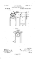
The objects of myinvention'are, first, to so press the bat, as it is delivered from thecotton-gin condenser or elsewhere,that its fibers will not be broken or subjected to any deteriorating in fiuence, and, also, to avoid the danger that is inseparable from the use of a lint room; second, to effect such condensation of the fiber,in the first instance, as will place it in proper condition for ocean and other shipment, and thus obviate the present enormous expense of hauling it to storage warehouses and compresses and, also, of recompressing plantation bales; third, to efiect the compression or baling of the fiber by winding thebat smoothly, or without taugling or twistingits fiberaround a small, removable spindle, so thatthe pressure upon the fiber will constitute the main retaining element or holding means for the completed bale, and so that any light wrapping or covering which will arrest the expansion of the outer layer of the bat, will also prevent all expansion of the rest of said halo, and, also, the fiber will be left in such condition that when said covering has been removed, the rotation of said bale can be reversed and the bat unwound in acontinuous or unbroken sheet,but in a more compressed condition than when it was originally delivered from the condenser; fourth, to so press and wind the bat that its edges, at the ends of the bale, will be open to inspection and sampling throughout its length, without mutilating the bale or disturbing its covering or binding, and, fifth, to provide a machine or press at a moderate cost, which shall be simple in construction and certain or reliable in operation. These objects are accomplished by the mechanism illustrated in the accompanying drawings forming part of this specification, in which the same reference numerals indicate the same or equivalent parts, and in which- Figure lrepresents a vertical, transverse section of the preferred construction of my baling press, showing, also, an endless c011- veying or feeding apron and a portion of a condenser, in connection with said press; Fig. 2, a broken end or side elevation of the press, showing one way of driving the compression beltgFig. 3, a broken, front elevation of the lower part of the press-frame, showing the sliding or adjustable devices for lowering and raising the lower roller; Fig. 4, a horizontal section on the line a: w of Fig. 1, showing gearing for imparting differential speed to the spindle upon which the bale is formed; Fig. 5, a front elevation, of a modified construction of my baling-press, and Fig. 6, an end view of the same.
In Fig. 1 of the drawings the numeral 1 indicates the endless, retaining and compression belt, which passes over the roller 2, around the bale 3, around the roller 4, over the suspension roller 5 and the guide roller 6, around or under the heavy tension-roller 7, and thence upward to the starting point This arrangement of the endless belt forms the loop or bight which receives the fibrous material as it passes between the rollers 2 and 4 and is undergoing the method of baling. The rollers 4, 5 and 6 rotate in ordinary, fixed journal-boxes, not shown, while the roller 2 is journaled at the upper end of the sliding frame 8, which is raised and lowered by the screw-and-bevelwvheel gearing 9, as shown in ing the friction upon said bale. of the bale will, at this stage of the baling method, be proportional to the weight of said Figs. 1 and 3. The heavy tension-roller 7 is supported by the belt 1, except when at its extreme lower position, when its journals rest in the bottoms of the guide grooves 10; also, this idler is raised and lowered by the belt 1, being guided by its journals in said grooves. If desired, however, sliding journal boxes may be employed for the journals of this roller. The endless belt 1 is driven by frictional contact with the rollers 1 and 5, on the ends of which, as shown in Fig. 2, are secured the gear-wheels 1 and 5', which mesh with the smaller gear-wheel 5", so that they may be revolved in the same direction. Power for driving these gear-wheels and rollers may be transmitted from the condenser or other suitable source.
In Fig. 1 of the drawings only so much of the condenser 11 is represented as is necessary to show its connection with the baliugpress by the conveying apron 12, which receives the bat 13 from said condenser and conveys it to said press. This apron passes over and is rotated by the rollers 14, and 15, which are to be driven at the same speed. Assuming the parts in this figure to be in the position shown, except the bale 3, the gin and condenser in operation and the rollers 14 and 15 driven by belts from said condenser, and at the same peripheral speed, the operation will be as fo1lows:--The bat 13 is first started through the opening between the rollers 2 and at and then turned or wound over and over upon itself, in layers, and around a smallangular spindle, 16, until it assumes the form of a small roll, which, at first, is as light and decay as the bat of which it is formed, but which gradually becomes denser, as material is added and the friction increased, until it distends the loop or bight of the belt 1 into circular form and gradually lifts the heavy tension-roller 7, which, being continued, results in the formation of the desired size of bale within said loop or bight of the belt.
The loop or bight of this belt, however, is very little distended or expanded until the size and density of the bale therein become sufficient to overcome the resistance or weight 1 of the roller 7, but, under the continuous accretion of fiber constituting the bat, the bale first merely increases in density, with only little increase in volume, and then it slowly begins to distend said loop or bight, which will result in raising said roller and increas- The density roller and the extent of the frictional surface of the belt against the bale; hence, to con- .tinue to compress the cotton the tension or frictional contact of said belt with the bale should be increased exactly in proportion to the increase in circumference of said bale,
which may be accomplished, for instance, by
applying additional weight, at intervals, to the journals of the tension roller. After the bale has reached the desired size, the hat or sheet of fiber'is'cut 0E and a wrap or cover, of any desired character, placed upon the roller 2 and carried one or more times, preferably twice, around the bale and secured, thus holding the same against unwinding and expansion; then, by discontinuing the rota-' in the loop or bight of the belt 1, I provide and 4.
the removable shaft or spindle 16 and mount the same in movable journal-boxes, 17, which slide upon the guides or ways 18, as shown in end and plan views, respectively, in Figs. 1, 2 The removable part of this spindle is formed with angular ends, 19, which fit into correspondingly-shaped recesses in its adjacent parts, which, on being disconnected, permit of the removal of ,said spindle and the bale wound thereon; also, for the same purpose, said spindle may extend through the bale andrest; at its ends in journal-boxes having removable tops, or it may consist of one or two short, angular, removable journals projecting into and driving an angularly-hollowed spindle or shaft-within the bale, it being only necessary to provide some suitable means for the ready removal of said spindle after the completion of the bale.. As the rollers 14 and 15 operate the conveying or feeding apron at a uniform rate of speed and, consequently, deliver the sheet or bat 13 inuniform quantity into the loop or bight of the belt 1, it follows, as the diameter of the bale 3 gradually increases from the start, oras each" layer of fiber is added thereto, that provision must be made for gradually lessening the rate of rotation of said bale as it increases in diameter, so as to prevent the rupture of said bat and consequent discontinuation of its delivery to the press. This may be accomplished by the differential or variable-speed gear illustrated in Fig.4 of the drawings, in which the shaft 16 is provided with a large metallic disk, 20, which is gripped between the two smaller friction-wheels 21, which are secured to the inner ends of the horizontally-arranged shafts 22 and driven in reverse or opposite directions over the faces of said disk by suitable gearing, 23, connected to the outer ends of said shafts. Intermediate of these shafts is arranged a bifurcated spring, 24, which is suitably secured at its outer end and projects inwardly to a point near said friction-wheels, where its arms or branches, 25, are pivoted to collars,26,surroundingsaidshafts. Nearthe outer end of'this spring, between its arms or branches,is arranged a hand-wheel, 27, which is provided with laterally-projecting screws .in said branches for the purpose of regulating the frictional resistance or gripping contact between said friction-wheels 21 and the large disk 20 As the bale increases in diameter or extent of surface, it moves inward or away from the feed-opening leading into the bight of the belt and carries with it the movable shaft 16, its journal-boxes 17 and said bight of the belt, and also causes the large disk '20 to move in ward and present a grad ually-in creasingcontact surface to the friction-wheels 21, the result being that a uniform peripheral speed is imparted to said bale, an uninterrupted feed of the bat secured, and abalepro' duced in which the leverage against the inner layers of the bat constantly increases, this being due to the fact that each outer layer is more tightly wound by the constant contraction of the next inner layer, whichis drawn inward or toward the center of said bale or the spindle, and by the constantfriction and pressure applied to its outer surface by the belt. This action can be clearly demonstrated by comparison witha map orsheet'ofpaperfirst 'loosely rolled into a hollow cylinder and then rolled from its center into smaller and smaller compass, until it' becomes perfectly solid. Any yielding of one of the inner layers of the bale, by elongation or being wound too tightly around the center of the bale or the spindle, extends through each layer to the outer one, and so continues until the bale is finished, when it is wrapped, covered or bound and removed from the press, as above explained.
The same operation of baling cotton and other loose fibrous materials as that above described is also incident to the modified construction of baling-press illustrated in Figs.
5 and (i of the drawings,in which the belt 1 is held against rotation and the bale formed by the bat or sheet of fiber being wound in lay-' ers around the spindle 16, which will also be capable of removal from the press with the "bale, when the latter is finished, but which is not'mounted in movable journal-boxes. The belt 1 is secured at one end to the bar or rod 28, passes thence beneath the spindle 16 and thence over the guide-roller 29, its lower or free end being provided with the weight or heavy bar 30. Thisarrangement of said belt, as shown in Fig. 6, forms a loop or bight beneath said spindle an'dreceives the thin sheet or hat of fiber, which is first delivered upon IIO the inclined surface'of saidjbelhpa'ssed down this press with variable-speed gearing for regulating the revolutions of the winding spindle as the bale gradually increases in diameter. This may be accomplished by providiug the shaft 16 with a relatively large 3 gear-wheel, 31, which meshes with a smaller gear-wheel, 32, attached to one end of the shaft 33, the other end of said shaft being provided with the bevel-gear wheel 34. This wheel has variable speed imparted thereto by the bevel-gear wheel 35, the power-pulley 36, the intermediate, reversely-arranged, conical pulleys 37, the endless-belt 38, connecting the same, and the pivoted lever 39, which is provided at its outer end with the fork 40 for r 5 shifting the belt upon said conical pulleys.
The inner end of this pivoted lever is provided with the friction disk 4], which, normally, or when the press is empty and in condition for starting, rests against the outer surface of the belt 1 at a. point just beneath the spindle 16. As the sheet or bat of fiber is delivered upon said belt and turned or wound around said spindle, layer upon layer, and as the diameter of the bale being formed gradually increases from the start, the loop or bight of the belt becomesenlarged, presses downward the friction-disk 41 on the inner end of the pivoted lever 39 and raises the outer forked end thereof, which shifts or raises the endless belt 38 over the peripheries of the conical pulleys 37.
The operation of this construction of baling-press in baliug cotton. and other fibrous materials is the same as that incident to the 5 press illustrated in Figs. 1 and 4, which is that a, uniform peripheral speed is imparted to the bale from the commencement of its formation, an unbroken or continuous feed of the sheet or hat of fiber is secured, and a 40 bale is formed in which. each. layer, com menoing with the center one, is simultaneously subjected to compression upon both sides and to the friction of the belt upon its-outer side; also, each outer layer is more tightly wound 5 and compressed by the constant contraction of the next inner layer, which is drawn inward toward the center of the bale or spindle and subjected to the further friction and pressure transmitted through said outer layer. After the bale has been completed, it is wrappedmovered or bound and removed, from the press in the same manner as. above explained.
Having thusfully described my balin g press 5 for cotton and other fibrous materials, its advantages, and the construction, arrangement, or combination of its several parts, what I claim. as new is 1. In a baling-press for cotton and other loose fibrous materials,thecombination, with feeding mechanism and a belt arranged to form an expansible loop or bight, of. means for subjecting said materials to simultaneous friction and pressure within said loop or bight, substantially as described.
2. Ina baling press for cotton and other loose fibrous materials, the combination, with feeding mechanism and a belt having an expansible loop or bight, of means for rotating and winding said materials within said loop or bight, substantially as described.
3. In a baling-press for cotton and other loose fibrous materials, the combination, with feeding mechanism and a belt arranged to form an expansible loop or bight, of means for winding said material from the center of the bale, layer upon layer, and for simultaneously subjecting the same to friction and pressure, substantially as described.
4. In a baling-press for cotton and other loose fibrous materials, the combination, with feeding mechanism and a belt arranged to form an expansible loop or bight, of means for subjecting said materials to simultaneous friction and pressure within said loop or bight, said means consisting of a weight at tached to said belt, and a revolving spindle arranged within said loop or bight,,substan tially as described.
5. In a baling-press for cotton and other loose fibrous materials, the combination, with feeding mechanism and a belt arranged to form an expansibl e loop or bight, of a weight connecting-with said belt, a spindle arranged within said loop or bight and means for imparting variable speed to said spindle, substantially as described.
6. In a baling-press for cotton and other loose fibrous materials, the combination, with feeding mechanism, an endless, traveling belt arranged to form an expansible loop or bight, rollers for supporting and guiding said belt, 1 and the heavy tension-roller arranged within said belt, of means for imparting motion to said belt and, also, for forming a bale within 1 the loop or bight of said belt, substantially as described.
7. In a baling-press for cotton and other loose fibrous materials, the combination, with feeding mechanism, an endless, traveling belt arranged to form an expausible loop or bight,
V rollers for supporting and guiding said belt,
and the heavy tension-roller arranged within said belt, of means for imparting motion to said belt and, also, for forming a bale within the loop or bight of said belt, said means consisting, respectively, of the gear-wheels 4:, 5' and 5 and. the revolving spindle l6, substan- 1 tially as described.
8. In a baling-press for cotton and other i loose fibrous materials, the combination, with feeding mechanism, an endless, traveling belt arranged to form an expausible loopor bight,
rollers for supporting and guiding said belt,
and the heavy tension-roller arranged within 1 said belt, of means for imparting motion to j said belt and, also, for forming a bale within the loop or bight of said belt, said meansconsisting, respectively, of the gear-wheelst, 5
and 5 andthe revoluble andslidable spindle 16, substantially as described.
9. In a billing-press for cotton and other loose fibrous materials, the combination, with feeding mechanism, an endless, traveling belt arranged to form an expansiblc loop or bight, rollers for supporting and guiding said belt, and the heavy tension-roller arranged within said belt, of means for forming a bale within said loop or bight and means for permitting of the removal of said bale therefrom, substantially as described.
10. In a baling-press for cotton and other loose fibrous materials, the combination, with feeding mechanism, an endless, traveling belt arranged to form an expansible loop or bight, rollers for supporting and guiding said belt, and the heavy tension-roller arranged within said belt, of means for forming a bale within said loop or bight and means for permitting of the removal of said bale therefrom, said means consisting, respectively, of the revoluble and removable spindle 16, and of the vertically-sliding frame 8 having the roller 2 at its upper end, and the screw-and-bevel-wheelgearing 9, substantially as described.
11. In a baling-press for cotton and other fibrous materials, the combination, \vith feeding mechanism, an endless, weighted 'belt,-arranged to form an expansible loop or bight, of a spindle arranged within said loop or bight and means for imparting variable speed to said spindle, said means consisting of the movable journal-boxes 17, the disk 20, the friction wheels 21 and devices for revolving the latter, substantially as described.
12. In a baling-press for cotton and other fibrous materials, the combination, with feeding mechanism, an endless, weighted traveling belt, arranged to form an expansible loop or bight, of a spindle arranged within said loop or bight and means for imparting variable speed to said spindle, said means consisting of the movable journal-boxes 17, the disk 20, the friction wheels 21, the shafts 22, the gearing 23, the adjustable bifurcated-spring 24, and means for connecting the same to said shafts, substantially as described.
13. A balingpress for cotton and other fibrous materials, provided with a weighted traveling belt arranged to form an expansible loop or bight and for subjecting said materials to simultaneous friction and pressure, in combination with means for feeding a thin sheet or hat of said materials into the loop or bight of said belt, substantially as described.
14. A baling-press for cotton and other fibrous materials, provided with a weighted traveling belt arranged to form an expansible loop or bight and for subjecting said materials to simultaneous friction and pressure,
in combination with an endless, conveying or fibrous materials, provided'with a weighted belt arranged to form an expansible loop or bight and for subjecting said materials to simultaneous friction and pressure, in combination with the removable shaft orspindle 16, the rollers 14 and 15, and the endless conveying-apron 12, substantially as described.
16. In a baling-press for cotton and other loose fibrous materials, the combination, with the endless traveling belt 1 formed with the loop or bight, the rollers 2and 4, the suspension roller 5, the guide-roller 6, the "tensionroller 7, the endless conveying or feeding apron 12 and the rollers 14 and 15, substantially as described.
17. In a baling-press for cotton and other loose fibrous materials, the combination, with the endless belt 1 formed with the loop or bight, the shaft or spindle 16 arranged within said loop or bight, the rollers 2 and 4, the suspension roller 5, the guide roller 6, the tension roller 7, the endless conveying or feeding apron 12 and the rollers 14 and 15, substantially as described.
18. In a baling-press for cotton and other loose fibrous materials, the combination, with the endless belt 1 formed with the loop or bight, the shaft or spindle 16 arranged within said loop or bight, the vertically-movable roller 2, the roller 4 above and in close proximity thereto, the suspension roller 5, the guide-roller 6, the tension-roller 7, the endless, conveying or feeding apron 12 and the rollers 14 and 15, substantially as described.
19. In a baling-pressfor cotton and other loose fibrous materials, the combination, with the endless belt 1 formed with the loop or bight, the shaft or spindle 16 arranged within said loop or bight, the horizontally-movable journal-boxes 17, within which said shaft or spindle is mounted, the vertically-movable roller 2, the roller 4 above and in close proximity thereto, the suspension roller 5, the guide-roller 6, the tension-roller 7, the endless, conveying or feeding apron 12 and the rollers 14 and 15, substantially as described.
In testimony whereof I affixmysignature-in presence of two witnesses.
JOHN w. GRAVES.
Witnesses:
JAMES M. POLLARD, ToM R. STUART.
ICO
Publications (1)
| Publication Number | Publication Date |
|---|---|
| US510388A true US510388A (en) | 1893-12-05 |
Family
ID=2579215
Family Applications (1)
| Application Number | Title | Priority Date | Filing Date |
|---|---|---|---|
| US510388D Expired - Lifetime US510388A (en) | Thomas lanigan |
Country Status (1)
| Country | Link |
|---|---|
| US (1) | US510388A (en) |
Cited By (1)
| Publication number | Priority date | Publication date | Assignee | Title |
|---|---|---|---|---|
| US20080124839A1 (en) * | 2006-11-27 | 2008-05-29 | Lintec Corporation | Adhesive Composition, Adhesive Sheet and Production Process for Semiconductor Device |
-
0
- US US510388D patent/US510388A/en not_active Expired - Lifetime
Cited By (1)
| Publication number | Priority date | Publication date | Assignee | Title |
|---|---|---|---|---|
| US20080124839A1 (en) * | 2006-11-27 | 2008-05-29 | Lintec Corporation | Adhesive Composition, Adhesive Sheet and Production Process for Semiconductor Device |
Similar Documents
| Publication | Publication Date | Title |
|---|---|---|
| US2649133A (en) | Method and device for producing high-pressure tubes of hardening materials as cement | |
| US546009A (en) | John w | |
| US510388A (en) | Thomas lanigan | |
| US862105A (en) | Method of forming round bales. | |
| US836414A (en) | Machine for making plaster of paris bandages. | |
| US510385A (en) | Jane lanigan | |
| US1145630A (en) | Method of forming cotton and the like into bales. | |
| US510386A (en) | And thomas lanigan | |
| US642099A (en) | Roller baling-press. | |
| US510387A (en) | And thomas lanigan | |
| US604012A (en) | anderson | |
| US28256A (en) | Machinery for winding laps | |
| US798969A (en) | Machine for reeling edible fibrous material and grain. | |
| USRE11604E (en) | graves | |
| US567548A (en) | Cotton baling press | |
| US699114A (en) | Roller-press. | |
| US307119A (en) | Wilson | |
| US446128A (en) | brows | |
| RU2284098C1 (en) | Roll-type baler for bast-fiber crops | |
| US932430A (en) | Manufacture of paper and apparatus therefor. | |
| US987790A (en) | Bat-former. | |
| US665347A (en) | Cotton-compress. | |
| US633708A (en) | Cotton-baling press. | |
| US5632A (en) | Improvement in cotton-presses | |
| US596255A (en) | Grass curling and baling press |