US5102235A - Linear motion bearing - Google Patents
Linear motion bearing Download PDFInfo
- Publication number
- US5102235A US5102235A US07/639,558 US63955891A US5102235A US 5102235 A US5102235 A US 5102235A US 63955891 A US63955891 A US 63955891A US 5102235 A US5102235 A US 5102235A
- Authority
- US
- United States
- Prior art keywords
- end cap
- return track
- return
- linear motion
- elements
- Prior art date
- Legal status (The legal status is an assumption and is not a legal conclusion. Google has not performed a legal analysis and makes no representation as to the accuracy of the status listed.)
- Expired - Lifetime
Links
- 238000005096 rolling process Methods 0.000 claims description 30
- 238000007789 sealing Methods 0.000 claims description 10
- 229920006351 engineering plastic Polymers 0.000 claims description 3
- 239000004952 Polyamide Substances 0.000 claims description 2
- 229920002647 polyamide Polymers 0.000 claims description 2
- 239000004417 polycarbonate Substances 0.000 claims description 2
- 229920000515 polycarbonate Polymers 0.000 claims description 2
- 229920006324 polyoxymethylene Polymers 0.000 claims description 2
- 230000000295 complement effect Effects 0.000 claims 3
- 238000005553 drilling Methods 0.000 description 5
- 230000003134 recirculating effect Effects 0.000 description 5
- 239000000463 material Substances 0.000 description 4
- 230000000712 assembly Effects 0.000 description 3
- 238000000429 assembly Methods 0.000 description 3
- 238000004519 manufacturing process Methods 0.000 description 3
- 238000000034 method Methods 0.000 description 3
- 238000004026 adhesive bonding Methods 0.000 description 2
- 230000002411 adverse Effects 0.000 description 2
- 238000013459 approach Methods 0.000 description 2
- 238000005304 joining Methods 0.000 description 2
- 239000004033 plastic Substances 0.000 description 2
- 229920003023 plastic Polymers 0.000 description 2
- 230000007704 transition Effects 0.000 description 2
- 238000003466 welding Methods 0.000 description 2
- 238000010276 construction Methods 0.000 description 1
- 238000011109 contamination Methods 0.000 description 1
- 238000005520 cutting process Methods 0.000 description 1
- -1 for example Polymers 0.000 description 1
- 238000003754 machining Methods 0.000 description 1
- 230000013011 mating Effects 0.000 description 1
- 239000002184 metal Substances 0.000 description 1
- 238000000465 moulding Methods 0.000 description 1
- 238000003825 pressing Methods 0.000 description 1
- 230000000717 retained effect Effects 0.000 description 1
- 238000010079 rubber tapping Methods 0.000 description 1
- 239000003351 stiffener Substances 0.000 description 1
Images


Classifications
-
- F—MECHANICAL ENGINEERING; LIGHTING; HEATING; WEAPONS; BLASTING
- F16—ENGINEERING ELEMENTS AND UNITS; GENERAL MEASURES FOR PRODUCING AND MAINTAINING EFFECTIVE FUNCTIONING OF MACHINES OR INSTALLATIONS; THERMAL INSULATION IN GENERAL
- F16C—SHAFTS; FLEXIBLE SHAFTS; ELEMENTS OR CRANKSHAFT MECHANISMS; ROTARY BODIES OTHER THAN GEARING ELEMENTS; BEARINGS
- F16C29/00—Bearings for parts moving only linearly
- F16C29/04—Ball or roller bearings
- F16C29/06—Ball or roller bearings in which the rolling bodies circulate partly without carrying load
- F16C29/0633—Ball or roller bearings in which the rolling bodies circulate partly without carrying load with a bearing body defining a U-shaped carriage, i.e. surrounding a guide rail or track on three sides
- F16C29/0652—Ball or roller bearings in which the rolling bodies circulate partly without carrying load with a bearing body defining a U-shaped carriage, i.e. surrounding a guide rail or track on three sides whereby the return paths are at least partly defined by separate parts, e.g. covers attached to the legs of the main body of the U-shaped carriage
- F16C29/0654—Ball or roller bearings in which the rolling bodies circulate partly without carrying load with a bearing body defining a U-shaped carriage, i.e. surrounding a guide rail or track on three sides whereby the return paths are at least partly defined by separate parts, e.g. covers attached to the legs of the main body of the U-shaped carriage with balls
- F16C29/0657—Ball or roller bearings in which the rolling bodies circulate partly without carrying load with a bearing body defining a U-shaped carriage, i.e. surrounding a guide rail or track on three sides whereby the return paths are at least partly defined by separate parts, e.g. covers attached to the legs of the main body of the U-shaped carriage with balls with two rows of balls, one on each side of the rail
-
- F—MECHANICAL ENGINEERING; LIGHTING; HEATING; WEAPONS; BLASTING
- F16—ENGINEERING ELEMENTS AND UNITS; GENERAL MEASURES FOR PRODUCING AND MAINTAINING EFFECTIVE FUNCTIONING OF MACHINES OR INSTALLATIONS; THERMAL INSULATION IN GENERAL
- F16C—SHAFTS; FLEXIBLE SHAFTS; ELEMENTS OR CRANKSHAFT MECHANISMS; ROTARY BODIES OTHER THAN GEARING ELEMENTS; BEARINGS
- F16C29/00—Bearings for parts moving only linearly
- F16C29/04—Ball or roller bearings
- F16C29/06—Ball or roller bearings in which the rolling bodies circulate partly without carrying load
- F16C29/0602—Details of the bearing body or carriage or parts thereof, e.g. methods for manufacturing or assembly
- F16C29/0609—Details of the bearing body or carriage or parts thereof, e.g. methods for manufacturing or assembly of the ends of the bearing body or carriage where the rolling elements change direction, e.g. end caps
-
- F—MECHANICAL ENGINEERING; LIGHTING; HEATING; WEAPONS; BLASTING
- F16—ENGINEERING ELEMENTS AND UNITS; GENERAL MEASURES FOR PRODUCING AND MAINTAINING EFFECTIVE FUNCTIONING OF MACHINES OR INSTALLATIONS; THERMAL INSULATION IN GENERAL
- F16C—SHAFTS; FLEXIBLE SHAFTS; ELEMENTS OR CRANKSHAFT MECHANISMS; ROTARY BODIES OTHER THAN GEARING ELEMENTS; BEARINGS
- F16C29/00—Bearings for parts moving only linearly
- F16C29/04—Ball or roller bearings
- F16C29/06—Ball or roller bearings in which the rolling bodies circulate partly without carrying load
- F16C29/0602—Details of the bearing body or carriage or parts thereof, e.g. methods for manufacturing or assembly
- F16C29/0611—Details of the bearing body or carriage or parts thereof, e.g. methods for manufacturing or assembly of the return passages, i.e. the passages where the rolling elements do not carry load
-
- F—MECHANICAL ENGINEERING; LIGHTING; HEATING; WEAPONS; BLASTING
- F16—ENGINEERING ELEMENTS AND UNITS; GENERAL MEASURES FOR PRODUCING AND MAINTAINING EFFECTIVE FUNCTIONING OF MACHINES OR INSTALLATIONS; THERMAL INSULATION IN GENERAL
- F16C—SHAFTS; FLEXIBLE SHAFTS; ELEMENTS OR CRANKSHAFT MECHANISMS; ROTARY BODIES OTHER THAN GEARING ELEMENTS; BEARINGS
- F16C29/00—Bearings for parts moving only linearly
- F16C29/08—Arrangements for covering or protecting the ways
- F16C29/084—Arrangements for covering or protecting the ways fixed to the carriage or bearing body movable along the guide rail or track
Definitions
- the present invention relates to anti-friction linear motion bearings and, more particularly, to linear motion bearing assemblies containing a plurality of rolling elements in recirculating load and return tracks.
- Linear motion bearing assemblies are well known in the art and are used extensively in a wide variety of machines, machine tools, transfer systems and other equipment where one part is to be moved longitudinally with respect to another.
- These assemblies may comprise an inverted substantially U-shaped bearing carriage mounted astride a modified Y-beam, I-beam or T-beam shaped rail.
- a plurality of pairs of load bearing and return tracks are provided in association with the carriage for a plurality of recirculating rolling elements, such as for example balls or rollers. These rolling elements travel alternately through load bearing tracks and return tracks to facilitate movement of the carriage along the rail with minimum friction.
- End caps are usually located on both longitudinal ends of the carriage and may have turnarounds formed therein for transferring the recirculating rolling elements from load bearing tracks to return tracks.
- the turnarounds typically comprise a semi-toroidal shaped track connecting a load bearing track to a return track.
- an inner guide may be provided at the center of the semi-toroid to smooth the movement of the rolling elements around the curved position from the load bearing track to the return track and to prevent the rolling elements from bunching up in the turns.
- These end caps are usually formed out of plastic material using molds which form the curved tracks of the turnaround integral with the end cap.
- Bores or channels are typically cut or drilled into the carriage body to form the return tracks for the recirculating rolling elements. See, for example, U.S. Pat. No. 4,797,012.
- the return tracks are formed by drilling or cutting bores or grooves conforming in size to the dimensions of the rolling elements directly into the bearing carriage within the depending legs of the U-shaped structure. See, for example, U.S. Pat. No. 4,932,067. This procedure is time consuming, requires special precision grinding and/or drilling instrumentation and greatly increases the expense involved in the manufacture and assembly of linear motion bearings. Also, where the rolling elements are of small diameter, extreme care must be taken to insure that the bores are accurate and properly aligned.
- a linear motion bearing assembly having return tracks substantially around the outside of the depending legs of the bearing carriage wherein the end caps and a portion of the return tracks are integrally formed in two interfitting elements and mounted on the bearing carriage without the need for mounting holes to be drilled therein.
- the combination end caps/return track elements are preferably identical images of each other permitting the use of a single mold for both elements.
- Turnarounds are integrally formed in each end cap to interconnect the inner load bearing tracks and the outside return tracks.
- an inner axis for the turnaround also may be formed with the end cap to aid in the transition of the rolling elements from load bearing tracks to return tracks.
- a seal may be added to the bearing carriage and interlocked with the end cap/return track elements.
- This structure provides a dependable linear motion bearing assembly that is easy to fabricate with a minimum number of moldable parts and eliminates the need for excessive drilling and/or tapping of the bearing carriage.
- FIG. 1 is an expanded perspective view of the linear motion bearing assembly in accordance with a preferred embodiment of the present invention.
- FIG. 2 is a perspective view of interlocking end cap/return track elements in accordance with the embodiment of FIG. 1.
- FIG. 3 is a perspective view of the bearing carriage of the embodiment shown in FIG. 1.
- FIG. 4 is a longitudinal view in cross section of an assembled linear motion bearing mounted on a rail.
- FIGS. 5-7 are views of a seal in accordance with the present invention.
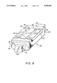
- FIG. 8 is a perspective view of a complete linear motion bearing assembly in accordance with the present invention.
- an inverted substantially U-shaped bearing carriage 20 is shown having an internal longitudinal groove 22 formed in each depending leg 24. These grooves serve as the load bearing paths for rolling elements 26 (best shown in FIG. 4). External grooves 28 are formed in each depending leg 24 proximate the bottom edge to a depth approximating the diameter of rolling elements 26. These grooves 28 serve as the internal surface of return paths for rolling elements 26. In the embodiment shown in FIG. 1, the external grooves 28 are formed in the lower outside corner of depending legs 24 to facilitate ease of manufacture and to avoid expanding the width of the bearing carriage 20 to compensate for the outside return path. This position also allows the groove 28 to be extruded as part of the bearing carriage 20 thus avoiding the need for elaborate machining operations. It is contemplated, however, that the external groove 28 could be formed solely in the outside surface of depending legs 24 at some location not proximate the base and those embodiments are within the scope of the present invention.
- the end caps 32 and an outer portion of the return tracks 34 are integrally formed together in mirror image such that a single mold may be used to form both left and right halves of the combination end caps and outer return track portions (hereinafter referred to as the end cap/return track elements 36).
- the entire longitudinal length of the outer portion of a return track 34 is formed integrally with the right side of the end cap 32.
- Attaching means preferably in the form of integral locking means is provided to join the two end cap/return track elements 36 together.
- a projection 38 with detent 40 is formed at a longitudinal end of the return track portion 34 opposite end cap 32.
- a mating slot 42 is formed through a left wall of end cap 32 terminating in cutout 44 dimensioned to engage and hold a corresponding projection 38 and detent 40 when opposing end cap/return track elements 36 are aligned on the bearing carriage 20 and joined.
- Other known locking means are well known in the art including bolts, gluing, heat sealing, welding, etc. These other locking means are contemplated by the present invention.
- End cap/return track elements 36 are each provided with turnaround structure 46 dimensioned to conduct the rolling elements 26 between load bearing paths and return paths.
- This turnaround structure 46 may be semi-toroidal in shape and interconnects the outside return path with the load bearing path.
- Inner guides (not shown) also may be provided to ease the transition of the rolling elements 26 between the respective paths.
- Outer return tracks 34 have a rounded L-shape as shown in FIGS. 1-2 and substantially conform to the sidewalls of the end caps 32.
- the uppermost portion of the L-shaped outer return track 34 is preferably dimensioned to fit flush with the overhang 48 in the bearing carriage 20. In this manner, a smooth uninterrupted sidewall is presented.
- the yoke of the L-shaped outer return track 34 is rounded to substantially conform to the dimensions of the rolling elements 26 designed to pass therethrough. This rounded portion in combination with external grooves 28 serve to form the complete return track.
- a second projection 48 is provided in the horizontal portion of the L-shaped outer return track 34 proximate projection 38.
- This second projection 48 interfits with cavity 50 formed in end cap 32.
- Bearing carriage 20 is provided with longitudinal channels 64 which serve to align end cap/return track elements 36 on the carriage 20 by interfitting with projections 66 formed on the top surface of end cap/return track elements 36.
- the end cap/ return track elements 36 are molded from an engineering plastic, for example, polyacetals, polycarbonates, polyamides, etc.
- an engineering plastic for example, polyacetals, polycarbonates, polyamides, etc.
- a sealing means 52 can be added to the linear motion bearing assembly to shield access to the recirculating tracks.
- One embodiment of such sealing means 52 is shown in FIGS. 5-7 and comprises two end portions 54 interconnected by flexible, self adjusting longitudinal sections 56.
- the end portions 54 snap fit securely to the end caps 32 of the linear motion bearing and stretch longitudinal sections 56 to adjustably fit along the bottom of the bearing carriage 20.
- the snap fit attachment is accomplished by means of pressing projections 58 in end portions 54 into corresponding slots 60 in end caps 32.
- Other joining methods such as, for example, gluing, bolting, welding etc. are well known in the art and are contemplated by the present invention.
- These longitudinal sections serve to further protect the load bearing tracks from external contamination during operation of the linear motion bearing.
- longitudinal sections 56 are retained within a channel 62 formed in the horizontal longitudinal edge of outer return track 34.
- the sealing means 52 can be fabricated from a wide variety of materials including plastics and rubber materials.
- the seal may incorporate metal stiffeners in the end portion 54 in order to give the seal further rigidity and sealing protection.
- the linear motion bearing in accordance with this embodiment is assembled by approximating opposing end cap/return track elements 36 around bearing carriage 20 and aligning projections 38 with slots 42, projections 66 with channels 64 and projections 48 with cavity 50.
- the bearing carriage 20 Prior to final joining, the bearing carriage 20 is positioned on rail 68 and rolling elements 26 are loaded into the load bearing and return tracks.
- the opposing aligned end cap/return track elements 36 are locked together forming a completed linear motion bearing assembly.
- the seal 62 is positioned with the longitudinal sections 56 in longitudinal channels 64 and the end portions 54 proximate the end caps 32. The end portions 54 are then snap fitted into the end caps 32 as discussed above.
Landscapes
- Engineering & Computer Science (AREA)
- General Engineering & Computer Science (AREA)
- Mechanical Engineering (AREA)
- Bearings For Parts Moving Linearly (AREA)
Abstract
Description
Claims (15)
Priority Applications (5)
| Application Number | Priority Date | Filing Date | Title |
|---|---|---|---|
| US07/639,558 US5102235A (en) | 1991-01-10 | 1991-01-10 | Linear motion bearing |
| CA002058558A CA2058558C (en) | 1991-01-10 | 1991-12-30 | Linear motion bearing |
| MX9200082A MX9200082A (en) | 1991-01-10 | 1992-01-09 | MOUNTING OF LINEAR MOVEMENT BEARING. |
| DE69222443T DE69222443T2 (en) | 1991-01-10 | 1992-01-10 | Bearings for linear movements |
| EP92100336A EP0494682B1 (en) | 1991-01-10 | 1992-01-10 | Linear motion bearing |
Applications Claiming Priority (1)
| Application Number | Priority Date | Filing Date | Title |
|---|---|---|---|
| US07/639,558 US5102235A (en) | 1991-01-10 | 1991-01-10 | Linear motion bearing |
Publications (1)
| Publication Number | Publication Date |
|---|---|
| US5102235A true US5102235A (en) | 1992-04-07 |
Family
ID=24564598
Family Applications (1)
| Application Number | Title | Priority Date | Filing Date |
|---|---|---|---|
| US07/639,558 Expired - Lifetime US5102235A (en) | 1991-01-10 | 1991-01-10 | Linear motion bearing |
Country Status (5)
| Country | Link |
|---|---|
| US (1) | US5102235A (en) |
| EP (1) | EP0494682B1 (en) |
| CA (1) | CA2058558C (en) |
| DE (1) | DE69222443T2 (en) |
| MX (1) | MX9200082A (en) |
Cited By (28)
| Publication number | Priority date | Publication date | Assignee | Title |
|---|---|---|---|---|
| US5200014A (en) * | 1990-12-14 | 1993-04-06 | Roger Peters | Method of manufacturing a linear slide |
| US5265963A (en) * | 1991-05-13 | 1993-11-30 | Thk Co., Ltd. | Side cover fixing structure for linear motion bearing |
| US5275492A (en) * | 1991-05-16 | 1994-01-04 | Thk Co., Ltd. | Linear motion slide unit |
| USD344964S (en) | 1992-10-14 | 1994-03-08 | Nippon Bearing Co., Ltd. | Ball bearing for rectilinear sliding |
| US5308165A (en) * | 1991-03-29 | 1994-05-03 | Nippon Thompson Co., Ltd. | End block of a linear motion guide unit |
| USD351848S (en) | 1993-01-13 | 1994-10-25 | Nippon Bearing Co., Ltd. | Ball bearing for rectilinear sliding |
| US5488771A (en) * | 1994-03-09 | 1996-02-06 | Advanced Engineering Systems, Operations & Products Inc. | Method for manufacturing externally pressurized bearing assemblies |
| US6170986B1 (en) * | 1999-04-07 | 2001-01-09 | Chieftech Precision Co., Ltd. | Linear motion rolling guide device |
| US6369875B1 (en) * | 1999-01-26 | 2002-04-09 | Sharp Kabushiki Kaisha | Slidable assembly including slider pieces with an upper and lower part |
| US20020102035A1 (en) * | 2001-01-30 | 2002-08-01 | Nippon Thompson Co., Ltd. | Linear motion guide unit |
| US6550969B1 (en) * | 1998-07-31 | 2003-04-22 | Schneeberger Holding Ag | Carriage for linear guiding device |
| US6558039B2 (en) * | 2000-05-24 | 2003-05-06 | Hiwin Technologies Corp. | Linear guide way |
| US20050105834A1 (en) * | 2002-06-21 | 2005-05-19 | Ina-Schaeffler Kg | Linear rolling bearing |
| US20060137485A1 (en) * | 2004-11-30 | 2006-06-29 | Nsk Ltd. | Linear motion device |
| US20070263950A1 (en) * | 2006-05-15 | 2007-11-15 | Hiwin Technologies Corp. | Linear motion guide apparatus having ball retaining device |
| US20080103028A1 (en) * | 2006-11-01 | 2008-05-01 | Advanced Motion Technologies Corp. | Slider for a linear slide system |
| EP1845272A3 (en) * | 2006-04-11 | 2008-07-23 | SBC Linear Co.,Ltd. | End-plate for linear motion slider and linear motion slider in use with the end-plate |
| US20090008882A1 (en) * | 2007-07-03 | 2009-01-08 | Schaeffler Kg | Gasket for a hydrostatic linear guide |
| US20090161996A1 (en) * | 2004-11-15 | 2009-06-25 | Thk Co., Ltd. | Motion guide device, table apparatus, and damping method for motion guide device |
| US20110033141A1 (en) * | 2009-08-04 | 2011-02-10 | Tsung-Jen Chen | Circulating System for a Linear Guideway |
| EP1600647A3 (en) * | 2004-05-28 | 2011-03-16 | Nippon Thompson Co., Ltd. | Linear motion guide unit |
| US20130044968A1 (en) * | 2011-08-19 | 2013-02-21 | Nippon Thompson Co., Ltd. | Miniature linear motion guide unit |
| US20150093056A1 (en) * | 2013-09-27 | 2015-04-02 | Ome Technology Co., Ltd. | Linear guideway and retainer thereof |
| US20170259925A1 (en) * | 2016-03-14 | 2017-09-14 | Airbus Defence and Space GmbH | Seat fastening device |
| US9863470B2 (en) * | 2014-03-31 | 2018-01-09 | Thk Co., Ltd. | Motion guide apparatus and method for manufacturing the same |
| US20180298946A1 (en) * | 2015-12-23 | 2018-10-18 | Airbus Operations Gmbh | Securing device and linear guiding mechanism |
| US11147372B2 (en) * | 2018-04-23 | 2021-10-19 | Chieftek Precision Co., Ltd. | Micro linear slide rail assembly and slider thereof |
| US11384819B2 (en) * | 2017-08-16 | 2022-07-12 | Ewellix AB | Linear module |
Families Citing this family (10)
| Publication number | Priority date | Publication date | Assignee | Title |
|---|---|---|---|---|
| DE19538665A1 (en) * | 1995-10-17 | 1997-04-24 | Star Gmbh | Linear guide equipment with circulating rollers inside traveller body |
| EP0769627B1 (en) | 1995-10-17 | 2000-08-02 | Deutsche Star GmbH | Linear guiding device |
| DE19920477B4 (en) * | 1999-05-04 | 2007-06-21 | Chieftech Precision Co., Ltd. | Rolling device for linear movements |
| JP4564198B2 (en) | 2001-03-29 | 2010-10-20 | 日本トムソン株式会社 | Linear motion guidance unit |
| DE10227716A1 (en) * | 2002-06-21 | 2004-01-08 | Ina-Schaeffler Kg | Linear roller bearing with return pipe |
| DE10227688A1 (en) * | 2002-06-21 | 2004-01-08 | Ina-Schaeffler Kg | linear bearings |
| DE102006062105B4 (en) * | 2006-12-23 | 2010-12-02 | Precision Motion Industries Inc., Shen Kang Hsiang | Slider for a sliding system |
| DE102009017174B4 (en) | 2009-04-09 | 2011-03-31 | Ab Skf | Linear carriage, linear guide and method for mounting a linear carriage |
| DE102009017173B4 (en) | 2009-04-09 | 2012-04-19 | Aktiebolaget Skf | Linear carriage and linear guide |
| DE102014104468B4 (en) * | 2014-03-28 | 2017-10-05 | Hiwin Technologies Corp. | Linear drive system |
Citations (13)
| Publication number | Priority date | Publication date | Assignee | Title |
|---|---|---|---|---|
| US4420193A (en) * | 1981-08-11 | 1983-12-13 | Hiroshi Teramachi | Linear ball bearing unit |
| US4475776A (en) * | 1982-03-19 | 1984-10-09 | Hiroshi Teramachi | Linear slide bearing |
| US4632573A (en) * | 1984-10-11 | 1986-12-30 | Tsubakimoto Precision Products Co., Ltd. | Linear motion ball bearing |
| US4637739A (en) * | 1984-11-10 | 1987-01-20 | Nippon Seiko Kabushiki Kaisha | Linear guide device |
| US4662763A (en) * | 1984-04-28 | 1987-05-05 | Tsubakimoto Precision Products Co., Ltd. | Tubular bearing for linear motion |
| US4674893A (en) * | 1985-03-08 | 1987-06-23 | Hiroshi Teramachi | Linear-motion bearing unit |
| US4746228A (en) * | 1985-12-30 | 1988-05-24 | Nippon Thompson Co., Ltd. | Linear motion rolling contract bearing assembly using a roller having a truncated dome end |
| US4797012A (en) * | 1987-11-12 | 1989-01-10 | Nippon Thompson Co., Ltd. | Linear motion rolling guide unit |
| US4869600A (en) * | 1987-11-30 | 1989-09-26 | Tsubakimoto Precision Products Co., Ltd. | Linear motion ball bearing |
| US4932067A (en) * | 1989-05-30 | 1990-06-05 | Thomson Industries, Inc. | Linear motion bearing |
| US4932279A (en) * | 1987-10-16 | 1990-06-12 | Nippon Seiko Kabushiki Kaisha | Feed screw apparatus |
| US4974971A (en) * | 1989-09-26 | 1990-12-04 | Nippon Thompson Co., Ltd. | Small-sized linear motion guide assembly |
| US4983049A (en) * | 1989-01-25 | 1991-01-08 | Marc Lecomte | Linear precision guide |
Family Cites Families (1)
| Publication number | Priority date | Publication date | Assignee | Title |
|---|---|---|---|---|
| DE3422444A1 (en) * | 1984-06-16 | 1985-12-19 | Skf Gmbh | Telescopic unit |
-
1991
- 1991-01-10 US US07/639,558 patent/US5102235A/en not_active Expired - Lifetime
- 1991-12-30 CA CA002058558A patent/CA2058558C/en not_active Expired - Fee Related
-
1992
- 1992-01-09 MX MX9200082A patent/MX9200082A/en not_active IP Right Cessation
- 1992-01-10 DE DE69222443T patent/DE69222443T2/en not_active Expired - Fee Related
- 1992-01-10 EP EP92100336A patent/EP0494682B1/en not_active Expired - Lifetime
Patent Citations (13)
| Publication number | Priority date | Publication date | Assignee | Title |
|---|---|---|---|---|
| US4420193A (en) * | 1981-08-11 | 1983-12-13 | Hiroshi Teramachi | Linear ball bearing unit |
| US4475776A (en) * | 1982-03-19 | 1984-10-09 | Hiroshi Teramachi | Linear slide bearing |
| US4662763A (en) * | 1984-04-28 | 1987-05-05 | Tsubakimoto Precision Products Co., Ltd. | Tubular bearing for linear motion |
| US4632573A (en) * | 1984-10-11 | 1986-12-30 | Tsubakimoto Precision Products Co., Ltd. | Linear motion ball bearing |
| US4637739A (en) * | 1984-11-10 | 1987-01-20 | Nippon Seiko Kabushiki Kaisha | Linear guide device |
| US4674893A (en) * | 1985-03-08 | 1987-06-23 | Hiroshi Teramachi | Linear-motion bearing unit |
| US4746228A (en) * | 1985-12-30 | 1988-05-24 | Nippon Thompson Co., Ltd. | Linear motion rolling contract bearing assembly using a roller having a truncated dome end |
| US4932279A (en) * | 1987-10-16 | 1990-06-12 | Nippon Seiko Kabushiki Kaisha | Feed screw apparatus |
| US4797012A (en) * | 1987-11-12 | 1989-01-10 | Nippon Thompson Co., Ltd. | Linear motion rolling guide unit |
| US4869600A (en) * | 1987-11-30 | 1989-09-26 | Tsubakimoto Precision Products Co., Ltd. | Linear motion ball bearing |
| US4983049A (en) * | 1989-01-25 | 1991-01-08 | Marc Lecomte | Linear precision guide |
| US4932067A (en) * | 1989-05-30 | 1990-06-05 | Thomson Industries, Inc. | Linear motion bearing |
| US4974971A (en) * | 1989-09-26 | 1990-12-04 | Nippon Thompson Co., Ltd. | Small-sized linear motion guide assembly |
Cited By (42)
| Publication number | Priority date | Publication date | Assignee | Title |
|---|---|---|---|---|
| US5200014A (en) * | 1990-12-14 | 1993-04-06 | Roger Peters | Method of manufacturing a linear slide |
| US5308165A (en) * | 1991-03-29 | 1994-05-03 | Nippon Thompson Co., Ltd. | End block of a linear motion guide unit |
| US5265963A (en) * | 1991-05-13 | 1993-11-30 | Thk Co., Ltd. | Side cover fixing structure for linear motion bearing |
| US5275492A (en) * | 1991-05-16 | 1994-01-04 | Thk Co., Ltd. | Linear motion slide unit |
| USD344964S (en) | 1992-10-14 | 1994-03-08 | Nippon Bearing Co., Ltd. | Ball bearing for rectilinear sliding |
| USD351848S (en) | 1993-01-13 | 1994-10-25 | Nippon Bearing Co., Ltd. | Ball bearing for rectilinear sliding |
| US5488771A (en) * | 1994-03-09 | 1996-02-06 | Advanced Engineering Systems, Operations & Products Inc. | Method for manufacturing externally pressurized bearing assemblies |
| US6550969B1 (en) * | 1998-07-31 | 2003-04-22 | Schneeberger Holding Ag | Carriage for linear guiding device |
| US6369875B1 (en) * | 1999-01-26 | 2002-04-09 | Sharp Kabushiki Kaisha | Slidable assembly including slider pieces with an upper and lower part |
| US6170986B1 (en) * | 1999-04-07 | 2001-01-09 | Chieftech Precision Co., Ltd. | Linear motion rolling guide device |
| US6558039B2 (en) * | 2000-05-24 | 2003-05-06 | Hiwin Technologies Corp. | Linear guide way |
| US20020102035A1 (en) * | 2001-01-30 | 2002-08-01 | Nippon Thompson Co., Ltd. | Linear motion guide unit |
| US6685355B2 (en) * | 2001-01-30 | 2004-02-03 | Nippon Thompson Co., Ltd. | Linear motion guide unit |
| US7410301B2 (en) * | 2002-06-21 | 2008-08-12 | Ina-Schaeffler Kg | Linear rolling bearing |
| US20050105834A1 (en) * | 2002-06-21 | 2005-05-19 | Ina-Schaeffler Kg | Linear rolling bearing |
| EP1600647A3 (en) * | 2004-05-28 | 2011-03-16 | Nippon Thompson Co., Ltd. | Linear motion guide unit |
| US20090161996A1 (en) * | 2004-11-15 | 2009-06-25 | Thk Co., Ltd. | Motion guide device, table apparatus, and damping method for motion guide device |
| US8231274B2 (en) * | 2004-11-15 | 2012-07-31 | Thk Co., Ltd. | Motion guide device, table apparatus, and damping method for motion guide device |
| US20060137485A1 (en) * | 2004-11-30 | 2006-06-29 | Nsk Ltd. | Linear motion device |
| EP1662176A3 (en) * | 2004-11-30 | 2008-08-20 | NSK Ltd., | Linear motion device |
| EP1845272A3 (en) * | 2006-04-11 | 2008-07-23 | SBC Linear Co.,Ltd. | End-plate for linear motion slider and linear motion slider in use with the end-plate |
| US7467894B2 (en) * | 2006-05-15 | 2008-12-23 | Hiwin Technologies Corp. | Linear motion guide apparatus having ball retaining device |
| US20070263950A1 (en) * | 2006-05-15 | 2007-11-15 | Hiwin Technologies Corp. | Linear motion guide apparatus having ball retaining device |
| US20080103028A1 (en) * | 2006-11-01 | 2008-05-01 | Advanced Motion Technologies Corp. | Slider for a linear slide system |
| US20090008882A1 (en) * | 2007-07-03 | 2009-01-08 | Schaeffler Kg | Gasket for a hydrostatic linear guide |
| US8337084B2 (en) * | 2007-07-03 | 2012-12-25 | Schaeffler Technologies AG & Co. KG | Gasket for a hydrostatic linear guide |
| US8821019B2 (en) | 2007-07-03 | 2014-09-02 | Schaeffler Technologies Gmbh & Co. Kg | Seal for a hydrostatic linear guide |
| US20110033141A1 (en) * | 2009-08-04 | 2011-02-10 | Tsung-Jen Chen | Circulating System for a Linear Guideway |
| US8220997B2 (en) | 2009-08-04 | 2012-07-17 | Hiwin Technologies Corp. | Circulating system for a linear guideway |
| US20130044968A1 (en) * | 2011-08-19 | 2013-02-21 | Nippon Thompson Co., Ltd. | Miniature linear motion guide unit |
| US8783951B2 (en) * | 2011-08-19 | 2014-07-22 | Nippon Thompson Co., Ltd. | Miniature linear motion guide unit |
| US9163665B2 (en) * | 2013-09-27 | 2015-10-20 | Ome Technology Co., Ltd. | Linear guideway |
| US20150093056A1 (en) * | 2013-09-27 | 2015-04-02 | Ome Technology Co., Ltd. | Linear guideway and retainer thereof |
| US20150354626A1 (en) * | 2013-09-27 | 2015-12-10 | Ome Technology Co., Ltd. | Retainer of linear guideway |
| US9377050B2 (en) * | 2013-09-27 | 2016-06-28 | Ome Technology Co., Ltd. | Retainer of linear guideway |
| US9863470B2 (en) * | 2014-03-31 | 2018-01-09 | Thk Co., Ltd. | Motion guide apparatus and method for manufacturing the same |
| US20180298946A1 (en) * | 2015-12-23 | 2018-10-18 | Airbus Operations Gmbh | Securing device and linear guiding mechanism |
| US10508686B2 (en) * | 2015-12-23 | 2019-12-17 | Airbus Operations Gmbh | Securing device and linear guiding mechanism |
| US20170259925A1 (en) * | 2016-03-14 | 2017-09-14 | Airbus Defence and Space GmbH | Seat fastening device |
| US10703486B2 (en) * | 2016-03-14 | 2020-07-07 | Airbus Defence and Space GmbH | Seat fastening device |
| US11384819B2 (en) * | 2017-08-16 | 2022-07-12 | Ewellix AB | Linear module |
| US11147372B2 (en) * | 2018-04-23 | 2021-10-19 | Chieftek Precision Co., Ltd. | Micro linear slide rail assembly and slider thereof |
Also Published As
| Publication number | Publication date |
|---|---|
| MX9200082A (en) | 1992-07-01 |
| CA2058558C (en) | 1993-09-07 |
| EP0494682B1 (en) | 1997-10-01 |
| DE69222443D1 (en) | 1997-11-06 |
| CA2058558A1 (en) | 1992-07-11 |
| DE69222443T2 (en) | 1998-02-26 |
| EP0494682A3 (en) | 1993-10-27 |
| EP0494682A2 (en) | 1992-07-15 |
Similar Documents
| Publication | Publication Date | Title |
|---|---|---|
| US5102235A (en) | Linear motion bearing | |
| CA1314580C (en) | Linear motion bearing | |
| JP2936166B2 (en) | Linear motion guide device | |
| US5193914A (en) | Quad guide way indefinite linear motion guide unit | |
| EP0752072B1 (en) | Linear motion bearing | |
| US5755516A (en) | Rolling guide apparatus and method of manufacturing movable block of rolling guide apparatus | |
| EP0743465B1 (en) | Rolling guide apparatus and method of manufacturing movable block of rolling guide apparatus | |
| KR100319446B1 (en) | Linear motion guide with double ball chain | |
| KR100561989B1 (en) | Guide Apparatus | |
| JP2603518B2 (en) | Ball bearing for linear motion | |
| US7374339B2 (en) | Seal device for a guide device and guide device | |
| EP1245845A1 (en) | Linear motion guide unit | |
| JP4571730B2 (en) | Relative movable device | |
| US4983049A (en) | Linear precision guide | |
| US6547437B2 (en) | Curvilinear motion guide units | |
| JP3296716B2 (en) | Rolling motion guide device and method of manufacturing moving member of rolling motion guide device | |
| WO1985005156A1 (en) | Tube type bearing for linearly moving parts | |
| US4799806A (en) | Miniature linear guide apparatus | |
| US7229211B2 (en) | Linear guide bearing apparatus | |
| IT8348318A1 (en) | LINEAR BALL BEARING UNIT | |
| KR100713151B1 (en) | Linear guide device | |
| KR19990072142A (en) | Moving block forming method of rolling motion guidance device | |
| US4558910A (en) | Linear slide roller bearing unit | |
| JPH0366917A (en) | Sphere circulating running unit for linear sphere guide | |
| JP4173403B2 (en) | Linear motion device |
Legal Events
| Date | Code | Title | Description |
|---|---|---|---|
| AS | Assignment |
Owner name: THOMSON INDUSTRIES, INC., PORT WASHINGTON, NY 1105 Free format text: ASSIGNMENT OF ASSIGNORS INTEREST.;ASSIGNOR:MUGGLESTONE, PETER R.;REEL/FRAME:005567/0155 Effective date: 19910109 |
|
| STCF | Information on status: patent grant |
Free format text: PATENTED CASE |
|
| CC | Certificate of correction | ||
| AS | Assignment |
Owner name: CIT GROUP/BUSINESS CREDIT, INC., THE, NEW YORK Free format text: SECURITY INTEREST;ASSIGNORS:THOMSON INDUSTRIES, INC.;THOMSON CORPORATION;THOMSON SAGINAW BALL SCREW COMPANY, INC.;AND OTHERS;REEL/FRAME:006845/0062 Effective date: 19931230 |
|
| FPAY | Fee payment |
Year of fee payment: 4 |
|
| AS | Assignment |
Owner name: ABEK, INC., NEW YORK Free format text: RELEASE OF SECURITY AGREEMENT;ASSIGNOR:CIT GROUP/BUSINESS CREDIT, INC., THE;REEL/FRAME:008048/0706 Effective date: 19960306 Owner name: THOMSON BAY COMPANY, INC., NEW YORK Free format text: RELEASE OF SECURITY AGREEMENT;ASSIGNOR:CIT GROUP/BUSINESS CREDIT, INC., THE;REEL/FRAME:008048/0706 Effective date: 19960306 Owner name: THOMSON SAGINAW BALL SCREW COMPANY, INC., NEW YORK Free format text: RELEASE OF SECURITY AGREEMENT;ASSIGNOR:CIT GROUP/BUSINESS CREDIT, INC., THE;REEL/FRAME:008048/0706 Effective date: 19960306 Owner name: THOMSON CORPORATION, NEW YORK Free format text: RELEASE OF SECURITY AGREEMENT;ASSIGNOR:CIT GROUP/BUSINESS CREDIT, INC., THE;REEL/FRAME:008048/0706 Effective date: 19960306 Owner name: THOMSON INDUSTRIES, INC., NEW YORK Free format text: RELEASE OF SECURITY AGREEMENT;ASSIGNOR:CIT GROUP/BUSINESS CREDIT, INC., THE;REEL/FRAME:008048/0706 Effective date: 19960306 |
|
| FPAY | Fee payment |
Year of fee payment: 8 |
|
| FPAY | Fee payment |
Year of fee payment: 12 |
|
| AS | Assignment |
Owner name: THOMSON INDUSTRIES, INC., ILLINOIS Free format text: NUNC PRO TUNC ASSIGNMENT;ASSIGNOR:TGA NORTH AMERICA HOLDINGS III INC. (F/K/A THOMSON INDUSTRIES, INC.);REEL/FRAME:047646/0729 Effective date: 20180928 |