US509727A - Firearm - Google Patents
Firearm Download PDFInfo
- Publication number
- US509727A US509727A US509727DA US509727A US 509727 A US509727 A US 509727A US 509727D A US509727D A US 509727DA US 509727 A US509727 A US 509727A
- Authority
- US
- United States
- Prior art keywords
- ejector
- levers
- barrel
- barrels
- cooking
- Prior art date
- Legal status (The legal status is an assumption and is not a legal conclusion. Google has not performed a legal analysis and makes no representation as to the accuracy of the status listed.)
- Expired - Lifetime
Links
- 238000010411 cooking Methods 0.000 description 23
- 238000010276 construction Methods 0.000 description 6
- 238000010304 firing Methods 0.000 description 5
- 208000032544 Cicatrix Diseases 0.000 description 1
- 235000014443 Pyrus communis Nutrition 0.000 description 1
- 230000015572 biosynthetic process Effects 0.000 description 1
- 238000004891 communication Methods 0.000 description 1
- 210000005069 ears Anatomy 0.000 description 1
- 238000000605 extraction Methods 0.000 description 1
- 239000002184 metal Substances 0.000 description 1
- 238000000034 method Methods 0.000 description 1
- 230000004048 modification Effects 0.000 description 1
- 238000012986 modification Methods 0.000 description 1
- 239000011435 rock Substances 0.000 description 1
- 231100000241 scar Toxicity 0.000 description 1
- 230000037387 scars Effects 0.000 description 1
Images


Classifications
-
- F—MECHANICAL ENGINEERING; LIGHTING; HEATING; WEAPONS; BLASTING
- F41—WEAPONS
- F41A—FUNCTIONAL FEATURES OR DETAILS COMMON TO BOTH SMALLARMS AND ORDNANCE, e.g. CANNONS; MOUNTINGS FOR SMALLARMS OR ORDNANCE
- F41A15/00—Cartridge extractors, i.e. devices for pulling cartridges or cartridge cases at least partially out of the cartridge chamber; Cartridge ejectors, i.e. devices for throwing the extracted cartridges or cartridge cases free of the gun
- F41A15/06—Cartridge extractors, i.e. devices for pulling cartridges or cartridge cases at least partially out of the cartridge chamber; Cartridge ejectors, i.e. devices for throwing the extracted cartridges or cartridge cases free of the gun for breakdown guns
Definitions
- WITNESSES Woa g?” y W .6. v ATTOHNEYQ.
- My invention relates to an improvement in fire arms, and has for its object especially to improve the construction of double-barreled guns of the breech-loading pattern, to such an extent as to provide for the automatic extraction or ejection of the cartridge shells and the simultaneous and automatic cooking of the hammers when the barrels are brought in position for the shell or shells to be ejected.
- Figure 1 is a longitudinal section taken through the lock and a portion of the barrel of what is known as the Parker gun.
- Fig. 2 is a bottom plan View of the lock, thelower casing plate having been removed.
- Fig. 3 is a View practically the same as Fig. 1, the barrel being in this view shown as in position end view the ejector.
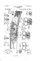
- Fig. 5 is a section taken w transversely through the barrels and through the lock, practically on the line 55 of Fig. 3, looking in direction of the frontof the firearm.
- Fig. 6 is a similar View looking in direction of the rear.
- Fig. 7 is a detail side elevation of one of the ejecting levers.
- Fig. 8 is a rear elevation of a pair of such levers.
- Fig. 1 is a longitudinal section taken through the lock and a portion of the barrel of what is known as the Parker gun.
- Fig. 2 is a bottom plan View of the lock, thelower casing plate having been removed.
- Fig. 9 is a side elevation of one of the cooking links or hooks.
- Fig. 10 is a front elevation partly in section of a set of such hooks-or links, and
- Fig. 11 is a vertical section taken practically on the line 11ll of Fig. 10,illustrating the interior construction of the cooking link or hook.
- Fig. 12 a plan View of a set of cooking tumblers.
- Fig. 13 is a side elevation of one of said tumblers.
- Fig. 1% is a rear elevation of a set of the tumblers, illustrating their connection with the cooking slide; and
- Fig. 15 is a detail view of an ejecting lever and attached cocking link or hook, illustrating a slight modification in the formation of the lever.
- Fig. 16 is a longitudinal section partly in the plane of the spring and partly in the plane of cooking and ejecting mechanism; the position of said parts being as they ap pear when about to eject the shell.
- the look A of the gun is secured to the stock 13 in any approved manner; and the barrels G, are hinged upon the outer forward end of the lock preferably in such manner that they may be readily disconnected from the lock; and the hinged connection is so made as to enable the breech of the barrels to be carried upward above the look, as best shown in Fig. 1.
- the usual trigger guard 10, is provided, and triggers 11, the inner ends 12 of the triggers being provided with recesses 13, to receive one end of the sears 1a, the latter being those employed in the Parker gun.
- sears at their inner ends are adapted to en- 7 gage with and hold the hammers 15 ina position to admit of firing charges from the barrels; and to that end each of the hammers at its lower edge upon its under face is provided with two shoulders 16 and 17, the shoulder 16 in each hammer being adapted to be en gaged by the sear 14 opposite it. It will be understood that there are two hammers when two barrels are employed, and that they are located at the sides of the lock, and forward of its fulcrum point each hammer has pivotally attached thereto a link 18 as is best shown in Fig. 16.
- Theselinks are each adapted to engage with and enter springs 19, preferably of the coil or spiral pattern, which springs are located within chambers formed in opposite side portions of the look, as shown in both Figs. and 6, the tension of the springs being to normally force the hammers upward to and contact with shells when the latter are placed in the barrels.
- ejector D This ejector, which is made in two sections (:1 and d, is shown best in Fig. 4, the sections being adapted to slide one upon the other, one section being purposed to engage with and remove the shell or shells contained in one barrel, while the other section performs similar offices for the shell or shells in the other barrel.
- Each ejector consists primarily of a body rod 20, and these rods are held to slide upon each other, together or independently, in a longitudinal chamber 21, produced in the metal between the barrels of the gun at the breech thereof, the opening or chamber extending through the breech.
- Each body bar 20 carries at its outer end a semi-circular extension 22, located at right angles to the body, the said extension being of skeleton form and of such shape as to enable it to clamp a shell at its outer or closed end, and each arm of each body of the ejector is provided with a guide pin 23, extending inwardly and forwardly within a suit-able chamber in which the pins have free movement.
- recesses 24 are produced, the end walls of these recesses being preferably diagonally shaped, and the recesses are merged one into the other, that is, a recess in one body bar is in direct communication with that of the other and the recesses are located ordinarily about centrally of the body bar.
- ejecting levers In connection with the body bars of the ejector two ejectinglevers 25, are employed. These ejecting levers are essentially L-shaped or angular in general contour, the horizontal section being the inner section and the vertical section the outer one; and these sections or members are designated as 25 and 25".
- the levers 25, are pivotally connected at the forward ends of their horizontal sections, as shown at 26 in Figs. 1 and 3, the pivotal attachment of thelevers being made preferably to side ears 27, which extend downward from the under face of the barrels, as shown in Fig. 5.
- the vertical members or sections 25 of the ejecting levers extend upward through the recesses 24 in the ejector body bars and the upper ends of the vertical members of the ejector levers terminate in heads 28, as
- each lever 25 has pivotally connected with its rear lower portion a cooking hook or link E.
- the cooking link or hook is shown in detail in Figs. 9, l0 and 11, and each is identical in construction.
- the outer faces of each of the links or hooks are flat, while extensions 31, are made upon their inner or opposing sides, as shown in Fig.
- hooks or links are provided with openings 33, adapted for pins or pivots 34., to be passed through them into the outer sides of the ejector levers; or the pins may be carried by the levers.
- Each link is practically made of hook form at its lower portion, and this is accomplished by forming in the rear edge of each a diagonal recess 35, the diagonal recesses entering into the longitudinal openings or recesses 32, and they extend practically to the base wall of these longitudinal openings between the top and bottom thereof, as best shown in Fig. 9, the hooked contour of these portions being shown in Figs. 9 and 11.
- each ejecting lever is provided with a hook or link E, so each hook or link is provided with a cooking tumbler F.
- the cocking tumblers are somewhat angular or L- shaped in cross section, as may be readily seen from the side View of one of them illustrated in Fig. 13.
- One member 36 of each tumbler is wider than the other member 37; and the member 37, which is the lower one,is usually made to terminate at its lower end in somewhat of a spherical shape, as shown at 38 in said Fig. 13.
- the inner face of the member 36 of each tumbler is provided with a marginal flange 39, which extends beyond the body portion 40 thereof, as shown in Figs.
- a tapering tongue 41 is projected parallel with the flange 39, this tongue terminating at its lower or reduced end preferablyin a spherical shape, as shown in dotted lines in Fig. 13, and in positive lines in Fig. 12. This is done in order that the lower end of the tongue as well as the lower end of the lower member 37, may be adapted as a bearing.
- the two cocking tumblers are pivoted side by side within the lock between the side walls thereof by means of a pin 42, or like device, capable of being removed; and the tongue 41 of each of the tumblers enters a recess 35 in each of the links or hooks.
- a looking yet pivotal engagement is effected between the tumblers and their forwardly opposing hooks or links.
- the tumblers, the links and the ejector levers are adapted to co-act with the hammers simultaneously and while ejecting shells, while shortly after the ejectment occurs the said parts act to lock the hammers in firing position.
- the connecting medium comprises two cocking slides H, having movement upon the base of the lock, as shown in Figs. 1, 2, and 3. These slides are also somewhat angular or L-shaped in general contour, as is more plainly shown in Fig. 2, the branch memberbeing at their rear ends. The longer member is designated as 43 and the branch member as 44.
- the long members 43 move parallel and virtually in contact, their opposing faces being straight and smooth, while the shorter members 44, project upward, or essentially at a right angle from the longer members and serve as lugs, the lugs being adapted for engagement with the shoulder of the hammers; while at the forward end of each of the cocking slides a socket 45, is produced,aud into and practically through these sockets the spherical lower ends of the cocking tumblers extend.
- the hooks or links E are held constantly in engagement with the cooking tumblers by means of springs 46, which springs are usually carried by the levers 25, and bear against the forward edges of the links or hooks.
- springs may be of any approved or desired construction, two means of locating the springs being shown in the drawings. That method shown in Fig. 1, consists in attaching to the under faces of the levers 25 one end of the springs, the opposite end of said springs extending downward to abearing against the links, while in Fig. 15, the spring is a spiral one, and is held to slide in a socket in an extension of the under face of the horizontal members of the levers, and this spring controls a bolt which has bearing against the links.
- neither of the ejectors will expel an empty shell from the gun barrels while the hammers arein their cocked position, as at that time their springs 19, are contracted and have no bearing whatever upon the ejecting mechanism,with the slides, tumblers, hooks or links and ejecting levers; and when the hammers are in their cocked positions they are so held by the sears 14, until the triggers connected with the hammers by the sears are operated to fire ,a charge.
- the shell may be rapidly, conveniently and efficieutly ejected from its barrel in the following manner: After the charge has been fired the shoulder 17 of the hammer tripped will occupy a position in contact with the forward face of thelug 44 of the cocking slide.
- the latch G that may be used to lock the barrel to the stock is manipulated to release the barrel, and the breech end of the barrel is carried upward.
- the limit of the outward movement given to the ejector section engaging with a loaded shell will be a distance only equal to the throw imparted to the ejector section by the finger 29, as the hammer belonging to that barrel isin its cocked position, and therefore the spring belonging to the hammer exerts no tension whatever upon the ejecting mechanism; on the other hand, the hammer of the other barrel being in the position it maintains after firing, that is in an upright position, its spring will be expaned and will exert rearward tension upon the ejecting mechanism connected with the hammer upon which the spring has bearing.
- a fire arm the combination, with the barrels thereof, and an ejector constructed in two independent sections,one having sliding movement in connection with each barrel, of a lock comprising two springcontrolled hammers, one for each barrel, triggeroperated sears adapted as looks for the hammers, cockingslides having bearing at one of their sides against the hammers, and cocking tumblers fulcrumed upon a fixed support within the lock casing, one end of said tum blers engaging with the cooking slides, each set of hammers, cocking slides and cooking tumblers being independent, ejecting levers fulcrumed one beneath each barrel, which levers pass through and act upon the ejector sections, and links pivotally connected with the levers, said links having pivotal and looking engagement with the cooking tumblers, as and for the purpose specified.
Landscapes
- Engineering & Computer Science (AREA)
- General Engineering & Computer Science (AREA)
- Toys (AREA)
Description
(No Model.) 3 SheetsSheet 1.
' G. H. GARRISO N.
FIREARM.
o. 509,727. Patentd Nov. 28, 1.893.
WITNESSES: Woa g?! y W .6. v ATTOHNEYQ.
(No Model.)
3 Sheets-Sheep 3. G. H. GARRISON.
FIREARM.
No. 509,727., Patented Nov. 28, 1893.
INVENTOH ATTORNEYS.
UNTTED STATES PATENT @FFEQE.
GEORGE H. GARRISON, OF SUMAS CITY, \VASHINGTON.
FIREARM.
SPECIFICATION forming part of Letters Patent No. 509,727, dated November 28, 1893. Application filed July 9, 1892. SarialNo- 439.458- (No model.)
To all whom it may concern.-
Be it known that I, GEORGE H. GARRISON, of Sum-a City, in the countyofWhatcom and State of \Vashington, have invented a new and useful Improvement in Firearms, of which the following is a full, clear, and exact description.
My invention relates to an improvement in fire arms, and has for its object especially to improve the construction of double-barreled guns of the breech-loading pattern, to such an extent as to provide for the automatic extraction or ejection of the cartridge shells and the simultaneous and automatic cooking of the hammers when the barrels are brought in position for the shell or shells to be ejected.
It is another object of the invention to so construct the fire arm that even when both barrels are loaded the shells will be ejected therefrom only when empty, even when the gun barrels are brought in position to otherwise accomplish the ejectment. In other words, unless the hammer has been carried to its firing position the shell with which that hammer is to be brought in contact will not be ejected.
It is another object of the invention to provide an ejector especially adapted for use in connection with what is known commercially as the Parker gun, and to provide an attachment whereby the empty shells may be ejected from one or from both barrels, as occasion may demand, which attachment will be not only simple, but will be positive, durable and effective in its action and comprising but few parts which do not tend in the least to complicate the ordinary working portions of said gun.
The invention consists in the novel construction and combination of the several parts, as will be hereinafterfully set forth and pointed out in the claims.
Reference is to be had to the accompanying drawings forming apart of this specification, in which similar figures and letters of reference indicate corresponding parts in all the views.
Figure 1 is a longitudinal section taken through the lock and a portion of the barrel of what is known as the Parker gun. Fig. 2 is a bottom plan View of the lock, thelower casing plate having been removed. Fig. 3 is a View practically the same as Fig. 1, the barrel being in this view shown as in position end view the ejector. Fig. 5 is a section taken w transversely through the barrels and through the lock, practically on the line 55 of Fig. 3, looking in direction of the frontof the firearm. Fig. 6 is a similar View looking in direction of the rear. Fig. 7 is a detail side elevation of one of the ejecting levers. Fig. 8 is a rear elevation of a pair of such levers. Fig. 9 isa side elevation of one of the cooking links or hooks. Fig. 10 is a front elevation partly in section of a set of such hooks-or links, and Fig. 11 is a vertical section taken practically on the line 11ll of Fig. 10,illustrating the interior construction of the cooking link or hook. Fig. 12 a plan View of a set of cooking tumblers. Fig. 13 is a side elevation of one of said tumblers. Fig. 1% is a rear elevation of a set of the tumblers, illustrating their connection with the cooking slide; and Fig. 15 is a detail view of an ejecting lever and attached cocking link or hook, illustrating a slight modification in the formation of the lever. Fig. 16 is a longitudinal section partly in the plane of the spring and partly in the plane of cooking and ejecting mechanism; the position of said parts being as they ap pear when about to eject the shell.
The look A of the gun is secured to the stock 13 in any approved manner; and the barrels G, are hinged upon the outer forward end of the lock preferably in such manner that they may be readily disconnected from the lock; and the hinged connection is so made as to enable the breech of the barrels to be carried upward above the look, as best shown in Fig. 1. The usual trigger guard 10, is provided, and triggers 11, the inner ends 12 of the triggers being provided with recesses 13, to receive one end of the sears 1a, the latter being those employed in the Parker gun. The
sears at their inner ends are adapted to en- 7 gage with and hold the hammers 15 ina position to admit of firing charges from the barrels; and to that end each of the hammers at its lower edge upon its under face is provided with two shoulders 16 and 17, the shoulder 16 in each hammer being adapted to be en gaged by the sear 14 opposite it. It will be understood that there are two hammers when two barrels are employed, and that they are located at the sides of the lock, and forward of its fulcrum point each hammer has pivotally attached thereto a link 18 as is best shown in Fig. 16. Theselinks are each adapted to engage with and enter springs 19, preferably of the coil or spiral pattern, which springs are located within chambers formed in opposite side portions of the look, as shown in both Figs. and 6, the tension of the springs being to normally force the hammers upward to and contact with shells when the latter are placed in the barrels.
Before proceeding further with the description of the interior mechanism of the lock 1 will describe the ejector D. This ejector, which is made in two sections (:1 and d, is shown best in Fig. 4, the sections being adapted to slide one upon the other, one section being purposed to engage with and remove the shell or shells contained in one barrel, while the other section performs similar offices for the shell or shells in the other barrel. Each ejector consists primarily of a body rod 20, and these rods are held to slide upon each other, together or independently, in a longitudinal chamber 21, produced in the metal between the barrels of the gun at the breech thereof, the opening or chamber extending through the breech. Each body bar 20, carries at its outer end a semi-circular extension 22, located at right angles to the body, the said extension being of skeleton form and of such shape as to enable it to clamp a shell at its outer or closed end, and each arm of each body of the ejector is provided with a guide pin 23, extending inwardly and forwardly within a suit-able chamber in which the pins have free movement. In the opposing surface of the two body portions of the ejector, recesses 24: are produced, the end walls of these recesses being preferably diagonally shaped, and the recesses are merged one into the other, that is, a recess in one body bar is in direct communication with that of the other and the recesses are located ordinarily about centrally of the body bar. In connection with the body bars of the ejector two ejectinglevers 25, are employed. These ejecting levers are essentially L-shaped or angular in general contour, the horizontal section being the inner section and the vertical section the outer one; and these sections or members are designated as 25 and 25". The levers 25, are pivotally connected at the forward ends of their horizontal sections, as shown at 26 in Figs. 1 and 3, the pivotal attachment of thelevers being made preferably to side ears 27, which extend downward from the under face of the barrels, as shown in Fig. 5. The vertical members or sections 25 of the ejecting levers extend upward through the recesses 24 in the ejector body bars and the upper ends of the vertical members of the ejector levers terminate in heads 28, as
best shown in Fig. 3. When the hammers of the barrel of the gun are brought to the cocking position, the heads 28 of the ejector levers will rest upon the opposed faces of the body bars 20 of the ejectors, and the rear edges of the levers will be practically in engagement with the rear inclined walls m of the recesses 24 of the ejectors, as shown in Fig. 3, and some space will be left between the forward edges of the levers and the forward end walls of the recesses 24, which latter walls are also inclined. At the hinged connection of the barrels with the stock a finger 29, is located. While the hammers are being brought to a cooked position by opening the gun, the fin= ger 29 will force outward the ejector lever bars 20, and the bottom surface of the ejector lever heads 28, sliding on the upper surfaces of the bars 20 will, when the barrels have opened enough to allow the empty shells to be drawn from the gun, become disengaged, or will reach the end of the upper surface of the rods 20 and will fall into the recesses 2%. At this moment the hammers will have been raised far enough for the sears 1a to engage the shoulders 16. See Fig. 3.. Thus the force of the main spring will be communicated through the medium of the pieces 18, 15, H, F and E, to the ejector levers 25, and will draw said levers downward into the position shown in Fig. 1, and it will be observed that in so doing the inclined faces of the ejector levers 25, sliding down the forward inclined wall of the recesess 24, cause the levers to rapidly move outward and eject the shells. After the ejector levers reach the position shown in Fig. 1, the barrels of the gun continuing to move to an open position, will bring the hammers up sufficiently for the scars 1A to engage the hammer shoulders 16. Each lever 25, has pivotally connected with its rear lower portion a cooking hook or link E. The cooking link or hook is shown in detail in Figs. 9, l0 and 11, and each is identical in construction. The outer faces of each of the links or hooks are flat, while extensions 31, are made upon their inner or opposing sides, as shown in Fig. 10, while partially in the extensions of the hooks and partially in their body portions, longidinal recesses or openings 32, are produced, extending from a point near their lower ends and terminating a slight distance from their upper ends. The upper ends of the hooks or links are provided with openings 33, adapted for pins or pivots 34., to be passed through them into the outer sides of the ejector levers; or the pins may be carried by the levers. Each link is practically made of hook form at its lower portion, and this is accomplished by forming in the rear edge of each a diagonal recess 35, the diagonal recesses entering into the longitudinal openings or recesses 32, and they extend practically to the base wall of these longitudinal openings between the top and bottom thereof, as best shown in Fig. 9, the hooked contour of these portions being shown in Figs. 9 and 11.
As each ejecting lever is provided with a hook or link E, so each hook or link is provided with a cooking tumbler F. The cocking tumblers are somewhat angular or L- shaped in cross section, as may be readily seen from the side View of one of them illustrated in Fig. 13. One member 36 of each tumbler is wider than the other member 37; and the member 37, which is the lower one,is usually made to terminate at its lower end in somewhat of a spherical shape, as shown at 38 in said Fig. 13. The inner face of the member 36 of each tumbler is provided with a marginal flange 39, which extends beyond the body portion 40 thereof, as shown in Figs. 3 and 12; and from the forward edge of the body portion of the member 36 of each tumbler a tapering tongue 41, is projected parallel with the flange 39, this tongue terminating at its lower or reduced end preferablyin a spherical shape, as shown in dotted lines in Fig. 13, and in positive lines in Fig. 12. This is done in order that the lower end of the tongue as well as the lower end of the lower member 37, may be adapted as a bearing.
The two cocking tumblers are pivoted side by side within the lock between the side walls thereof by means of a pin 42, or like device, capable of being removed; and the tongue 41 of each of the tumblers enters a recess 35 in each of the links or hooks. Thus a looking yet pivotal engagement is effected between the tumblers and their forwardly opposing hooks or links.
The tumblers, the links and the ejector levers are adapted to co-act with the hammers simultaneously and while ejecting shells, while shortly after the ejectment occurs the said parts act to lock the hammers in firing position. The connecting medium comprises two cocking slides H, having movement upon the base of the lock, as shown in Figs. 1, 2, and 3. These slides are also somewhat angular or L-shaped in general contour, as is more plainly shown in Fig. 2, the branch memberbeing at their rear ends. The longer member is designated as 43 and the branch member as 44. The long members 43 move parallel and virtually in contact, their opposing faces being straight and smooth, while the shorter members 44, project upward, or essentially at a right angle from the longer members and serve as lugs, the lugs being adapted for engagement with the shoulder of the hammers; while at the forward end of each of the cocking slides a socket 45, is produced,aud into and practically through these sockets the spherical lower ends of the cocking tumblers extend.
The hooks or links E, are held constantly in engagement with the cooking tumblers by means of springs 46, which springs are usually carried by the levers 25, and bear against the forward edges of the links or hooks.
These springs may be of any approved or desired construction, two means of locating the springs being shown in the drawings. That method shown in Fig. 1, consists in attaching to the under faces of the levers 25 one end of the springs, the opposite end of said springs extending downward to abearing against the links, while in Fig. 15, the spring is a spiral one, and is held to slide in a socket in an extension of the under face of the horizontal members of the levers, and this spring controls a bolt which has bearing against the links.
It will be observed that there is a separate ejector, ejector lever, link or hook, cocking tumbler and slide for each barrel as well as a separate hammer; and the two sets of parts above mentioned may be made to act together, or each set may be operated independently.
At this point it maybe well to mention that neither of the ejectors will expel an empty shell from the gun barrels while the hammers arein their cocked position, as at that time their springs 19, are contracted and have no bearing whatever upon the ejecting mechanism,with the slides, tumblers, hooks or links and ejecting levers; and when the hammers are in their cocked positions they are so held by the sears 14, until the triggers connected with the hammers by the sears are operated to fire ,a charge. Supposing each of the barrels to be loaded with a charged shell, and taking it for granted that one of the triggers has been drawn to cause a hammer to impinge upon the shell and explode its charge, the shell may be rapidly, conveniently and efficieutly ejected from its barrel in the following manner: After the charge has been fired the shoulder 17 of the hammer tripped will occupy a position in contact with the forward face of thelug 44 of the cocking slide. The latch G that may be used to lock the barrel to the stock is manipulated to release the barrel, and the breech end of the barrel is carried upward. As it is carried upward the finger 29, at the hinged connection of the barrel with the lock, will press both of the body portions of the ejectors so far forward as to carry their arms 22 away from the breech and carry the shells out a sufficient distance to be readily grasped, but the empty shell will be violently thrown from its barrel, and this is accomplished when the barrels have reached the position substantially shown in Fig. 1.
Before proceeding farther with the description of the direct propelling of the shell, it may be well to remark that as the barrels are tilted upward at their breeches the heads of the levers 25, will also be carried up, and the links or hooks and tumblers will be so rocked as to move both of the cocking slides forward. As the levers rock they move downward and forward along the bodies 20 of the ejector sections. The limit of the outward movement given to the ejector section engaging with a loaded shell will be a distance only equal to the throw imparted to the ejector section by the finger 29, as the hammer belonging to that barrel isin its cocked position, and therefore the spring belonging to the hammer exerts no tension whatever upon the ejecting mechanism; on the other hand, the hammer of the other barrel being in the position it maintains after firing, that is in an upright position, its spring will be expaned and will exert rearward tension upon the ejecting mechanism connected with the hammer upon which the spring has bearing. Therefore, the moment that the breech of the barrels is elevated a sufficient distance to bring the head of the lever 25 operating in conjunction with the ejector section of the fired barrel, the rear tension of the spring upon the ejecting mechanism will quickly draw downward the lever and cause its head to engage with the rear inclined Wall of the slot 2a in the ejector section. As this action is very quick and somewhat powerful, the ejector section acted upon is thrown outward with great force, and consequently the shell is quickly thrown from the barrel, even some distance therefrom. After the shell has been ejected, by carrying the barrel slightly farther upward, the cocking of the hammer will be consummated, as while the lever 25, was acting the cooking slide H, connected with it, was drawn forward, and it engaging with the shoulder 17 of the hammer acted to draw the hammer down to such a position that it could be caught and locked in the firing position by its sear com ing in engagement with the shoulder 16, as shown in both Figs. 1 and 2. When another shell is introduced into the barrel that has been fired the barrels are restored to their normal position, and the heads of the levers 25, in enteringthe slots 24 of the ejector, are restored to their normal position. It will thus be observed that unless the charge from the shell has been fired it cannot be ejected from the barrels when the latter are opened out from the stock. It is further evident that there are no springs controlling the movement of the parts except the springs usually employed and termed the main springs for the control of the hammers. This spring is made to act with all of its strength to assist in the ejectment of the shells.
Attention is once more called to the fact that the ejectment of the shells from either barrel may be carried on independently; or if the charges from both barrels have been fired the ejectment of both shells may be simultaneously accomplished.
Having thus described my invention, I claim as new and desire to secure by Letters Patent- 1. In a fire arm, the combination, with an ejector, a spring-controlled hammer, and a cooking slide operating upon the hammer, of an ejector lever, the upper end whereof has bearing against the ejector, a link or hook pivotally connected with the ejector lever, and a cooking tumbler fulcrumed upon a fixed support and pivotally connected with the cocking slide, the cooking link and tumbler, as and for the purpose specified.
2. In a fire arm, the combination, with the barrels thereof, and an ejector constructed in two independent sections,one having sliding movement in connection with each barrel, of a lock comprising two springcontrolled hammers, one for each barrel, triggeroperated sears adapted as looks for the hammers, cockingslides having bearing at one of their sides against the hammers, and cocking tumblers fulcrumed upon a fixed support within the lock casing, one end of said tum blers engaging with the cooking slides, each set of hammers, cocking slides and cooking tumblers being independent, ejecting levers fulcrumed one beneath each barrel, which levers pass through and act upon the ejector sections, and links pivotally connected with the levers, said links having pivotal and looking engagement with the cooking tumblers, as and for the purpose specified.
3. In a fire arm, the combination, with the cooking mechanism, of an ejector adapted for sliding movement upon a barrel, the said ejector being provided with an opening extending through it, one wallwhereof is diagonal, an ejecting lever fulcrumed beneath the ejector and 'of angular construction, one member extending upward through the slot in the ejector and terminating in a head, and a link or hook pivotally connected with the lever at one side of its fulcrum and also pivotally connected with the cooking mechanism of the gun, as and for the purpose specified.
4. In a double-barreled gun, the combination, with the cooking mechanism, the said cocking mechanism being independent in its action for each barrel, of cooking tumblers having pivotal connection with the cocking mechanism, the said tumblers being independent, an ejector constructed in sections each section being held to slide beneath a. barrel independently and provided with an opening in its body, one wall of which is inclined, an angled lever fulcru med beneath each ejector section near one end of its horizontal member, the vertical members of the levers passing upward through the openings in the ejector sections, the upper ends of said members being formed with inclined planes, and cooking links or hooks pivotally carried by the levers, the said hooks or links being in pivot-a1 and locking engagement with the cooking tumblers, as and for the purpose specified.
GEORGE H. GARRISON.
W'itnesses:
J. FRED ACKER, C. SEDGVVIOK.
ICC
Publications (1)
| Publication Number | Publication Date |
|---|---|
| US509727A true US509727A (en) | 1893-11-28 |
Family
ID=2578555
Family Applications (1)
| Application Number | Title | Priority Date | Filing Date |
|---|---|---|---|
| US509727D Expired - Lifetime US509727A (en) | Firearm |
Country Status (1)
| Country | Link |
|---|---|
| US (1) | US509727A (en) |
-
0
- US US509727D patent/US509727A/en not_active Expired - Lifetime
Similar Documents
| Publication | Publication Date | Title |
|---|---|---|
| US870719A (en) | Automatic firearm. | |
| US394844A (en) | Mingham | |
| US509727A (en) | Firearm | |
| US261648A (en) | Breech-loading fire-arm | |
| US566367A (en) | Magazine-pistol | |
| US528508A (en) | Ejector for breakdown guns | |
| US214098A (en) | Improvement in breech-loading fire-arms | |
| US490065A (en) | Breech-loading firearm | |
| US743002A (en) | Rapid-fire pistol. | |
| US79291A (en) | William morgenstern | |
| US853073A (en) | Breech-loading small-arms. | |
| US791411A (en) | Magazine-firearm. | |
| US116068A (en) | Improvement in breech-loading fire-arms | |
| USRE5433E (en) | Improvement in breech-loading fire-arms | |
| US562286A (en) | deng-o | |
| US120788A (en) | William s | |
| US493084A (en) | Breech-loading shotgun | |
| US137625A (en) | Improvement in breech-loading fire-arms | |
| US535528A (en) | Ejecting mechanism for breakdown guns | |
| US441395A (en) | Breech loading gun | |
| US354452A (en) | walker | |
| US150201A (en) | Improvement in breech-loading fire-arms | |
| US180803A (en) | Improvement in breech-loading fire-arms | |
| US51213A (en) | Improvx | |
| US307626A (en) | brewer |