US5092292A - Lubricating apparatus of motorcycle engine - Google Patents
Lubricating apparatus of motorcycle engine Download PDFInfo
- Publication number
- US5092292A US5092292A US07/472,929 US47292990A US5092292A US 5092292 A US5092292 A US 5092292A US 47292990 A US47292990 A US 47292990A US 5092292 A US5092292 A US 5092292A
- Authority
- US
- United States
- Prior art keywords
- oil passage
- crank case
- oil
- cam
- side wall
- Prior art date
- Legal status (The legal status is an assumption and is not a legal conclusion. Google has not performed a legal analysis and makes no representation as to the accuracy of the status listed.)
- Expired - Lifetime
Links
Images


Classifications
-
- F—MECHANICAL ENGINEERING; LIGHTING; HEATING; WEAPONS; BLASTING
- F01—MACHINES OR ENGINES IN GENERAL; ENGINE PLANTS IN GENERAL; STEAM ENGINES
- F01P—COOLING OF MACHINES OR ENGINES IN GENERAL; COOLING OF INTERNAL-COMBUSTION ENGINES
- F01P3/00—Liquid cooling
- F01P3/06—Arrangements for cooling pistons
- F01P3/08—Cooling of piston exterior only, e.g. by jets
-
- F—MECHANICAL ENGINEERING; LIGHTING; HEATING; WEAPONS; BLASTING
- F01—MACHINES OR ENGINES IN GENERAL; ENGINE PLANTS IN GENERAL; STEAM ENGINES
- F01M—LUBRICATING OF MACHINES OR ENGINES IN GENERAL; LUBRICATING INTERNAL COMBUSTION ENGINES; CRANKCASE VENTILATING
- F01M1/00—Pressure lubrication
- F01M1/08—Lubricating systems characterised by the provision therein of lubricant jetting means
-
- F—MECHANICAL ENGINEERING; LIGHTING; HEATING; WEAPONS; BLASTING
- F02—COMBUSTION ENGINES; HOT-GAS OR COMBUSTION-PRODUCT ENGINE PLANTS
- F02B—INTERNAL-COMBUSTION PISTON ENGINES; COMBUSTION ENGINES IN GENERAL
- F02B75/00—Other engines
- F02B75/16—Engines characterised by number of cylinders, e.g. single-cylinder engines
-
- F—MECHANICAL ENGINEERING; LIGHTING; HEATING; WEAPONS; BLASTING
- F02—COMBUSTION ENGINES; HOT-GAS OR COMBUSTION-PRODUCT ENGINE PLANTS
- F02B—INTERNAL-COMBUSTION PISTON ENGINES; COMBUSTION ENGINES IN GENERAL
- F02B75/00—Other engines
- F02B75/02—Engines characterised by their cycles, e.g. six-stroke
- F02B2075/022—Engines characterised by their cycles, e.g. six-stroke having less than six strokes per cycle
- F02B2075/027—Engines characterised by their cycles, e.g. six-stroke having less than six strokes per cycle four
-
- F—MECHANICAL ENGINEERING; LIGHTING; HEATING; WEAPONS; BLASTING
- F02—COMBUSTION ENGINES; HOT-GAS OR COMBUSTION-PRODUCT ENGINE PLANTS
- F02B—INTERNAL-COMBUSTION PISTON ENGINES; COMBUSTION ENGINES IN GENERAL
- F02B2275/00—Other engines, components or details, not provided for in other groups of this subclass
- F02B2275/20—SOHC [Single overhead camshaft]
-
- F—MECHANICAL ENGINEERING; LIGHTING; HEATING; WEAPONS; BLASTING
- F02—COMBUSTION ENGINES; HOT-GAS OR COMBUSTION-PRODUCT ENGINE PLANTS
- F02B—INTERNAL-COMBUSTION PISTON ENGINES; COMBUSTION ENGINES IN GENERAL
- F02B61/00—Adaptations of engines for driving vehicles or for driving propellers; Combinations of engines with gearing
- F02B61/02—Adaptations of engines for driving vehicles or for driving propellers; Combinations of engines with gearing for driving cycles
Definitions
- This invention relates to lubricating apparatus for a motorcycle engine, and more particularly to lubricating apparatus for cooling a piston of an overhead cam type four-cycle engine.
- a four-cycle engine mounted upon a motorcycle is usually of the overhead cam type and is provided with a cam chamber within which a cam chain for driving the cam is accommodated and which is usually integrally formed within and with a cylinder block and a cylinder head.
- Lubrication for a variable valve mechanism, a large diametered portion of a control rod of the engine cylinder, a bearing portion of the crank shaft, and the like of the engine of the type described above is performed by means of lubricating oil pumped from an oil pan disposed within a lower bottom portion of a crank case by means of an oil pump through an oil passage formed so as to penetrate a thickened portion of the crank case and an oil passage composed of a recessed groove formed within a mating face of the crank case to be mated with a side cover.
- Lubrication inclusive of the cooling of the piston is further performed for achieving the lubrication between the cylinder and the piston and between a small diametered portion of the control rod and a piston pin by properly supplying oil to the lower surface of the piston by suitable oil jetting means.
- the oil jetting means is, in one arrangement, disposed directly below the lower end of the piston when the same is positioned at a lower dead position and is embedded within the upper end portion of the side wall of the crank case so that the front end of the jetting means is directed toward the inner surface of the piston through means of a gap defined between the lower end opening of the cylinder and the outer peripheral side surface of the crank web.
- the oil is supplied to an oil passage formed so as to penetrate a thickened portion of the side wall of the crank case.
- the oil jetting means is itself disposed at the same position as described with respect to the above arrangement, but in this arrangement, the oil is supplied to the jetting means through means of an oil passage formed within the outer periphery of a bearing of the crank shaft.
- an oil connection passage is provided for the oil jetting means so as to thereby simplify the entire structure.
- An object of the invention is to substantially eliminate the defects or drawbacks encountered with the conventional technology described above and to provide a lubricating apparatus for a motorcycle engine which is particularly provided with a cam chain chamber and which is capable of supplying oil to the lower surface of the piston of the engine unit which is located at a lower dead position without forming a complicated oil passage means, thus improving the workability of the lubricating apparatus with reduced manufacturing costs.
- a lubricating apparatus for a motorcycle engine in which there is arranged a crank case within which is mounted a crank shaft having one end extending outwardly from a side wall of the crank case, the extending one end being covered by means of a side cover, a cam sprocket drive gear is mounted upon the crank shaft, and a cam chain chamber within which a chain is disposed in the form of a loop between the cam drive sprocket gear and a cam driven sprocket gear is formed upon one side of a cylinder block including a cylinder and a piston and a cylinder head disposed above the cam sprocket drive gear, and characterized within that a passage hole is formed in a mating face of the crank case to be mated with the side cover and an oil passage tube is inserted into the passage hole, the oil passage tube having a front end provided with at least one oil jetting hole extending through an inner space defined by means of the looped cam chain and
- the oil passage tube is provided with a rear end having a portion bent outwardly normal to the longitudinal axis of the oil passage tube and the mating face of the crank case is provided with an engaging groove which is engaged by the bent portion of the oil passage tube.
- the oil can be directly supplied towards the lower surface of the piston when the same is disposed at the lower dead position by discharging the oil through means of the jetting hole formed within the front end of the oil passage tube inserted within the engine unit through the side wall of the crank case from the oil passage formed within the mating faces defined between the crank case and the side cover.
- This structure can eliminate the location of the oil passage at the lower portion of the crank case or within the thickened portion of the side wall of the crank case.
- the oil passage tube can be inserted into a hole formed normal to the mating face at a time of performing the necessary drilling operations for the screw holes workability of the lubrication apparatus, that is, the engine unit.
- the oil passage tube can be easily removed simply by removing the side cover, resulting in high maintenance performance characteristics.
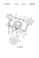
- FIG. 1 is an elevational section of a single cylinder four-cycle engine of a motorcycle
- FIG. 2 is an elevational section taken along the line 2--2 shown in FIG. 1;
- FIG. 3 is an enlarged sectional view showing mating portions of the crank case and the side cover of the engine shown in FIG. 1;
- FIG. 4 is an enlarged sectional view taken normal to the sectional view shown in FIG. 3 and within a plane including the oil jetting holes of the oil passage tube;
- FIG. 5 is a front view of the oil passage tube on an enlarged scale shown in FIG. 1;
- FIGS. 6, 7 and 8 are sectional views taken along the lines 6--6, 7--7 and 8--8 shown in FIG. 5;
- FIGS. 9 and 10 are partial elevational sections of conventional piston cooling devices for a motorcycle engine.
- FIG. 9 is an elevational section of a conventional piston cooling device of an engine unit of a motorcycle, and an oil jetting means of this piston cooling device is disposed directly below the lower end of the piston 101 which is illustrated as being disposed at a lower dead position and is embedded within the upper end portion of the side wall 104 of the crank case 103 so that the front end of the jetting means 105 is directed toward the inner surface of the piston through means of a gap defined between the lower end opening of the cylinder 100 and the outer peripheral side surface of a crank web 102.
- the oil is supplied to an oil passage 106 which is formed so as to penetrate the thickened portion of the side wall of the crank case.
- FIG. 10 shows another arrangement of a conventional piston cooling device, the oil jetting means 107 of this example being disposed at substantially the same position as that described with respect to the above arrangement of the jetting means 105 of FIG. 9, but in this arrangement, the oil is supplied to the jetting means 107 through means of an oil passage 109 formed within the outer peripheral of a bearing 108 of the crank shaft.
- the oil jetting means 105 and 107 are embedded within an oblique bore 110 or 111 formed within the upper end portion of the side wall of the crank case by means of the drilling operation, which must be done in an inclined manner. This involves troublesome working conditions and defects as described before.
- This invention was therefore conceived so as to substantially eliminate the defects or drawbacks encountered in connection with the prior art described above and will be described in detail hereunder with reference to FIGS. 1 to 8.
- FIG. 1 is an elevational front section of a single cylinder four-cycle engine provided with a lubrication apparatus according to this invention and FIG. 2 is a sectional view taken along the line 2--2 in FIG. 1.
- a piston 2 accommodated within a cylinder 1 is coupled with a crank 4 through means of a control rod 3 and is slidably displaced vertically in the illustrated arrangement in synchronism with the rotation of the crank 4.
- the crank 4 is supported upon side walls 7a and 7b of a crank case 6 by means of crank shafts 5a and 5b, which extend outwardly from the side walls 7a and 7b of the crank case 6, respectively.
- a cylinder head 9 is mounted upon a cylinder block 8 within which the cylinder 1 is formed, and the cylinder head 9 is provided with a combustion chamber 10 at the lower portion thereof to which an intake passage 11 and an exhaust passage 12 are connected so as to be opened or closed by means of the operations of an intake valve 13 and an exhaust valve 14.
- the opening and closing operations of both the valves 13 and 14 are controlled by means of the rotations of an intake cam 16 and an exhaust cam 17 journaled within the upper surface of the cylinder head 9 by means of the operations of rocker arms 18 and 19.
- the cam shaft 15 has one end upon which there is journaled a cam driven sprocket gear 20 which is driven through means of a cam chain 22 disposed in an annular loop between the cam driven sprocket gear 20 and a cam drive sprocket gear 21.
- the cam chain 22 is disposed within a cam chain chamber 23 formed within the cylinder block 8 and the cylinder head 9.
- a primary drive gear 24 is mounted upon the crank shaft 5b so as to be engageable with a primary driven gear 26 mounted upon a counter shaft 25.
- the counter shaft 25 is rotated through means of an open-close clutch 27 and the rotation of the counter shaft 25 is transmitted to a drive shaft 28 through means of a transmission gear mechanism, not shown.
- Reference numeral 29 designates a drive sprocket gear for the output mounted upon the drive shaft 28.
- crank shaft 5b, the cam drive sprocket gear 21, the primary drive gear 24, the primary driven gear 26, the open-close clutch 27, and the counter shaft 25 are substantially covered by means of the clutch cover 30 mounted upon one side of the crank case 6.
- a recessed groove 32 is formed within a mating face 31 of the clutch cover 30 to be mated with the crank case 6 and the groove 32 constitutes a passageway when the crank case 6 is mated with the clutch cover 30 so that oil fed from an oil pan disposed at the bottom portion of the crank case by means of the operation of an oil pump is guided within the recessed groove 32 formed as a part of the oil passage.
- the crank case 6 is also provided with a mating face 33 to be mated with the clutch cover 30 and, at the mating face 33, an oil passage tube 35 is inserted into a through hole 34 disposed parallel to the crank shaft 5b at a position above the cam drive sprocket gear 21.
- the oil passage tube 35 extends through the inner space of the annular loop arrangement of the cam chain 22 disposed within the vertical plane, as viewed, between the cam drive sprocket gear 21 and the cam driven sprocket gear 20 and further extends so as to penetrate the side wall 7b of the crank case so that the front end of the oil passage tube 35 extends outwardly into a gap 37 defined by means of the side surface of the outer peripheral portion of a crank web 36 disposed within a lower opened portion of the cylinder 1 directly below the lower edge of the piston 2 which is illustrated in the lower dead position.
- the oil passage tube 35 has a front end 35a at which one or more oil jetting holes 38 are formed and the rear end 35b of the tube 35 is open.
- the rear end 35b has a portion bent outwardly normal to the longitudinal axis of the tube 35 so as to serve as an engaging piece 39 to be engaged with the crank case 6.
- the engaging piece 39 is fitted within an engaging groove 40 formed within the mating face 33 of the crank case 6 so that the engaging piece 39, that is, the oil passage tube 35, is positioned and fixed with respect to any rotation thereof about the longitudinal axis thereof and the oil jetting hole 38 therefore always faces the lower surface of the piston 2 through means of the gap 37.
- the end face of the rear end 35b of the oil passage tube 35 is in registration with the mating face 33 so as to communicate with the recessed groove 32.
- the oil passage tube 35 is led to a position directly below the lower dead position of the piston 2 from the clutch cover 30 through the cam chain chamber 23 and the cooling oil can be supplied and jetted towards the lower surface of the piston 2 through means of the oil jetting hole 38. Accordingly, the location of an oil passage within the thickened portion of the side wall 7b of the crank case 6 can be eliminated, and the oil is fed to the upper portion of the side wall 7b of the crank case by way of an oil passage formed within the mating faces defined between the crank case 6 and the clutch cover 30, whereby the workability of the lubricating apparatus itself can be remarkably improved with reduced manufacturing cost. In addition, the oil passage tube can be easily removed from the lubricating apparatus by removing the clutch cover 30, thus easily performing any maintenance thereof.
- the arrangement of the oil passage tube may be arranged upon a side cover such as upon a magnet cover side except for the clutch cover side in the manner substantially identical to that described hereinbefore. It is therefore understood that within the scope of the appended claims, the present invention can be practiced otherwise than as specifically described herein.
Abstract
Description
Claims (9)
Applications Claiming Priority (4)
| Application Number | Priority Date | Filing Date | Title |
|---|---|---|---|
| JP1-21159 | 1989-01-31 | ||
| JP2115989A JP2629936B2 (en) | 1989-01-31 | 1989-01-31 | Motorcycle engine lubrication system |
| JP1-21160 | 1989-01-31 | ||
| JP2116089A JP2629937B2 (en) | 1989-01-31 | 1989-01-31 | Motorcycle engine lubrication system |
Publications (1)
| Publication Number | Publication Date |
|---|---|
| US5092292A true US5092292A (en) | 1992-03-03 |
Family
ID=26358189
Family Applications (1)
| Application Number | Title | Priority Date | Filing Date |
|---|---|---|---|
| US07/472,929 Expired - Lifetime US5092292A (en) | 1989-01-31 | 1990-01-31 | Lubricating apparatus of motorcycle engine |
Country Status (1)
| Country | Link |
|---|---|
| US (1) | US5092292A (en) |
Cited By (21)
| Publication number | Priority date | Publication date | Assignee | Title |
|---|---|---|---|---|
| US5857441A (en) * | 1996-10-29 | 1999-01-12 | Honda Giken Kogyo Kabushiki Kaisha | Valve mechanism lubricator of engine |
| US6047667A (en) * | 1998-07-24 | 2000-04-11 | Harley-Davidson Motor Company | Motorcycle camshaft support plate |
| US6205971B1 (en) * | 1998-09-12 | 2001-03-27 | Honda Giken Kogyo Kabushiki Kaisha | Crankshaft rotation structure for four cycle engine |
| US6332443B1 (en) * | 2000-08-29 | 2001-12-25 | Toyota Jidosha Kabushiki Kaisha | Lubricating oil supplying structure for crankshaft |
| US6412464B1 (en) * | 1999-11-12 | 2002-07-02 | Harley-Davidson Motor Company Group, Inc. | Chain guide for a control-shaft drive of an internal-combustion engine and method of producing a chain guide |
| US20040231626A1 (en) * | 2003-05-19 | 2004-11-25 | Trease John M. | Dual camshaft retaining plate |
| US6863042B2 (en) | 2002-09-27 | 2005-03-08 | Hyundai Motor Company | Lubrication system for the timing chains of an automotive V-type engine |
| EP1550795A1 (en) * | 2002-09-26 | 2005-07-06 | Honda Giken Kogyo Kabushiki Kaisha | Four-cycle, single-cylinder engine |
| US20050150725A1 (en) * | 2002-02-20 | 2005-07-14 | Yoji Utsumi | Lubrication device of engine |
| WO2005103456A3 (en) * | 2004-04-22 | 2006-03-23 | Wacker Construction Equipment | Oil supply for an internal combustion engine |
| EP1674687A1 (en) * | 2004-12-27 | 2006-06-28 | HONDA MOTOR CO., Ltd. | Piston cooling device |
| US20070000470A1 (en) * | 2005-07-01 | 2007-01-04 | Harley-Davidson Motor Company Group, Inc. | Oil pump for a motorcycle |
| US7171939B1 (en) | 2005-09-30 | 2007-02-06 | S&S Cycle, Inc. | Integrated cam drive and oil pump assembly for motorcycle engines and the like |
| US20070272196A1 (en) * | 2006-05-26 | 2007-11-29 | Honda Motor Co., Ltd. | Lubricating system for a vehicle power unit |
| US20090124441A1 (en) * | 2004-09-10 | 2009-05-14 | Schaeffler Kg | Housing of a tensioning system with an intergrated spray nozzle |
| US20100242893A1 (en) * | 2009-03-31 | 2010-09-30 | Honda Motor Co., Ltd. | Oil storage structure for engine, engine incorporating same, and vehicle incorporating same |
| US20110226200A1 (en) * | 2010-03-22 | 2011-09-22 | Trease John M | Axial float plate |
| US8678938B2 (en) | 2012-07-31 | 2014-03-25 | Harley-Davidson Motor Company Group, LLC | Lubricated engine compensator assembly and motorcycle having the same |
| US20140345551A1 (en) * | 2013-05-23 | 2014-11-27 | Yamaha Hatsudoki Kabushiki Kaisha | Internal combustion engine and motorcycle equipped with the engine |
| US9079720B1 (en) | 2010-07-02 | 2015-07-14 | Linear Market Technical Services Corporation | Roller chain lubricator |
| US20220010759A1 (en) * | 2020-07-13 | 2022-01-13 | Powerhouse Engine Solutions Switzerland IP Holding GmbH | System and method for oil supply to pump |
Citations (6)
| Publication number | Priority date | Publication date | Assignee | Title |
|---|---|---|---|---|
| US3709109A (en) * | 1969-11-07 | 1973-01-09 | Kloeckner Humboldt Deutz Ag | Piston cooling arrangement for a reciprocating piston internal combustion engine with an injection nozzle |
| US4667630A (en) * | 1984-12-07 | 1987-05-26 | Toyota Jidosha Kabushiki Kaisha | Fuel evaporation rate control system for a direct fuel injection type internal combustion engine |
| US4742803A (en) * | 1986-03-26 | 1988-05-10 | Jaguar Cars Limited | Reciprocatory internal combustion engine |
| US4854276A (en) * | 1986-11-11 | 1989-08-08 | Elsbett L | Internal combustion engine with combined cooling and lubricating system |
| US4869211A (en) * | 1987-02-03 | 1989-09-26 | Mtu-Motoren Und Turbinen-Union | Lubricating oil channel |
| US4901679A (en) * | 1988-09-30 | 1990-02-20 | Stanadyne Automotive Corp. | Spray nozzle assembly for piston cooling |
-
1990
- 1990-01-31 US US07/472,929 patent/US5092292A/en not_active Expired - Lifetime
Patent Citations (6)
| Publication number | Priority date | Publication date | Assignee | Title |
|---|---|---|---|---|
| US3709109A (en) * | 1969-11-07 | 1973-01-09 | Kloeckner Humboldt Deutz Ag | Piston cooling arrangement for a reciprocating piston internal combustion engine with an injection nozzle |
| US4667630A (en) * | 1984-12-07 | 1987-05-26 | Toyota Jidosha Kabushiki Kaisha | Fuel evaporation rate control system for a direct fuel injection type internal combustion engine |
| US4742803A (en) * | 1986-03-26 | 1988-05-10 | Jaguar Cars Limited | Reciprocatory internal combustion engine |
| US4854276A (en) * | 1986-11-11 | 1989-08-08 | Elsbett L | Internal combustion engine with combined cooling and lubricating system |
| US4869211A (en) * | 1987-02-03 | 1989-09-26 | Mtu-Motoren Und Turbinen-Union | Lubricating oil channel |
| US4901679A (en) * | 1988-09-30 | 1990-02-20 | Stanadyne Automotive Corp. | Spray nozzle assembly for piston cooling |
Cited By (37)
| Publication number | Priority date | Publication date | Assignee | Title |
|---|---|---|---|---|
| US5857441A (en) * | 1996-10-29 | 1999-01-12 | Honda Giken Kogyo Kabushiki Kaisha | Valve mechanism lubricator of engine |
| US6047667A (en) * | 1998-07-24 | 2000-04-11 | Harley-Davidson Motor Company | Motorcycle camshaft support plate |
| CN1106499C (en) * | 1998-09-12 | 2003-04-23 | 本田技研工业株式会社 | Crankshaft series structure of four-stroke engine |
| US6205971B1 (en) * | 1998-09-12 | 2001-03-27 | Honda Giken Kogyo Kabushiki Kaisha | Crankshaft rotation structure for four cycle engine |
| AU743360B2 (en) * | 1998-09-12 | 2002-01-24 | Honda Giken Kogyo Kabushiki Kaisha | Crankshaft rotation structure for four cycle engine |
| US6412464B1 (en) * | 1999-11-12 | 2002-07-02 | Harley-Davidson Motor Company Group, Inc. | Chain guide for a control-shaft drive of an internal-combustion engine and method of producing a chain guide |
| US6332443B1 (en) * | 2000-08-29 | 2001-12-25 | Toyota Jidosha Kabushiki Kaisha | Lubricating oil supplying structure for crankshaft |
| US20050150725A1 (en) * | 2002-02-20 | 2005-07-14 | Yoji Utsumi | Lubrication device of engine |
| US7363904B2 (en) * | 2002-02-20 | 2008-04-29 | Yamaha Hatsudoki Kabushiki Kaisha | Lubrication device of engine |
| EP1550795A1 (en) * | 2002-09-26 | 2005-07-06 | Honda Giken Kogyo Kabushiki Kaisha | Four-cycle, single-cylinder engine |
| EP1550795A4 (en) * | 2002-09-26 | 2008-11-12 | Honda Motor Co Ltd | Four-cycle, single-cylinder engine |
| US6863042B2 (en) | 2002-09-27 | 2005-03-08 | Hyundai Motor Company | Lubrication system for the timing chains of an automotive V-type engine |
| US20040231626A1 (en) * | 2003-05-19 | 2004-11-25 | Trease John M. | Dual camshaft retaining plate |
| CN101023246B (en) * | 2004-04-22 | 2012-01-11 | 威克纽森欧洲公司 | Oil supply for an internal combustion engine |
| WO2005103456A3 (en) * | 2004-04-22 | 2006-03-23 | Wacker Construction Equipment | Oil supply for an internal combustion engine |
| US20080035101A1 (en) * | 2004-04-22 | 2008-02-14 | Wacker Construction Equipment Ag | Oil Supply For An Internal Combustion Engine |
| US7753024B2 (en) | 2004-04-22 | 2010-07-13 | Wacker Neuson Se | Oil supply for an internal combustion engine |
| US20090124441A1 (en) * | 2004-09-10 | 2009-05-14 | Schaeffler Kg | Housing of a tensioning system with an intergrated spray nozzle |
| US8202184B2 (en) * | 2004-09-10 | 2012-06-19 | Schaeffler Technologies AG & Co. KG | Housing of a tensioning system with an intergrated spray nozzle |
| US7237514B2 (en) | 2004-12-27 | 2007-07-03 | Honda Motor Co., Ltd. | Piston cooling device |
| US20060144352A1 (en) * | 2004-12-27 | 2006-07-06 | Honda Motor Co.,Ltd. | Piston cooling device |
| EP1674687A1 (en) * | 2004-12-27 | 2006-06-28 | HONDA MOTOR CO., Ltd. | Piston cooling device |
| US7219645B2 (en) | 2005-07-01 | 2007-05-22 | Harley-Davidson Motor Company Group, Inc. | Oil pump for a motorcycle |
| US20070000470A1 (en) * | 2005-07-01 | 2007-01-04 | Harley-Davidson Motor Company Group, Inc. | Oil pump for a motorcycle |
| US7171939B1 (en) | 2005-09-30 | 2007-02-06 | S&S Cycle, Inc. | Integrated cam drive and oil pump assembly for motorcycle engines and the like |
| US20070272196A1 (en) * | 2006-05-26 | 2007-11-29 | Honda Motor Co., Ltd. | Lubricating system for a vehicle power unit |
| US20100242893A1 (en) * | 2009-03-31 | 2010-09-30 | Honda Motor Co., Ltd. | Oil storage structure for engine, engine incorporating same, and vehicle incorporating same |
| EP2239430A3 (en) * | 2009-03-31 | 2011-02-02 | Honda Motor Co., Ltd. | Oil storage structure for engine |
| US8316815B2 (en) | 2009-03-31 | 2012-11-27 | Honda Motor Co., Ltd. | Oil storage structure for engine, engine incorporating same, and vehicle incorporating same |
| US20110226200A1 (en) * | 2010-03-22 | 2011-09-22 | Trease John M | Axial float plate |
| US9079720B1 (en) | 2010-07-02 | 2015-07-14 | Linear Market Technical Services Corporation | Roller chain lubricator |
| US8678938B2 (en) | 2012-07-31 | 2014-03-25 | Harley-Davidson Motor Company Group, LLC | Lubricated engine compensator assembly and motorcycle having the same |
| US9261164B2 (en) | 2012-07-31 | 2016-02-16 | Harley-Davidson Motor Company Group, LLC | Lubricated engine compensator assembly and motorcycle having the same |
| US20140345551A1 (en) * | 2013-05-23 | 2014-11-27 | Yamaha Hatsudoki Kabushiki Kaisha | Internal combustion engine and motorcycle equipped with the engine |
| US9200549B2 (en) * | 2013-05-23 | 2015-12-01 | Yamaha Hatsudoki Kabushiki Kaisha | Internal combustion engine and motorcycle equipped with the engine |
| US20220010759A1 (en) * | 2020-07-13 | 2022-01-13 | Powerhouse Engine Solutions Switzerland IP Holding GmbH | System and method for oil supply to pump |
| US11698050B2 (en) * | 2020-07-13 | 2023-07-11 | Powerhouse Engine Solutions Switzerland IP Holding GmbH | System and method for oil supply to pump |
Similar Documents
| Publication | Publication Date | Title |
|---|---|---|
| US5092292A (en) | Lubricating apparatus of motorcycle engine | |
| US6289861B1 (en) | Control for variable valve timing | |
| JP3821366B2 (en) | Oil supply device in valve mechanism of internal combustion engine | |
| JPH11280541A (en) | Four-cycle engine provided with variable valve timing device | |
| EP1288460B1 (en) | Piston cooling device for multicylinder engine | |
| CA2316149C (en) | An enclosure chamber for a camshaft driving endless flexible member of an internal combustion engine | |
| EP0374802B1 (en) | Camshaft driving arrangement for internal combustion engine | |
| US7878165B2 (en) | Engine valve operating system | |
| US4970999A (en) | Cylinder head for overhead camshaft engine | |
| KR20040027052A (en) | lubrication system of timing chain for automotive V twin engines | |
| GB2140083A (en) | Driving I.C. engine fuel pump and distributor | |
| US4951623A (en) | Double overhead camshaft engine | |
| US6338324B1 (en) | Lubricating structure for a four-stroke engine | |
| JP2005320974A (en) | Oil passage structure of internal combustion engine | |
| US10352207B2 (en) | Four-cycle OHV engine | |
| JP2629936B2 (en) | Motorcycle engine lubrication system | |
| US2955675A (en) | Engine lubricating system | |
| JP2629937B2 (en) | Motorcycle engine lubrication system | |
| KR100405587B1 (en) | Cylinder Head for Internal Combustion Engine | |
| JPH09264153A (en) | Auxiliary machine attaching structure of engine | |
| JPH08270410A (en) | Auxiliary drive device of internal combustion engine | |
| JP2630820B2 (en) | Cam bearing lubrication system for DOHC engine | |
| JP3658848B2 (en) | Lubricating oil passage structure of valve gear | |
| JP3198689B2 (en) | Engine lubrication device | |
| JP2548364Y2 (en) | Piston cooling system |
Legal Events
| Date | Code | Title | Description |
|---|---|---|---|
| AS | Assignment |
Owner name: SUZUKI JIDOSHA KOGYO KABUSHIKI KAISHA, JAPAN Free format text: ASSIGNMENT OF ASSIGNORS INTEREST.;ASSIGNORS:IGUCHI, HIROAKI;NAKAMURA, EIICHI;REEL/FRAME:005288/0885 Effective date: 19900129 |
|
| FEPP | Fee payment procedure |
Free format text: PAYOR NUMBER ASSIGNED (ORIGINAL EVENT CODE: ASPN); ENTITY STATUS OF PATENT OWNER: LARGE ENTITY |
|
| STCF | Information on status: patent grant |
Free format text: PATENTED CASE |
|
| FPAY | Fee payment |
Year of fee payment: 4 |
|
| FEPP | Fee payment procedure |
Free format text: PAYOR NUMBER ASSIGNED (ORIGINAL EVENT CODE: ASPN); ENTITY STATUS OF PATENT OWNER: LARGE ENTITY Free format text: PAYER NUMBER DE-ASSIGNED (ORIGINAL EVENT CODE: RMPN); ENTITY STATUS OF PATENT OWNER: LARGE ENTITY |
|
| FPAY | Fee payment |
Year of fee payment: 8 |
|
| FPAY | Fee payment |
Year of fee payment: 12 |