US5083932A - Igniter cable connector seal - Google Patents
Igniter cable connector seal Download PDFInfo
- Publication number
- US5083932A US5083932A US07/728,860 US72886091A US5083932A US 5083932 A US5083932 A US 5083932A US 72886091 A US72886091 A US 72886091A US 5083932 A US5083932 A US 5083932A
- Authority
- US
- United States
- Prior art keywords
- igniter
- insulator
- connector
- seal
- spring retainer
- Prior art date
- Legal status (The legal status is an assumption and is not a legal conclusion. Google has not performed a legal analysis and makes no representation as to the accuracy of the status listed.)
- Expired - Lifetime
Links
Images


Classifications
-
- H—ELECTRICITY
- H01—ELECTRIC ELEMENTS
- H01T—SPARK GAPS; OVERVOLTAGE ARRESTERS USING SPARK GAPS; SPARKING PLUGS; CORONA DEVICES; GENERATING IONS TO BE INTRODUCED INTO NON-ENCLOSED GASES
- H01T13/00—Sparking plugs
- H01T13/02—Details
- H01T13/04—Means providing electrical connection to sparking plugs
-
- F—MECHANICAL ENGINEERING; LIGHTING; HEATING; WEAPONS; BLASTING
- F23—COMBUSTION APPARATUS; COMBUSTION PROCESSES
- F23Q—IGNITION; EXTINGUISHING-DEVICES
- F23Q7/00—Incandescent ignition; Igniters using electrically-produced heat, e.g. lighters for cigarettes; Electrically-heated glowing plugs
- F23Q7/001—Glowing plugs for internal-combustion engines
-
- H—ELECTRICITY
- H01—ELECTRIC ELEMENTS
- H01R—ELECTRICALLY-CONDUCTIVE CONNECTIONS; STRUCTURAL ASSOCIATIONS OF A PLURALITY OF MUTUALLY-INSULATED ELECTRICAL CONNECTING ELEMENTS; COUPLING DEVICES; CURRENT COLLECTORS
- H01R13/00—Details of coupling devices of the kinds covered by groups H01R12/70 or H01R24/00 - H01R33/00
- H01R13/46—Bases; Cases
- H01R13/52—Dustproof, splashproof, drip-proof, waterproof, or flameproof cases
- H01R13/521—Sealing between contact members and housing, e.g. sealing insert
Definitions
- This invention relates to high voltage electrical connectors for engine ignition systems and more particularly to an improved seal for a high voltage connector for connecting a shielded ignition cable to an igniter used in aircraft engine applications.
- Connectors for high voltage cables used in aircraft ignition systems are subject to extreme operating conditions.
- the reduced atmospheric pressure in which the connectors are used increases the tendency for flashover or short-circuiting to occur at the interface between the igniter and the connector.
- a center electrode terminal is recessed within the bore of a tubular ceramic insulator.
- An outer metallic igniter shell or a tubular metal sleeve attached to the shell surrounds and shields the outside of the tubular insulator.
- the free end of the sleeve adjacent to an open end of the insulator has an external thread for retaining a coupling nut on a cable connector.
- an igniter cable connector is provided with an improved seal between an igniter insulator and a cable connector insulator to reduce the possibility of moisture or dirt from entering the space between the insulators and, accordingly, to reduce the risk of igniter failure due to flashover.
- the improved seal is effective to maintain ground level atmospheric pressure in the chamber between the igniter and the cable connector during high altitude operation in an aircraft engine.
- the igniter has a high voltage terminal which is recessed in an open tubular end portion of an insulator.
- the insulator end portion is surrounded by a metal sleeve, which is either attached to or integral with an igniter shell.
- the sleeve extends in an axial direction past an open insulator end surface and has an exterior thread for securing the high voltage connector to the igniter.
- the connector insulator has a conical shoulder which faces outwardly and away from the free end of the insulator.
- a seal is located on the connector insulator to abut the shoulder.
- the portion of the resilient seal between the cap and the end of the igniter insulator expands in a radial direction to seal against the metal shell or sleeve on the igniter and against the connector insulator.
- the spring force and the resiliency of the seal produce fluid tight seals between the igniter and connector insulators and between the igniter shell, the connector insulator and the igniter insulator end.
- the spring cap has either a conical or a rounded surface portion and a flat radial surface portion which face towards the conical connector insulator shoulder.
- the seal is retained in an annular groove around the connector insulator.
- the seal has a relatively thin annular lip located between the connector and igniter insulators.
- the spring cap presses the seal lip against a shoulder defined by the end of the retaining insulator groove to cause the seal to bulge or expand into radial compression between the connector and igniter insulators.
- the spring cap presses the seal against the end of the igniter insulator to cause the seal to bulge or expand into radial compression between the connector insulator and the igniter shell.
- multiple seals are formed between the connector insulator and the igniter.
- the designs of the insulator shoulder, the seal and the spring cap provide an effective seal for reducing the possibility of moisture or dirt entering the annular space between the igniter and connector insulators. Consequently, the risk of flashover or failure at the connector is reduced.
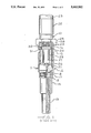
- FIG. 1 is a vertical view in partial section showing a high voltage ignition cable connector attached to an igniter according to the prior art
- FIG. 2 is an enlarged fragmentary vertical view in partial section showing a seal between a high voltage ignition cable connector and an igniter according to a first embodiment of the invention
- FIG. 3 is an enlarged fragmentary vertical view in partial section showing a seal between a high voltage ignition cable connector and an igniter according to a second embodiment of the invention
- FIG. 4 is an enlarged vertical view in partial section showing a fragmentary portion of a high voltage ignition cable connector according to a third embodiment of the invention.
- FIG. 5 is an enlarged fragmentary vertical view in partial section showing a seal between a high voltage ignition cable connector and an igniter according to the third embodiment of the invention.
- FIG. 1 of the drawings a prior art high voltage ignition cable connector 10 is shown attached to a conventional aviation engine igniter 11.
- the igniter 11 has a tubular shell 12 which may be formed from one or several sections.
- the shell 12 has a lower section 13, an intermediate section 14 and an upper section 15.
- the upper section 15 is in the form of a tubular sleeve and has an externally threaded end 16.
- a tubular insulator 17 is mounted in and shielded by the shell 12.
- a center electrode assembly 18 is mounted in a stepped axial bore 19 through the insulator 17.
- the insulator 17 has a free end 20 adjacent the threaded shell end 15.
- the center electrode 18 terminates at a terminal 21 recessed in the insulator bore 19 from the free end 20.
- the connector 10 has a ferrule 22 which is clamped onto the exterior of a shielded high voltage ignition cable 23.
- a coupling nut 24 retained on the ferrule 22 engages the threaded igniter shell end 16 to attach the connector 10 to the igniter 11.
- the connector 10 has a tubular insulator 25 which projects through the coupling nut 24 and terminates at a contact 26.
- the contact 26 is electrically connected to a high voltage conductor (not shown) inside of the ignition cable 23.
- the insulator 25 insulates the contact 26 from electrically grounded components including the connector ferrule 22, the cable shielding and the coupling nut 24.
- the connector insulator 25 is sized to slide into an end section 27 of the igniter insulator bore 19 above the terminal 21.
- the connector 10 When the connector 10 is attached to the igniter 11, the connector contact 26 contacts the igniter terminal 21.
- a first or inner spring 28 in the connector 10 urges the insulator 25 and the contact 26 into the igniter bore end section 27 to urge the contact 26 against the terminal 21 for maintaining a high voltage electrical connection at all times.
- the connector also includes a second or outer spring 29, a tubular spring retainer or cap 30 and a resilient annular seal 31. When the connector 10 is attached to the igniter 11, the spring 29 presses in an axial direction on the spring retainer 30 to compress the seal 31 against the igniter insulator end 20.
- a continuous annular seal is formed between the spring retainer 30 and the igniter insulator end 20 and the connector insulator 25.
- the purpose of the seal is to keep dirt, moisture and other contaminants from the annular region between the igniter insulator bore end section 27 and the connector insulator 25. However, under certain operating conditions, sufficient contaminants may enter this region to cause arcing from the high voltage terminal 21 and/or the contact 26 and the upper shell section 15.
- FIG. 2 is an enlarged fragmentary view, in partial section, of an improved seal 35 according to one embodiment of the invention located between an igniter shell 36, an igniter insulator 37, a connector insulator 38 and a retainer or cap 39 for a connector spring 40.
- the igniter insulator 37 has an end 41 and a cylindrical opening 42 in which a high voltage terminal (not shown) is recessed.
- the shell 36 has a cylindrical interior wall 43 which surrounds the igniter insulator 37 and extends past the insulator end 41.
- the exterior surface of the connector insulator 38 is stepped with an end portion 44 located toward the igniter having a diameter sized to pass into the igniter insulator opening 42, a smaller diameter portion 45 and a conical shoulder 46 extending between the insulator portions 44 and 45.
- the shoulder 46 faces generally toward the spring retainer 39.
- the seal 35 has a first portion 47 which terminates at an end 48 which abuts the shoulder 46.
- the first portion 47 has a wall thickness which permits the first portion 47 to pass into an annular space 49 formed between the connector insulator 38 and the igniter insulator 37 when the connector is secured to the igniter.
- the seal 35 has a second portion 50 having an end surface 51 which contacts the spring retainer 39 and, when the connector is secured to the igniter, a surface 52 which contacts the igniter insulator end 41.
- the spring retainer 39 contacts the seal 35 with a flat surface portion 53 and a conical surface portion 54 which surrounds the flat surface portion 53.
- the conical surface portion 54 is generally directed inwardly and toward the insulator shoulder 46.
- the spring 40 When the connector is secured to the igniter, the spring 40 is compressed and the spring retainer 39 exerts sufficient force on the resilient seal 35 to compress the seal 35 against the connector insulator shoulder 46 and the igniter insulator end 41. Sufficient force is exerted on the connector insulator shoulder 46 to cause the first seal portion 47 to bulge or expand in a radial direction, forming a seal between the igniter insulator 37 and the connector insulator 38. At the same time, sufficient force is exerted on the insulator end 41 to cause the second seal portion 50 to bulge or expand in a radial direction, forming a seal between the igniter insulator end 41, the adjacent shell wall 43 and the connector insulator 38. Thus, two distinct seal areas are formed between the igniter and the connector to prevent moisture and dirt from entering the annular space 49 formed between the insulators 37 and 38.
- FIG. 3 shows a modification of the seal 35 from FIG. 2. Similar parts shown in FIGS. 2 and 3 are labeled with the same reference numbers.
- the difference between the seal 35 of FIG. 2 and a modified seal 35' of FIG. 3 is that the first seal portion 47 has a conical surface 55 which abuts a conical surface portion 56 on the igniter insulator 37 adjacent the end 41.
- the conical surfaces 46 and 56 provide an annular wedge shape to the opening 49 about the axis of the igniter.
- the force exerted by the spring 40 and the spring retainer 39 on the seal 35' causes the first portion 47 of the seal 35' to wedge tightly between the igniter insulator 37 and the connector insulator 38.
- the second seal portion 50 is still compressed between the spring retainer 39 and the igniter insulator end 41 and expands to form a second seal area between the igniter insulator end 41, the interior shell wall 43 and the connector insulator 38.
- FIGS. 4 and 5 show a further embodiment of an igniter connector seal 60 according to the invention.
- the connector which is only partially shown, has an insulator 61 having an end 62 which supports a high voltage contact 63.
- the insulator 61 has a cylindrical exterior surface 64 in which an annular groove 65 is formed.
- the groove 65 has a smaller diameter than the diameter of the surface 64 and has a flat end 66 towards the insulator end 62 and a conical end 67 spaced further from the insulator end 62.
- the groove end 66 defines a shoulder on the insulator 61.
- the seal 60 is annular and extends around the connector insulator 61.
- the seal 60 has an interior surface area 68 which engages the groove 65, an end 69 which abuts the groove end 66, a surface area 70 which abuts the conical groove end 67 and a surface area 71 which engages a surface 72 of the insulator adjacent the conical end 67.
- the seal 60 further has a surface 73 which abuts a conical surface 74 on a retainer or cap 75 for a spring 76.
- the seal 60 has a first portion 77 adjacent the groove end 66 which normally has substantially the same exterior diameter as the connector insulator 61, a second portion 78 having a larger diameter and a third portion 79 which is located coaxially within the spring retainer 75.
- the third seal portion 79 centers the spring retainer 75 coaxially on the seal 60.
- FIG. 5 shows a portion of the connector positioned within the shell 80 of an igniter.
- the seal 60 is shown as it is deformed when the connector is secured to the igniter.
- An end 81 of an insulator 82 is located within the shell 80.
- the first seal portion 77 extends into a bore 83 in the insulator 82.
- Compressing the first seal portion 77 against the shoulder formed by the groove end 66 causes it to expand or bulge in a radial direction at 84 to form an annular seal between the connector insulator 61 and the igniter insulator 82.
- Compressing the second seal portion 78 against the igniter insulator end 81 causes it to expand or bulge both inwardly and outwardly in a radial direction at 85 to form an annular seal between the igniter insulator 61, an interior wall 86 of the shell 80, and the igniter insulator end 81.
- seal 60 between the igniter and the connector to reduce the risk of moisture, dirt and other contaminant from entering an annular space 87 between the bore 83 in the igniter insulator 82 and the connector insulator 61. Accordingly, the risk of a failure of the igniter caused by arcing between the igniter and the connector is reduced.
- the seal of the invention need not seal against the igniter shell to effectively form multiple seal areas between the igniter and connector insulators. However, when the seal is deformed sufficiently to press against the igniter shell, the inwardly directed force between the seal and the connector insulator is increased. It will be appreciated that various modifications and changes may be made in the above described preferred embodiments of a seal for an igniter cable connector without departing from the spirit and the scope of the following claims.
Landscapes
- Engineering & Computer Science (AREA)
- Chemical & Material Sciences (AREA)
- Combustion & Propulsion (AREA)
- Mechanical Engineering (AREA)
- General Engineering & Computer Science (AREA)
- Connector Housings Or Holding Contact Members (AREA)
Abstract
Description
Claims (12)
Priority Applications (1)
| Application Number | Priority Date | Filing Date | Title |
|---|---|---|---|
| US07/728,860 US5083932A (en) | 1990-02-15 | 1991-07-11 | Igniter cable connector seal |
Applications Claiming Priority (2)
| Application Number | Priority Date | Filing Date | Title |
|---|---|---|---|
| US48043990A | 1990-02-15 | 1990-02-15 | |
| US07/728,860 US5083932A (en) | 1990-02-15 | 1991-07-11 | Igniter cable connector seal |
Related Parent Applications (1)
| Application Number | Title | Priority Date | Filing Date |
|---|---|---|---|
| US48043990A Continuation | 1990-02-15 | 1990-02-15 |
Publications (1)
| Publication Number | Publication Date |
|---|---|
| US5083932A true US5083932A (en) | 1992-01-28 |
Family
ID=27046588
Family Applications (1)
| Application Number | Title | Priority Date | Filing Date |
|---|---|---|---|
| US07/728,860 Expired - Lifetime US5083932A (en) | 1990-02-15 | 1991-07-11 | Igniter cable connector seal |
Country Status (1)
| Country | Link |
|---|---|
| US (1) | US5083932A (en) |
Cited By (7)
| Publication number | Priority date | Publication date | Assignee | Title |
|---|---|---|---|---|
| US5593308A (en) * | 1992-09-25 | 1997-01-14 | Sumitomo Wiring Systems, Ltd. | Connecting assembly for ignition plug in gasoline engine and method for producing same |
| US6582220B2 (en) * | 1999-07-30 | 2003-06-24 | Alstom Power Inc. | Ignitor assembly for a fossil fuel-fired power generation system |
| US7001195B2 (en) | 2003-05-22 | 2006-02-21 | Champion Aerospace Inc. | Ignition lead with replaceable terminal contact |
| US20060059885A1 (en) * | 2004-09-08 | 2006-03-23 | Johnson Howard R | Two piece jet engine igniter assembly |
| US20060180111A1 (en) * | 2005-02-15 | 2006-08-17 | Champion Aerospace, Inc. | Air-cooled ignition lead |
| CN107408778A (en) * | 2015-03-25 | 2017-11-28 | 株式会社自动网络技术研究所 | The manufacture method of Belt connector electric wire and Belt connector electric wire |
| US10502320B2 (en) * | 2014-09-02 | 2019-12-10 | Rohr, Inc. | Spring retainer seal |
Citations (15)
| Publication number | Priority date | Publication date | Assignee | Title |
|---|---|---|---|---|
| US2129961A (en) * | 1937-03-27 | 1938-09-13 | Gen Motors Corp | Radio shielded spark plug |
| US2238397A (en) * | 1940-07-15 | 1941-04-15 | Gen Motors Corp | Radio shielded spark plug |
| US2351066A (en) * | 1942-05-15 | 1944-06-13 | Gen Electric | Electrical discharge device |
| US2365219A (en) * | 1942-09-16 | 1944-12-19 | John J Rose | Flashover prevention means for high-tension ignition apparatus |
| US2399390A (en) * | 1942-04-13 | 1946-04-30 | Titeflex Inc | Radio-shielded connection, especially for spark plugs |
| US2459286A (en) * | 1944-05-27 | 1949-01-18 | Gen Motors Corp | Combination spark plug and fuel injector |
| GB684804A (en) * | 1949-12-22 | 1952-12-24 | Bendix Aviat Corp | Improvements in or relating to detachable electrical connections |
| US2651298A (en) * | 1947-12-26 | 1953-09-08 | Bendix Aviat Corp | Ignition apparatus and method of making same |
| US2913696A (en) * | 1956-11-02 | 1959-11-17 | Bendix Aviat Corp | Electrical apparatus |
| US3050658A (en) * | 1961-01-11 | 1962-08-21 | Gen Motors Corp | Quick detachable, shielded electrical connector |
| US3076113A (en) * | 1961-03-29 | 1963-01-29 | Gen Motors Corp | Spark plug and connector device therefor |
| US3334326A (en) * | 1965-07-06 | 1967-08-01 | Skytronics Inc | Moisture proof connector for spark plugs |
| US4145106A (en) * | 1977-10-31 | 1979-03-20 | Livingston Industries, Incorporated | Shielding device for oriented spark plugs |
| US4266841A (en) * | 1979-10-25 | 1981-05-12 | The Bendix Corporation | High voltage cable terminal |
| US4978309A (en) * | 1989-03-17 | 1990-12-18 | Champion Spark Plug Company | Igniter cable connector |
-
1991
- 1991-07-11 US US07/728,860 patent/US5083932A/en not_active Expired - Lifetime
Patent Citations (15)
| Publication number | Priority date | Publication date | Assignee | Title |
|---|---|---|---|---|
| US2129961A (en) * | 1937-03-27 | 1938-09-13 | Gen Motors Corp | Radio shielded spark plug |
| US2238397A (en) * | 1940-07-15 | 1941-04-15 | Gen Motors Corp | Radio shielded spark plug |
| US2399390A (en) * | 1942-04-13 | 1946-04-30 | Titeflex Inc | Radio-shielded connection, especially for spark plugs |
| US2351066A (en) * | 1942-05-15 | 1944-06-13 | Gen Electric | Electrical discharge device |
| US2365219A (en) * | 1942-09-16 | 1944-12-19 | John J Rose | Flashover prevention means for high-tension ignition apparatus |
| US2459286A (en) * | 1944-05-27 | 1949-01-18 | Gen Motors Corp | Combination spark plug and fuel injector |
| US2651298A (en) * | 1947-12-26 | 1953-09-08 | Bendix Aviat Corp | Ignition apparatus and method of making same |
| GB684804A (en) * | 1949-12-22 | 1952-12-24 | Bendix Aviat Corp | Improvements in or relating to detachable electrical connections |
| US2913696A (en) * | 1956-11-02 | 1959-11-17 | Bendix Aviat Corp | Electrical apparatus |
| US3050658A (en) * | 1961-01-11 | 1962-08-21 | Gen Motors Corp | Quick detachable, shielded electrical connector |
| US3076113A (en) * | 1961-03-29 | 1963-01-29 | Gen Motors Corp | Spark plug and connector device therefor |
| US3334326A (en) * | 1965-07-06 | 1967-08-01 | Skytronics Inc | Moisture proof connector for spark plugs |
| US4145106A (en) * | 1977-10-31 | 1979-03-20 | Livingston Industries, Incorporated | Shielding device for oriented spark plugs |
| US4266841A (en) * | 1979-10-25 | 1981-05-12 | The Bendix Corporation | High voltage cable terminal |
| US4978309A (en) * | 1989-03-17 | 1990-12-18 | Champion Spark Plug Company | Igniter cable connector |
Cited By (10)
| Publication number | Priority date | Publication date | Assignee | Title |
|---|---|---|---|---|
| US5593308A (en) * | 1992-09-25 | 1997-01-14 | Sumitomo Wiring Systems, Ltd. | Connecting assembly for ignition plug in gasoline engine and method for producing same |
| US6582220B2 (en) * | 1999-07-30 | 2003-06-24 | Alstom Power Inc. | Ignitor assembly for a fossil fuel-fired power generation system |
| US7001195B2 (en) | 2003-05-22 | 2006-02-21 | Champion Aerospace Inc. | Ignition lead with replaceable terminal contact |
| US20060059885A1 (en) * | 2004-09-08 | 2006-03-23 | Johnson Howard R | Two piece jet engine igniter assembly |
| US7065956B2 (en) * | 2004-09-08 | 2006-06-27 | Howard Johnson | Two piece jet engine igniter assembly |
| US20060180111A1 (en) * | 2005-02-15 | 2006-08-17 | Champion Aerospace, Inc. | Air-cooled ignition lead |
| US7124724B2 (en) | 2005-02-15 | 2006-10-24 | Champion Aerospace, Inc. | Air-cooled ignition lead |
| US10502320B2 (en) * | 2014-09-02 | 2019-12-10 | Rohr, Inc. | Spring retainer seal |
| CN107408778A (en) * | 2015-03-25 | 2017-11-28 | 株式会社自动网络技术研究所 | The manufacture method of Belt connector electric wire and Belt connector electric wire |
| CN107408778B (en) * | 2015-03-25 | 2019-09-27 | 株式会社自动网络技术研究所 | The manufacturing method of Belt connector electric wire and Belt connector electric wire |
Similar Documents
| Publication | Publication Date | Title |
|---|---|---|
| US4241374A (en) | Surge voltage arrester with ventsafe feature | |
| US5310359A (en) | Cable connector with strain relief | |
| US5722856A (en) | Apparatus for electrical connection of a coaxial cable and a connector | |
| KR100744975B1 (en) | Multipolar connector | |
| US3960692A (en) | Electro-chemical sensor construction | |
| US3994553A (en) | Discharge resistant cable connector | |
| US5766030A (en) | Cap type connector assembly for high-voltage cable | |
| US5283499A (en) | Igniter and cable connector assembly | |
| JPS6318840B2 (en) | ||
| GB2277207A (en) | Clamping a coaxial connector to a corrugated cable shield | |
| US5716223A (en) | Spark plug boot insulator | |
| US4266841A (en) | High voltage cable terminal | |
| US7768183B2 (en) | Extension spark plug | |
| US5083932A (en) | Igniter cable connector seal | |
| US5340332A (en) | Coaxial cable connector | |
| US6262374B1 (en) | Shielded cable connecting structure | |
| US4978309A (en) | Igniter cable connector | |
| US5382170A (en) | Coupling construction | |
| US6048227A (en) | Connector backshell | |
| US5332394A (en) | Electrical connector for connecting a voltage source to a spark plug terminal | |
| US4707047A (en) | Environmentally sealed electrical connector | |
| US2087920A (en) | Liquidproof electrical joint | |
| US3829800A (en) | Hf coaxial plug connector | |
| US2397735A (en) | Coupling device | |
| US5381773A (en) | Modular ignition system |
Legal Events
| Date | Code | Title | Description |
|---|---|---|---|
| STCF | Information on status: patent grant |
Free format text: PATENTED CASE |
|
| FPAY | Fee payment |
Year of fee payment: 4 |
|
| AS | Assignment |
Owner name: CHAMPION SPARK PLUG COMPANY, TEXAS Free format text: ASSIGNMENT OF ASSIGNORS INTEREST;ASSIGNOR:COOPER INDUSTRIES, INC.;REEL/FRAME:008920/0600 Effective date: 19980101 |
|
| FPAY | Fee payment |
Year of fee payment: 8 |
|
| AS | Assignment |
Owner name: WILMINGTON TRUST COMPANY, AS TRUSTEE, DELAWARE Free format text: SECURITY AGREEMENT;ASSIGNOR:FEDERAL-MOGUL WORLD WIDE, INC. (MI CORPORATION);REEL/FRAME:011571/0001 Effective date: 20001229 |
|
| AS | Assignment |
Owner name: FEDERAL-MOGUL IGNITION COMPANY, MICHIGAN Free format text: CHANGE OF NAME;ASSIGNOR:CHAMPION SPARK PLUG COMPANY;REEL/FRAME:011796/0310 Effective date: 19981029 |
|
| AS | Assignment |
Owner name: BANKERS TRUST COMPANY, NEW YORK Free format text: SECURITY AGREEMENT;ASSIGNOR:AVIATION ACQUISITION CORPORATION;REEL/FRAME:012059/0764 Effective date: 20010530 |
|
| AS | Assignment |
Owner name: AVIATION ACQUISITION CORPORATION, OHIO Free format text: ASSIGNMENT OF ASSIGNORS INTEREST;ASSIGNOR:FEDERAL-MOGUL IGNITION COMPANY;REEL/FRAME:012188/0143 Effective date: 20010531 |
|
| AS | Assignment |
Owner name: CHAMPION AEROSPACE INC., SOUTH CAROLINA Free format text: CHANGE OF NAME;ASSIGNOR:AVIATION ACQUISITION CORPORATION;REEL/FRAME:012199/0601 Effective date: 20010601 |
|
| FPAY | Fee payment |
Year of fee payment: 12 |
|
| AS | Assignment |
Owner name: AVIATION ACQUISITION CORPORATION, SOUTH CAROLINA Free format text: ASSIGNMENT OF ASSIGNORS INTEREST;ASSIGNOR:BANKERS TRUST COMPANY, N/K/A DEUTSCHE BANK TRUST COMPANY AMERICAS;REEL/FRAME:014332/0369 Effective date: 20030722 Owner name: AVIATION ACQUISITION CORPORATION, SOUTH CAROLINA Free format text: ASSIGNMENT OF ASSIGNORS INTEREST;ASSIGNOR:WILMINGTON TRUST COMPANY;REEL/FRAME:014332/0352 Effective date: 20030722 |
|
| AS | Assignment |
Owner name: CREDIT SUISSE FIRST BOSTON, AS COLLATERAL AGENT, N Free format text: SECURITY AGREEMENT;ASSIGNOR:CHAMPION AEROSPACE INC.;REEL/FRAME:014327/0647 Effective date: 20030722 |
|
| AS | Assignment |
Owner name: CREDIT SUISSE, CAYMAN ISLANDS BRANCH, NEW YORK Free format text: SECURITY AGREEMENT;ASSIGNOR:CHAMPION AEROSPACE INC.;REEL/FRAME:017833/0292 Effective date: 20060623 |
|
| AS | Assignment |
Owner name: CHAMPION AEROSPACE LLC, SOUTH CAROLINA Free format text: CHANGE OF NAME;ASSIGNOR:CHAMPION AEROSPACE INC.;REEL/FRAME:019754/0258 Effective date: 20070625 |
|
| AS | Assignment |
Owner name: CREDIT SUISSE AG, AS ADMINISTRATIVE AND COLLATERAL Free format text: SECURITY AGREEMENT;ASSIGNORS:TRANSDIGM INC.;TRANSDIGM GROUP INCORPORATED;HARTWELL CORPORATION;AND OTHERS;REEL/FRAME:025810/0177 Effective date: 20110214 |