US5083274A - Railroad brake pressure recording - Google Patents
Railroad brake pressure recording Download PDFInfo
- Publication number
- US5083274A US5083274A US07/486,137 US48613790A US5083274A US 5083274 A US5083274 A US 5083274A US 48613790 A US48613790 A US 48613790A US 5083274 A US5083274 A US 5083274A
- Authority
- US
- United States
- Prior art keywords
- air brake
- analogue
- input
- brake pressure
- manifold
- Prior art date
- Legal status (The legal status is an assumption and is not a legal conclusion. Google has not performed a legal analysis and makes no representation as to the accuracy of the status listed.)
- Expired - Fee Related
Links
- 238000000034 method Methods 0.000 claims description 6
- 230000008569 process Effects 0.000 claims description 6
- 238000013500 data storage Methods 0.000 claims description 3
- 238000009825 accumulation Methods 0.000 claims 1
- 230000009467 reduction Effects 0.000 description 5
- 238000010586 diagram Methods 0.000 description 4
- 238000004891 communication Methods 0.000 description 2
- 239000004020 conductor Substances 0.000 description 2
- 230000006870 function Effects 0.000 description 2
- 230000013011 mating Effects 0.000 description 2
- 230000007704 transition Effects 0.000 description 2
- 230000004397 blinking Effects 0.000 description 1
- QWCRAEMEVRGPNT-UHFFFAOYSA-N buspirone Chemical group C1C(=O)N(CCCCN2CCN(CC2)C=2N=CC=CN=2)C(=O)CC21CCCC2 QWCRAEMEVRGPNT-UHFFFAOYSA-N 0.000 description 1
- 230000008859 change Effects 0.000 description 1
- 238000006243 chemical reaction Methods 0.000 description 1
- 230000008878 coupling Effects 0.000 description 1
- 238000010168 coupling process Methods 0.000 description 1
- 238000005859 coupling reaction Methods 0.000 description 1
- 230000009977 dual effect Effects 0.000 description 1
- 230000003137 locomotive effect Effects 0.000 description 1
- 230000004048 modification Effects 0.000 description 1
- 238000012986 modification Methods 0.000 description 1
- 239000007787 solid Substances 0.000 description 1
Images

Classifications
-
- G—PHYSICS
- G01—MEASURING; TESTING
- G01D—MEASURING NOT SPECIALLY ADAPTED FOR A SPECIFIC VARIABLE; ARRANGEMENTS FOR MEASURING TWO OR MORE VARIABLES NOT COVERED IN A SINGLE OTHER SUBCLASS; TARIFF METERING APPARATUS; MEASURING OR TESTING NOT OTHERWISE PROVIDED FOR
- G01D9/00—Recording measured values
-
- B—PERFORMING OPERATIONS; TRANSPORTING
- B60—VEHICLES IN GENERAL
- B60T—VEHICLE BRAKE CONTROL SYSTEMS OR PARTS THEREOF; BRAKE CONTROL SYSTEMS OR PARTS THEREOF, IN GENERAL; ARRANGEMENT OF BRAKING ELEMENTS ON VEHICLES IN GENERAL; PORTABLE DEVICES FOR PREVENTING UNWANTED MOVEMENT OF VEHICLES; VEHICLE MODIFICATIONS TO FACILITATE COOLING OF BRAKES
- B60T17/00—Component parts, details, or accessories of power brake systems not covered by groups B60T8/00, B60T13/00 or B60T15/00, or presenting other characteristic features
- B60T17/18—Safety devices; Monitoring
- B60T17/22—Devices for monitoring or checking brake systems; Signal devices
- B60T17/228—Devices for monitoring or checking brake systems; Signal devices for railway vehicles
Definitions
- the present invention generally relates to the field of railroad brake pressure recording, and more particularly to a recorder which is plug compatible with both analogue and digital air brake pressure manifolds.
- an air brake pressure manifold is used to report air brake pressure to the train operator. Historically, this pressure has been reported in terms of discrete, incremental reductions from the maximum pressure to which the train's brake system had been charged.
- a three digit binary code is used to designate seven discrete pressure reduction levels plus an emergency condition.
- a three conductor bus carries the binary coded pressure information to an operator display, which may be part of the manifold, and to three output pins to which a recorder external to the manifold can be connected.
- analogue brake pressure manifolds that measure and report the absolute air brake pressure over a continuous range.
- These manifolds employ a pressure to frequency convertor which, for example, may be calibrated so as to provide an output signal from zero to 100 Hz over a brake pressure range from zero to the maximum pressure to which the system will be charged.
- a related object of this invention is the provision of a recorder which is responsive to the communication protocol; a recorder which is pin compatible with presently installed digital manifolds; a recorder which does not sacrifice any connector pins or recorder channels.
- this invention contemplates the provision of a protocol in which the variable frequency output signal of an analogue air manifold is connected to a predetermined pin position.
- an analogue manifold transmits a minimum frequency signal at this pin position to identify itself as an analogue manifold.
- the recorder looks for the presence or absence of this minimum frequency signal and couples information from the binary bus pin positions to the recording medium if a frequency signal is absent and couples information from the analogue pin position to the medium if the frequency signal is present.
- the recorder can use the pins and channels previously assigned to be used for the manifold bus for any other purpose, such as inputs for recording on-off events.
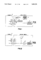
- FIG. 1 is a schematic block diagram of a digital air brake pressure manifold
- FIG. 2 is a schematic block diagram of an analogue air brake pressure manifold
- FIG. 3 is a block diagram of a recorder which is plug compatible with both digital and analogue air brake manifolds observing the protocol of this invention.
- FIG. 1 shows a block diagram of a digital air brake manifold of the type commonly installed in railway locomotives at the present time. It comprises: a pressure to digital transducer 12; a digital storage 14 that stores the maximum pressure to which the brake system is charged; a comparator 16 that compares the output of the transducer 12 to the stored maximum pressure; a brake pressure reduction display 18; and a three conductor bus 20 for coupling the binary brake pressure reduction status to a three element output designated in the drawing as pin connectors C, D, and E.
- the respective mating members which establish electrical connection between the manifold and the recorder are referred to herein as pins and pin connectors as is customary in the art.
- the connectors are adapted to be connected to a recorder 21, such as the Pulse model TTX-REC-06H recorder.
- the output connector of a digital air brake manifold includes an additional output pin at a predetermined position, pin J illustrated in the drawing, that is not for recording digital air brake pressure reductions.
- an analogue manifold has a pressure to transducer 24, which may be of a suitable commercially available design. It will be appreciated by those skilled in the art, the pressure to frequency conversion may be accomplished with two discrete commercially available components; a pressure-to-voltage convertor 24 (e.g. 0-5 volts) and a voltage-to-frequency convertor 25. The output of the voltage-to-frequency convertor 25 is coupled to output position J. The output frequency varies as the brake pressure input varies.
- an analogue manifold may be calibrated to have an output signal frequency which ranges from zero Hz to 100 Hz over input brake air pressure range, say from zero to 100 psi.
- the analogue manifold may include a suitable display such as an LED 27 blinking on and off at a rate proportional to the frequency to indicate proper operation of the unit.
- a protocol is established whereby the analogue manifold maintains a minimum low frequency signal at pin position J even in the absence of an input pressure to the manifold. This is accomplished in accordance with the preferred embodiment of the invention by adjusting the calibration so that, for example, the output signal varies from 15 Hz to 115 Hz as the input pressure varies from zero to maximum pressure.
- a recorder in accordance with this invention has input connectors C, D, E and J positioned to mate respectively with connector positions C, D, E and J of both analogue and digital air manifolds.
- the recorder of this invention determines the type of manifold to which it is connected by the signal at input J, the input signal line for an analogue manifold. It will be appreciated that in having input J serve this dual function, the requirement for an extra input pin position to indicate the type of manifold is eliminated.
- a microprocessor 28 formats both digital manifold inputs from inputs C, D and E and analogue inputs from J.
- the formatted output of microprocessor 28 is transferred to a suitable data storage device 36, such as a removable solid state memory, for example.
- Pin J is coupled to the input of a counter 32 whose output is coupled to microprocessor 28.
- the counter accumulates a count over a predetermined fixed interval (e.g. 1 second). The count is a function of the frequency of the signal coupled to connector J. The accumulated count is transferred to the microprocessor 28 at the end of the predetermined fixed interval (e.g., 1 second). The microprocessor retains these counts in memory. If the total count of a predetermined number of these intervals (e.g., 60 intervals) is more than a predetermined number, the microprocessor 28 is programmed to recognize inputs from connectors C, D, E and J as data from an analogue manifold.
- Counts for successive intervals are processed by the microprocessor and stored as a record of brake pressure.
- the protocol requires that an analogue manifold maintain a minimum frequency signal at ZERO input.
- the microprocessor also will process inputs, if any, from connectors C, D, and E as inputs from an analogue manifold, e.g., on-off inputs, or any other input- these pins are not necessary in the analogue manifold for transferring brake pressure information to the recorder.
- the microprocessor is programmed to process inputs from connectors C, D and E as digital manifold inputs and store data from these inputs as a record of brake pressure data.
- Criteria to be met for at least two consecutive 60 second periods before a change of state is recognized are considered. Note: This last requirement is added to make the system more noise immune.
Landscapes
- Engineering & Computer Science (AREA)
- Physics & Mathematics (AREA)
- General Physics & Mathematics (AREA)
- Transportation (AREA)
- Mechanical Engineering (AREA)
- Braking Systems And Boosters (AREA)
Abstract
Description
Claims (3)
Priority Applications (1)
| Application Number | Priority Date | Filing Date | Title |
|---|---|---|---|
| US07/486,137 US5083274A (en) | 1990-02-28 | 1990-02-28 | Railroad brake pressure recording |
Applications Claiming Priority (1)
| Application Number | Priority Date | Filing Date | Title |
|---|---|---|---|
| US07/486,137 US5083274A (en) | 1990-02-28 | 1990-02-28 | Railroad brake pressure recording |
Publications (1)
| Publication Number | Publication Date |
|---|---|
| US5083274A true US5083274A (en) | 1992-01-21 |
Family
ID=23930741
Family Applications (1)
| Application Number | Title | Priority Date | Filing Date |
|---|---|---|---|
| US07/486,137 Expired - Fee Related US5083274A (en) | 1990-02-28 | 1990-02-28 | Railroad brake pressure recording |
Country Status (1)
| Country | Link |
|---|---|
| US (1) | US5083274A (en) |
Cited By (10)
| Publication number | Priority date | Publication date | Assignee | Title |
|---|---|---|---|---|
| WO1998010967A1 (en) * | 1996-09-13 | 1998-03-19 | New York Air Brake Corporation | Modular locomotive brake controller |
| RU2136850C1 (en) * | 1998-05-07 | 1999-09-10 | Государственный научно-исследовательский институт горной геомеханики и маркшейдерского дела - Межотраслевой научный центр | Method for extracting methane from coal seams |
| US6098006A (en) * | 1996-09-13 | 2000-08-01 | New York Air Brake Corporation | Modular locomotive brake controller |
| RU2206718C2 (en) * | 1998-09-02 | 2003-06-20 | Раг Акциенгезельшафт | Method of intraseam gas recovery from coal seams |
| US7073753B2 (en) | 1996-09-13 | 2006-07-11 | New York Airbrake Corporation | Integrated train control |
| RU2386014C2 (en) * | 2007-11-30 | 2010-04-10 | Общество с ограниченной ответственностью "Кубаньгазпром" | Method of reduction of man's impact on environment during operation of natural gas field and underground gas storages |
| EP2097303B1 (en) * | 2006-12-01 | 2017-11-08 | Wabtec Holding Corporation | Freight car event recorder |
| US20180015873A1 (en) * | 2016-07-18 | 2018-01-18 | Bendix Commercial Vehicle Systems Llc | Controller for Controlling a Vehicle Stop Light |
| US10363917B2 (en) | 2016-12-14 | 2019-07-30 | Davanac Inc. | Enhanced railway equipment and related integrated systems |
| CN111873978A (en) * | 2020-07-10 | 2020-11-03 | 中车齐齐哈尔车辆有限公司 | Method and system for monitoring pressure of train pipe |
Citations (5)
| Publication number | Priority date | Publication date | Assignee | Title |
|---|---|---|---|---|
| US4236215A (en) * | 1978-10-26 | 1980-11-25 | Vapor Corporation | Vehicular data handling and control system |
| US4553723A (en) * | 1983-09-15 | 1985-11-19 | Harris Corporation | Railroad air brake system |
| US4582280A (en) * | 1983-09-14 | 1986-04-15 | Harris Corporation | Railroad communication system |
| US4755803A (en) * | 1987-05-27 | 1988-07-05 | Pulse Electronics, Inc. | Air brake manifold all level reset |
| US4906970A (en) * | 1986-07-23 | 1990-03-06 | Nissan Motor Co., Ltd. | Vehicle on-board diagnosing system |
-
1990
- 1990-02-28 US US07/486,137 patent/US5083274A/en not_active Expired - Fee Related
Patent Citations (5)
| Publication number | Priority date | Publication date | Assignee | Title |
|---|---|---|---|---|
| US4236215A (en) * | 1978-10-26 | 1980-11-25 | Vapor Corporation | Vehicular data handling and control system |
| US4582280A (en) * | 1983-09-14 | 1986-04-15 | Harris Corporation | Railroad communication system |
| US4553723A (en) * | 1983-09-15 | 1985-11-19 | Harris Corporation | Railroad air brake system |
| US4906970A (en) * | 1986-07-23 | 1990-03-06 | Nissan Motor Co., Ltd. | Vehicle on-board diagnosing system |
| US4755803A (en) * | 1987-05-27 | 1988-07-05 | Pulse Electronics, Inc. | Air brake manifold all level reset |
Cited By (14)
| Publication number | Priority date | Publication date | Assignee | Title |
|---|---|---|---|---|
| AU716297B2 (en) * | 1996-09-13 | 2000-02-24 | New York Air Brake Llc | Modular locomotive brake controller |
| US6098006A (en) * | 1996-09-13 | 2000-08-01 | New York Air Brake Corporation | Modular locomotive brake controller |
| US7073753B2 (en) | 1996-09-13 | 2006-07-11 | New York Airbrake Corporation | Integrated train control |
| WO1998010967A1 (en) * | 1996-09-13 | 1998-03-19 | New York Air Brake Corporation | Modular locomotive brake controller |
| RU2136850C1 (en) * | 1998-05-07 | 1999-09-10 | Государственный научно-исследовательский институт горной геомеханики и маркшейдерского дела - Межотраслевой научный центр | Method for extracting methane from coal seams |
| RU2206718C2 (en) * | 1998-09-02 | 2003-06-20 | Раг Акциенгезельшафт | Method of intraseam gas recovery from coal seams |
| EP2097303B1 (en) * | 2006-12-01 | 2017-11-08 | Wabtec Holding Corporation | Freight car event recorder |
| RU2386014C2 (en) * | 2007-11-30 | 2010-04-10 | Общество с ограниченной ответственностью "Кубаньгазпром" | Method of reduction of man's impact on environment during operation of natural gas field and underground gas storages |
| US20180015873A1 (en) * | 2016-07-18 | 2018-01-18 | Bendix Commercial Vehicle Systems Llc | Controller for Controlling a Vehicle Stop Light |
| US10358118B2 (en) * | 2016-07-18 | 2019-07-23 | Bendix Commercial Vehicle Systems Llc | Controller for controlling a vehicle stop light |
| US10363917B2 (en) | 2016-12-14 | 2019-07-30 | Davanac Inc. | Enhanced railway equipment and related integrated systems |
| US11400911B2 (en) | 2016-12-14 | 2022-08-02 | Davanac Inc. | Enhanced railway equipment and related integrated systems |
| CN111873978A (en) * | 2020-07-10 | 2020-11-03 | 中车齐齐哈尔车辆有限公司 | Method and system for monitoring pressure of train pipe |
| CN111873978B (en) * | 2020-07-10 | 2021-11-12 | 中车齐齐哈尔车辆有限公司 | Method and system for monitoring pressure of train pipe |
Similar Documents
| Publication | Publication Date | Title |
|---|---|---|
| US5083274A (en) | Railroad brake pressure recording | |
| US5185700A (en) | Solid state event recorder | |
| US5065321A (en) | Solid state event recorder | |
| EP0488673B1 (en) | Matrix switcher apparatus | |
| US6049296A (en) | Automatic train serialization with car orientation | |
| EP0845131B1 (en) | Electronic diagnostic system | |
| US6172619B1 (en) | Automatic train serialization with car orientation | |
| US5379441A (en) | Homebus system for permitting homebus equipment and ISDN basic interface equipment to use same twisted pair line homebus | |
| US5937033A (en) | Telephone system diagnostic measurement system including a distant terminal drop test measurement circuit | |
| US3864731A (en) | Vehicle data recorder employing data compression | |
| GB2327764A (en) | Measuring system with exchangeable sensors | |
| CA2177649A1 (en) | Zero byte substitution method and apparatus for telecommunications equipment | |
| EP0698542A1 (en) | Trainline system using an electromagnetic communication link | |
| EP0203662B1 (en) | A communication system | |
| US5581472A (en) | Method and apparatus for feedback of trainline status to the central processor of a locomotive throttle controller | |
| US3938092A (en) | System for telecommunicating vehicle operation data between a ground station and a remote data processing station | |
| US5966084A (en) | Automatic train serialization with car orientation | |
| JP2527771B2 (en) | Input control circuit in programmable automaton | |
| US6626034B2 (en) | Conventional brake pipe continuity test | |
| US5623515A (en) | Data communication system for reducing a risk of transmission errors | |
| US20010032061A1 (en) | Data logging | |
| CN215851194U (en) | Pressure monitoring system and double-section double-heading locomotive | |
| DE4339906C2 (en) | Method and device for monitoring faults in an electronic communication system | |
| US5222129A (en) | Telephone charging signalling detector suitable for central office line interface circuits | |
| JPH02219324A (en) | Underwater wire type data collection system |
Legal Events
| Date | Code | Title | Description |
|---|---|---|---|
| AS | Assignment |
Owner name: PULSE ELECTRONICS, INC., MARYLAND Free format text: ASSIGNMENT OF ASSIGNORS INTEREST.;ASSIGNORS:BEZOS, ANGEL P.;FERNANDEZ, EMILIO A.;REEL/FRAME:005245/0848 Effective date: 19900206 |
|
| FEPP | Fee payment procedure |
Free format text: PAYOR NUMBER ASSIGNED (ORIGINAL EVENT CODE: ASPN); ENTITY STATUS OF PATENT OWNER: LARGE ENTITY |
|
| AS | Assignment |
Owner name: PULSE ELECTRONICS, INC. A DELAWARE CORPORATION Free format text: ASSIGNMENT OF ASSIGNORS INTEREST;ASSIGNOR:PULSE ELECTRONICS, INC., A VIRGINIA CORPORATION;REEL/FRAME:007338/0120 Effective date: 19950131 |
|
| FPAY | Fee payment |
Year of fee payment: 4 |
|
| FEPP | Fee payment procedure |
Free format text: PAYOR NUMBER ASSIGNED (ORIGINAL EVENT CODE: ASPN); ENTITY STATUS OF PATENT OWNER: LARGE ENTITY Free format text: PAYER NUMBER DE-ASSIGNED (ORIGINAL EVENT CODE: RMPN); ENTITY STATUS OF PATENT OWNER: LARGE ENTITY |
|
| AS | Assignment |
Owner name: CHASE MANHATTAN BANK, THE, NEW YORK Free format text: SECURITY INTEREST;ASSIGNOR:WESTINGHOUSE AIR BRAKE COMPANY;REEL/FRAME:009423/0239 Effective date: 19980630 |
|
| AS | Assignment |
Owner name: WESTINGHOUSE AIR BRAKE COMPANY, PENNSYLVANIA Free format text: ASSIGNMENT OF ASSIGNORS INTEREST;ASSIGNOR:PULSE ELECTRONICS, INC;REEL/FRAME:010144/0879 Effective date: 19971231 |
|
| REMI | Maintenance fee reminder mailed | ||
| FEPP | Fee payment procedure |
Free format text: PETITION RELATED TO MAINTENANCE FEES FILED (ORIGINAL EVENT CODE: PMFP); ENTITY STATUS OF PATENT OWNER: LARGE ENTITY |
|
| FEPP | Fee payment procedure |
Free format text: PETITION RELATED TO MAINTENANCE FEES GRANTED (ORIGINAL EVENT CODE: PMFG); ENTITY STATUS OF PATENT OWNER: LARGE ENTITY |
|
| FP | Lapsed due to failure to pay maintenance fee |
Effective date: 20000121 |
|
| SULP | Surcharge for late payment | ||
| PRDP | Patent reinstated due to the acceptance of a late maintenance fee |
Effective date: 20000602 |
|
| AS | Assignment |
Owner name: WESTINGHOUSE AIR BRAKE COMPANY, PENNSYLVANIA Free format text: TERMINATION OF SECURITY INTEREST RECORDAL STARTING AT REEL/FRAME 9423/0239.;ASSIGNOR:CHASE MANHATTAN BANK, AS COLLATERAL AGENT, THE;REEL/FRAME:012280/0283 Effective date: 20010501 |
|
| FEPP | Fee payment procedure |
Free format text: PAYER NUMBER DE-ASSIGNED (ORIGINAL EVENT CODE: RMPN); ENTITY STATUS OF PATENT OWNER: LARGE ENTITY Free format text: PAYOR NUMBER ASSIGNED (ORIGINAL EVENT CODE: ASPN); ENTITY STATUS OF PATENT OWNER: LARGE ENTITY |
|
| REMI | Maintenance fee reminder mailed | ||
| LAPS | Lapse for failure to pay maintenance fees | ||
| STCH | Information on status: patent discontinuation |
Free format text: PATENT EXPIRED DUE TO NONPAYMENT OF MAINTENANCE FEES UNDER 37 CFR 1.362 |
|
| FP | Lapsed due to failure to pay maintenance fee |
Effective date: 20040121 |