US507500A - Process of and apparatus for making and burning fuel-gas - Google Patents
Process of and apparatus for making and burning fuel-gas Download PDFInfo
- Publication number
- US507500A US507500A US507500DA US507500A US 507500 A US507500 A US 507500A US 507500D A US507500D A US 507500DA US 507500 A US507500 A US 507500A
- Authority
- US
- United States
- Prior art keywords
- products
- steam
- oil
- furnace
- combustion
- Prior art date
- Legal status (The legal status is an assumption and is not a legal conclusion. Google has not performed a legal analysis and makes no representation as to the accuracy of the status listed.)
- Expired - Lifetime
Links
- 238000000034 method Methods 0.000 title description 8
- 239000002737 fuel gas Substances 0.000 title description 7
- 238000002485 combustion reaction Methods 0.000 description 22
- CURLTUGMZLYLDI-UHFFFAOYSA-N Carbon dioxide Chemical compound O=C=O CURLTUGMZLYLDI-UHFFFAOYSA-N 0.000 description 6
- XLYOFNOQVPJJNP-UHFFFAOYSA-N water Substances O XLYOFNOQVPJJNP-UHFFFAOYSA-N 0.000 description 6
- 239000004215 Carbon black (E152) Substances 0.000 description 3
- 229910002092 carbon dioxide Inorganic materials 0.000 description 3
- 239000001569 carbon dioxide Substances 0.000 description 3
- 238000010924 continuous production Methods 0.000 description 3
- 229930195733 hydrocarbon Natural products 0.000 description 3
- 150000002430 hydrocarbons Chemical class 0.000 description 3
- 239000001257 hydrogen Substances 0.000 description 3
- 229910052739 hydrogen Inorganic materials 0.000 description 3
- OKTJSMMVPCPJKN-UHFFFAOYSA-N Carbon Chemical compound [C] OKTJSMMVPCPJKN-UHFFFAOYSA-N 0.000 description 2
- UGFAIRIUMAVXCW-UHFFFAOYSA-N Carbon monoxide Chemical compound [O+]#[C-] UGFAIRIUMAVXCW-UHFFFAOYSA-N 0.000 description 2
- UFHFLCQGNIYNRP-UHFFFAOYSA-N Hydrogen Chemical compound [H][H] UFHFLCQGNIYNRP-UHFFFAOYSA-N 0.000 description 2
- XEEYBQQBJWHFJM-UHFFFAOYSA-N Iron Chemical compound [Fe] XEEYBQQBJWHFJM-UHFFFAOYSA-N 0.000 description 2
- QVGXLLKOCUKJST-UHFFFAOYSA-N atomic oxygen Chemical compound [O] QVGXLLKOCUKJST-UHFFFAOYSA-N 0.000 description 2
- 229910052799 carbon Inorganic materials 0.000 description 2
- 229910002091 carbon monoxide Inorganic materials 0.000 description 2
- 229940105305 carbon monoxide Drugs 0.000 description 2
- 239000000470 constituent Substances 0.000 description 2
- 238000007599 discharging Methods 0.000 description 2
- 239000000446 fuel Substances 0.000 description 2
- 239000007789 gas Substances 0.000 description 2
- 238000010438 heat treatment Methods 0.000 description 2
- 239000000203 mixture Substances 0.000 description 2
- 239000001301 oxygen Substances 0.000 description 2
- 229910052760 oxygen Inorganic materials 0.000 description 2
- 239000002253 acid Substances 0.000 description 1
- 239000004568 cement Substances 0.000 description 1
- 238000006243 chemical reaction Methods 0.000 description 1
- 238000000354 decomposition reaction Methods 0.000 description 1
- 150000002431 hydrogen Chemical class 0.000 description 1
- 229910052742 iron Inorganic materials 0.000 description 1
- VUZPPFZMUPKLLV-UHFFFAOYSA-N methane;hydrate Chemical compound C.O VUZPPFZMUPKLLV-UHFFFAOYSA-N 0.000 description 1
- 239000011819 refractory material Substances 0.000 description 1
- 230000001105 regulatory effect Effects 0.000 description 1
Images
Classifications
-
- F—MECHANICAL ENGINEERING; LIGHTING; HEATING; WEAPONS; BLASTING
- F23—COMBUSTION APPARATUS; COMBUSTION PROCESSES
- F23C—METHODS OR APPARATUS FOR COMBUSTION USING FLUID FUEL OR SOLID FUEL SUSPENDED IN A CARRIER GAS OR AIR
- F23C9/00—Combustion apparatus characterised by arrangements for returning combustion products or flue gases to the combustion chamber
Definitions
- My invention relates to an improved process of making and burning fuel gas, and to apparatus for carrying the process into eect.
- the invention involves a continuous process of making and burning fuel gas, and consists essentially in taking incandescent products of combustion from a furnace chamber into juxtaposition with hydrocarbon and water vapors Without mixing, imparting heat to said vapors from said products, afterward mixing and discharging said vapors and products to lsaid chamber, thereby decomposing the carbon-dioxide and water vapors, releasing the hydrogen, and uniting the'carbon and oxygen constituents in a new combination, as carbonmonoxide, and finally supplying air to support combustion.
- the apparatus consists essentially in the combination of a furnace, an oil and steam conduit leading to said furnace, means for transferring incandescent products yof combustion from a part of the furnace which contains such products to a part adjacent to the steam and oil inlets and ports for supplying air to support combustion.
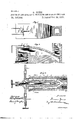
- Figure l is a plan
- Fig. 2 is a vertical section, of a conventional heating fur ⁇ nace with connections showing my apparatus for practicing my new process
- Fig. 3 is a longitudinal section of an injector device for withdrawing incandescent products of combustion from the furnace, for returning said products and for introducing steam and oil vapors to said furnace.
- A is an ordinary heating furnace, having a fire-chamber c, air-ports b, bridge-wall c, iron chamber d, charging-door e, throat f, neck g and stack h.
- an injector deviceconsisting of a shell or casing 1 having a branch conduit 2 leading to it from a point over the bridge-wall, as
- the casing which, with branch 2 constitutes a conduit for products of combustion
- the oil and steam conduits 3 and 4 are provided with concentric nozzles, as shown, and the steam conduit is provided with a conical valve 5 to regulate the amount of steam admitted to the furnace.
- the respective oil and steam pipes are provided with suitable valves or cocks, by means of which the flow of oil and steam may be regulated or shut off and the pipe for the hot products of combustion may also be provided with a valve for a similar purpose, if desired.
- the injector device extends through the top wall of the furnace, and the frontend or nozzle part is packed with fire cement, as shown at 10.
- the branch pipe 2 leads from a point over the bridge wall to the outer end of the casing.
- This pipe, as well as the shell l, being exposed to a very high degree of heat, may be lined with a core or tube of refractory material.
- the injector device may be attached to, or connected with, any part of the furnace desired, and will operate to carry out my process provided the branch pipeor products of combustion conduit leads from a part of the furnace containing incandescent products of combustion.
- the at mosphere drawn from the furnace through branch 2 and shell 1 consists of the products of combustion. ⁇
- These products in their highly-heatedcondition,passingthroughshell l, impart heat to the oil, and as said oil becomes heated, it imparts heat to the steam, and as the products of combustion, steam and oil are mingled at an incandescent heat, the temperature of the mixture is eq ualized, and decomposition of the carbon-dioxide and the Water vapors takes place and new combinations are formed in the furnace which are immediately ignited and consumed.
- a continuous process of producing and consuming gas is maintained by keeping up a supply of steam and oil.
Landscapes
- Engineering & Computer Science (AREA)
- Chemical & Material Sciences (AREA)
- Combustion & Propulsion (AREA)
- Mechanical Engineering (AREA)
- General Engineering & Computer Science (AREA)
Description
(No Model.)
@Jo-NBS. PROCESS 0F ANDAPPARATUSPOR MAKING AND BURNING FUEL GASf No. 507,500. PatentedOot. 24,1893.
vl NITED STATES PATENT OFFICE.
GOMER JONES, OF NEWARK, NEW JERSEY, ASSIGNOR OF ONE-HALE TO THE BROWN DEVELOPING COMPANY, OF NEW JERSEY.
PROCESS 0F AND APPARATUS FOR SPECIFICATION forming part of Letters Patent No. 507,500, dated October 24, 1893.
Application filed June 23,1893- To aZLwh/om/ Zt may concern:
Be it known thatl, GOMER JONES, a citizen of the United States, residing in the city of Newark, Essex county, New Jersey, have i11- vented certain new and usefullmprovements in the Process of and Apparatusfor Making and Burning Fuel-Gas and I do hereby declare that the following is a full, clear, and exact description of the same.
My invention relates to an improved process of making and burning fuel gas, and to apparatus for carrying the process into eect.
The invention involves a continuous process of making and burning fuel gas, and consists essentially in taking incandescent products of combustion from a furnace chamber into juxtaposition with hydrocarbon and water vapors Without mixing, imparting heat to said vapors from said products, afterward mixing and discharging said vapors and products to lsaid chamber, thereby decomposing the carbon-dioxide and water vapors, releasing the hydrogen, and uniting the'carbon and oxygen constituents in a new combination, as carbonmonoxide, and finally supplying air to support combustion.
The apparatus consists essentially in the combination of a furnace, an oil and steam conduit leading to said furnace, means for transferring incandescent products yof combustion from a part of the furnace which contains such products to a part adjacent to the steam and oil inlets and ports for supplying air to support combustion.
In the drawings forming a part of this specication, Figure l is a plan, and Fig. 2 is a vertical section, of a conventional heating fur` nace with connections showing my apparatus for practicing my new process. Fig. 3 is a longitudinal section of an injector device for withdrawing incandescent products of combustion from the furnace, for returning said products and for introducing steam and oil vapors to said furnace.
A is an ordinary heating furnace, having a fire-chamber c, air-ports b, bridge-wall c, iron chamber d, charging-door e, throat f, neck g and stack h. Connected with this furnace is an injector deviceconsisting of a shell or casing 1, having a branch conduit 2 leading to it from a point over the bridge-wall, as
Serial No. 478.1678. (No model.)
shown, or from any part of the furnace which contains incandescent products of combustion. Ooncentric with the casing is an oil conduit 3, and concentric with the oil conduit is a steam conduit 4, both conduits leading from suitable source of supply. The casing which, with branch 2, constitutes a conduit for products of combustion, and the oil and steam conduits 3 and 4 are provided with concentric nozzles, as shown, and the steam conduit is provided with a conical valve 5 to regulate the amount of steam admitted to the furnace. The respective oil and steam pipes are provided with suitable valves or cocks, by means of which the flow of oil and steam may be regulated or shut off and the pipe for the hot products of combustion may also be provided with a valve for a similar purpose, if desired. 6 is the cock or valve for the steam pipe, 7 the valve of the oilpipe, and 8 the valve in a cross-pipe 9 for connecting the steam and oil pipes. By this arrangementl am enabled to shut off the flow of oil and steam, or to switch the steam from its passage to that of the oil passage and thereby blow out and clean the oil conduit, as occasion may require.
The injector device extends through the top wall of the furnace, and the frontend or nozzle part is packed with fire cement, as shown at 10. The branch pipe 2 leads from a point over the bridge wall to the outer end of the casing. This pipe, as well as the shell l, being exposed to a very high degree of heat, may be lined with a core or tube of refractory material. Obviously, the injector device may be attached to, or connected with, any part of the furnace desired, and will operate to carry out my process provided the branch pipeor products of combustion conduit leads from a part of the furnace containing incandescent products of combustion.
Operation: Steam is first admitted through conduit 4, and escaping forcibly from its contracted nozzle, draws the oil through conduit 3 'and the atmosphere from the furnace over the bridge wall through branch Zand shell l.
When the injected vapors are ignited, the at mosphere drawn from the furnace through branch 2 and shell 1, consists of the products of combustion.` These products, in their highly-heatedcondition,passingthroughshell l, impart heat to the oil, and as said oil becomes heated, it imparts heat to the steam, and as the products of combustion, steam and oil are mingled at an incandescent heat, the temperature of the mixture is eq ualized, and decomposition of the carbon-dioxide and the Water vapors takes place and new combinations are formed in the furnace which are immediately ignited and consumed. Thus, a continuous process of producing and consuming gas is maintained by keeping up a supply of steam and oil.
I am aware that the products of combustion of carbonaceous fuel have been taken from a furnace chamber and injected into a gas retort, in connection with oil and steam,where carbonio acid is reduced and hydrogen released, and new combinations are formed in said retortwhich are conducted away for future use, but in such case the water and hydro-carbon vapors are not both heated by the hot products before being mixed, nor is the mixture introduced to the furnace chamber from which the products of combustion are drawn, as in my invention. I do not therefore claim broadly taking products of combustion from a furnace chamber and afterward mixing the same with steam and oil vapor to obtain the reactions herein named, but
What I do claim, and desire to secure by Letters Patent, is
l. The continuous process of burning fuel gas which consists in taking incandescent products of combustion from afurnace chamber into juxtaposition with hydro-carbon and water vapors without mixing any two of them, imparting heat to said vapors from the products, afterward mixing and discharging said products and vapors to said chamber, thereby decomposing the carbon-dioxide and water vapor, releasing the hydrogen and uniting the carbon and oxygen constituents in a new combination, as carbon monoxide, and finally burning the same, substantially as described.
2. In apparatus for making and burning fuel gas, the combination of a furnace, an oil and a steam conduit leading to said furnace, means for transferring incandescent products of combustion from a part of the furnace which contains such products to a part adjacent to the oil and steam inlets, and means for supplying air to support combustion.
3. In an apparatus for making and burning fuel gas, the combination of a combustion chamber, a central conduit leading from a steam generator, an oil conduit surrounding the steam conduit leading from an oil supply, and an outer conduit having a discharge nozzle common to all the conduits leading from a part of the combustion chamber containing products of approximately complete combustion back to said combustion chamber, substantially as described.
In testimonywhereof I aiiix my signature in the presence of two Witnesses.
GOMER JONES. Witnesses:
WM. M. STOGKBRIDGE, THEO. L. GATCHEL.
Publications (1)
| Publication Number | Publication Date |
|---|---|
| US507500A true US507500A (en) | 1893-10-24 |
Family
ID=2576333
Family Applications (1)
| Application Number | Title | Priority Date | Filing Date |
|---|---|---|---|
| US507500D Expired - Lifetime US507500A (en) | Process of and apparatus for making and burning fuel-gas |
Country Status (1)
| Country | Link |
|---|---|
| US (1) | US507500A (en) |
Cited By (1)
| Publication number | Priority date | Publication date | Assignee | Title |
|---|---|---|---|---|
| US2601242A (en) * | 1944-08-26 | 1952-06-24 | Claude A Bonvillian | Apparatus for the combustion of combustible and vaporizable substances |
-
0
- US US507500D patent/US507500A/en not_active Expired - Lifetime
Cited By (1)
| Publication number | Priority date | Publication date | Assignee | Title |
|---|---|---|---|---|
| US2601242A (en) * | 1944-08-26 | 1952-06-24 | Claude A Bonvillian | Apparatus for the combustion of combustible and vaporizable substances |
Similar Documents
| Publication | Publication Date | Title |
|---|---|---|
| US507500A (en) | Process of and apparatus for making and burning fuel-gas | |
| US2007200A (en) | Water gas carburetor | |
| US2563460A (en) | Appabatus foe continuously | |
| US816314A (en) | Process for making and burning fuel-gas. | |
| US564512A (en) | feheenbatgh | |
| US570382A (en) | Apparatus for manufacturing fuel-gas | |
| US365906A (en) | Apparatus for the manufacture of fuel and illuminating gas | |
| US977208A (en) | Method of combustion of oil and gas mixtures. | |
| US187734A (en) | Improvement in processes and apparatus for manufacturing gas | |
| US702418A (en) | Gas generating and burning furnace. | |
| US373468A (en) | Process of and apparatus for producing and consuming gaseous fuel | |
| US326161A (en) | selwyn | |
| US1804402A (en) | Enriching gas | |
| US398873A (en) | avert | |
| US483981A (en) | Process of and apparatus for the manufacture of gas | |
| US847733A (en) | Process of generating gas. | |
| US902970A (en) | Furnace. | |
| US550831A (en) | John raskins ladd | |
| US290930A (en) | Process of and apparatus for manufacturing fixed gas | |
| US231232A (en) | Island | |
| US240434A (en) | Island | |
| US525131A (en) | browne | |
| US1450338A (en) | Apparatus for producing gaseous fuel | |
| US418017A (en) | John hanlon | |
| US205143A (en) | Improvement in apparatus for burning hydrocarbons |