US5074717A - Clamped body replacement tool - Google Patents
Clamped body replacement tool Download PDFInfo
- Publication number
- US5074717A US5074717A US07/543,736 US54373690A US5074717A US 5074717 A US5074717 A US 5074717A US 54373690 A US54373690 A US 54373690A US 5074717 A US5074717 A US 5074717A
- Authority
- US
- United States
- Prior art keywords
- tool
- tubular member
- platens
- forcing
- cylinder
- Prior art date
- Legal status (The legal status is an assumption and is not a legal conclusion. Google has not performed a legal analysis and makes no representation as to the accuracy of the status listed.)
- Expired - Fee Related
Links
- 239000012530 fluid Substances 0.000 claims abstract description 31
- 230000008878 coupling Effects 0.000 claims description 9
- 238000010168 coupling process Methods 0.000 claims description 9
- 238000005859 coupling reaction Methods 0.000 claims description 9
- 229930195733 hydrocarbon Natural products 0.000 description 7
- 150000002430 hydrocarbons Chemical class 0.000 description 7
- 239000004215 Carbon black (E152) Substances 0.000 description 5
- 238000010276 construction Methods 0.000 description 3
- 238000000034 method Methods 0.000 description 3
- 238000010586 diagram Methods 0.000 description 2
- 238000006073 displacement reaction Methods 0.000 description 2
- 238000011065 in-situ storage Methods 0.000 description 2
- 238000000926 separation method Methods 0.000 description 2
- 238000013459 approach Methods 0.000 description 1
- 230000002939 deleterious effect Effects 0.000 description 1
- 230000001419 dependent effect Effects 0.000 description 1
- 230000000694 effects Effects 0.000 description 1
- 239000002360 explosive Substances 0.000 description 1
- 238000009434 installation Methods 0.000 description 1
- 230000014759 maintenance of location Effects 0.000 description 1
- 239000000463 material Substances 0.000 description 1
- 230000002285 radioactive effect Effects 0.000 description 1
- XLYOFNOQVPJJNP-UHFFFAOYSA-N water Substances O XLYOFNOQVPJJNP-UHFFFAOYSA-N 0.000 description 1
Images

Classifications
-
- E—FIXED CONSTRUCTIONS
- E21—EARTH OR ROCK DRILLING; MINING
- E21B—EARTH OR ROCK DRILLING; OBTAINING OIL, GAS, WATER, SOLUBLE OR MELTABLE MATERIALS OR A SLURRY OF MINERALS FROM WELLS
- E21B33/00—Sealing or packing boreholes or wells
- E21B33/02—Surface sealing or packing
- E21B33/03—Well heads; Setting-up thereof
- E21B33/035—Well heads; Setting-up thereof specially adapted for underwater installations
- E21B33/038—Connectors used on well heads, e.g. for connecting blow-out preventer and riser
-
- E—FIXED CONSTRUCTIONS
- E21—EARTH OR ROCK DRILLING; MINING
- E21B—EARTH OR ROCK DRILLING; OBTAINING OIL, GAS, WATER, SOLUBLE OR MELTABLE MATERIALS OR A SLURRY OF MINERALS FROM WELLS
- E21B41/00—Equipment or details not covered by groups E21B15/00 - E21B40/00
- E21B41/04—Manipulators for underwater operations, e.g. temporarily connected to well heads
Definitions
- This invention relates to tools suitable for use in replacing a body held clamped between two other members and particularly, but not exclusively, to tools for performing such an operation remotely on subsea hydrocarbon producing structures.
- valves It is known in subsea hydrocarbon-producing well structures to provide a valve with a body having in-line port faces designed to slide between two flange-like platens at facing ends of spaced axially aligned ducted members, the valve being held in situ by being clamped between the platens by pressure exerted on them by threaded members extending between the ducted members and held in tension or by other clamping means.
- Such a valve body is dimensioned and the clamping members disposed in relation thereto whereby the valve body can be removed from between the platens and replaced without dismantling the structure or clamping means by applying a force to overcome the clamping pressure on the valve body.
- valve body may be used equally with a body not comprising part of a valve.
- valve or other body which has an axial extension at the body or platen faces which locate with corresponding recesses in the other faces, requiring the platens to be displaced or spread by the amount of this projection, the clamping means being constructed to permit such displacements.
- a replacement tool for a body having opposite faces held clamped between two facing platens which extend laterally of both sides of the body comprises a hollow open ended tubular member the internal cross section of which is adapted to permit passage of the body therethrough, a pair of support arms extending axially of the tubular member from opposite sides thereof each supporting at the extremity thereof an extensible force exerting arrangement extensible in a direction substantially perpendicular to the axis of the member and the plane through the member containing the two arms, said arms and force exerting arrangements being spaced from each other by a distance greater than the width of the clamped body so as to be positioned astride the clamped body with the force exerting arrangements disposed between the platens, and force producing means operable to couple a source of extension force to the arrangements such that the force exerted by the arrangements in extending against the facing platens is sufficient to overcome the force of the platen clamping means and permit the body to be removed from between the platens through the tubular member and vice versa.
- FIGS. 1 and 2 are elevation and plan views respectively of a portion of a subsea hydrocarbon producing well showing the disposition of certain valve members including a sub-sea wing valve held in position solely by clamping pressure between two surrounding members and the means of applying the clamping pressure,
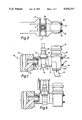
- FIG. 3 is an end view of a fluid operated tool according to the present invention
- FIG. 4 is a sectional elevation through the tool along the line 4--4 of FIG. 3,
- FIG. 5 is a sectional elevation through the tool taken along the line 5--5 of FIG. 3,
- FIG. 6 is an elevation view of the well portion and clamped using valve of FIG. 1 illustrating the disposition of the replacement tool in relation thereto for operation
- FIG. 7 is a schematic hydraulic circuit diagram for operation and control of the tool.
- a subsea hydrocarbon producing well 10 comprises a valve block 11 having a substantially vertical bore 12 through which hydrocarbons rise from a well (not show:).
- the vertical bore 12 is joined by bore 13 to a substantially horizontal bore 14 in duct member 15 secured to the block 11.
- the horizontal bore extends through a controllable wing valve 16 and a further duct member 17 into a choke valve 18, from which the hydrocarbons emerge in a downward direction into a flowline 19 by which they are removed from the vicinity of the well.
- wing valve 16 and choke valve 18 are well known and require no detailed description. Their disposition in the manner described and illustrated facilitates their removal and replacement by a suspended lifting rope depending from a surface or sub-sea crane.
- the working part 18' of the choke valve is removable from above without disturbing housing 18" and the housing 18", and duct member 17 are mounted in relation to duct member 15 by a number, say four, of tie rods 20-23.
- the wing valve 16 has a body portion 25 with inlet and outlet ports at opposite faces thereof and a stem position 26 including control, actuation and other functional means associated with valve operation extending in a direction laterally of the flow path through the valve body between the ports, in this case vertically to facilitate lifting and lowering of the complete valve.
- the width W of the wing valve body 25 in a direction perpendicular to the flow passage between ports and to the axis of stem portion 26 is no greater than the gap between adjacent upper tie rods 20 and 24 and length L between ports defines the separation of the duct members 15 and 17 which end in platens 27, 28 respectively, facing each other and extending each side of the valve body.
- valve body between the facing platens nuts 29 may be tightened on the tie rods and the valve body clamped between the facing platens, the clamping force exerted by the platens due to tension in the tie rods being the sole mean of retention.
- ROV's Submersible remotely operated vehicles
- a tool 30 is provided to facilitate replacement of the wing valve 16 remotely, that is, using only a ROV and/or lifting or lowering device in conjunction with the tool.
- the tool 30 comprises a hollow open ended tubular member 31, conveniently comprising a right circular cylinder, having longitudinal axis 32 and a diameter great enough to permit the passage of the valve therethrough.
- the stem portion 26 not forming the valve body 25 may in fact have one or more dimensions greater than the valve body and it is the overall dimensions of the valve, not just the valve body which are accommodated by the tubular member.
- a pair of support arms 33, 34 extend axially of the tubular member from opposite sides thereof, the arms being formed of bars attached to the tubular member at diametrically opposite points 33' and 34' along the outer tubular walls so that they are separated from each other by greater than the diameter of the tubular member.
- the bars are of greater dimension in the direction radially outwards of the tubular member than in the orthogonal direction and are essentially coplanar.
- the support arms 33 and 34 carry at the extremities thereof extensible force exerting arrangements 35, 36 respectively comprising fluid pressure activated forcing piston and cylinder.
- Each forcing cylinder contains at least one axially reciprocable piston, shown ghosted at 37 preferably adapted to retract flush with the end of the cylinder.
- the forcing cylinder 36 may contain a second axially reciprocable piston 37' aligned with the piston 37 and displaceable oppositely with respect thereto.
- the length of cylinder and retracted piston combination is arranged to be slightly less than the separation of the facing platens 27, 28 of the clamped valve structure.
- the forcing cylinder 36 is supplied with pressurised actuating fluid, conveniently hydraulic fluid, by fluid coupling means comprising pipework (not shown) from fluid pressure intensifier 38 carried along the outside of the tubular member which in turn receives fluid at a lower pressure at tool connection 39 from an external source such as the hydraulic circuit of an ROV.
- fluid coupling means comprising pipework (not shown) from fluid pressure intensifier 38 carried along the outside of the tubular member which in turn receives fluid at a lower pressure at tool connection 39 from an external source such as the hydraulic circuit of an ROV.
- ROV's operate on relatively low hydraulic pressures, of the order of 200 Bar and the use of a known type of intensifier providing say, 7 times pressure magnification enables a fluid pressure of some 1400 Bar to be made available to the forcing cylinder 36.
- the forcing cylinder 35 with its piston 40 is identical with the piston and cylinder arrangement 36/37 and operates in parallel therewith upon the coupling thereof to the external fluid source.
- the forcing cylinders are disposed with the reciprocation axis of their pistons parallel to each other and orthogonal to both the longitudinal axis 32 of the tubular member and to the diametrical plane containing the support arms 33 and 34.
- the widths of support arm 33 and 34 are conveniently substantially equal to the outside diameters of the respectively forcing cylinder 35 and 36 so as to provide uniform support, and to hold the cylinders separated from each other by no less than the internal diameter of the tubular member.
- the tool 30 also includes handling means 41 in the form of a profiled peg adapted on the inside wall of the tubular member to cooperate with handling means of an ROV whereby the ROV can transport the tool, orientate it and dispose it in relation to the structure containing the wing valve.
- handling means 41 in the form of a profiled peg adapted on the inside wall of the tubular member to cooperate with handling means of an ROV whereby the ROV can transport the tool, orientate it and dispose it in relation to the structure containing the wing valve.
- To use the tool it is brought to the structure and the tubular member is passed over the valve stem portion 26 and orientated about the stem portion so that the forcing cylinders and their support arms extend into the space between the facing platens 27, 28 astride the valve body 25 with the forcing pistons 37 (37'), 40 (40') facing one (or both) platens.
- the ROV which positions the tool provides hydraulic fluid from its own circuit to the coupling means 39 which forces the facing pistons from their cylinders to abut one platen and react with the cylinder or second piston against the other platen, overcoming the clamping force of the tensioned tie rods.
- each piston cylinder combination may be provided with limiting means which comprises either a physical stop to limit the piston travel or a pressure release means to limit the spreading force applied to the platens.
- the wing valve is removed by way of the tubular member, which is now securely fixed with respect to the structure by the forcing piston and cylinder arrangements, which member constrains the direction of removal of the valve from the structure so as to avoid any damaging impacts between relatively moving parts or between the removed valve and the vulnerable coupling hydraulic of the tool.
- a replacement valve is positioned by lowering it into the tubular member such that it, or at least portion 25, passes therethrough and locates between the facing platens and tie rods.
- the fluid pressure is thereafter reduced, permitting the original tension in the tie rods 20-23 to draw the facing platens towards each other and re-establish clamping pressure on the wing valve body, and the tool is removed from the structure by lifting the tubular body over the stem portion 26 of the wing valve.
- the ROV may decouple the handling means to give more room for manipulation of the valve and its replacement.
- the hydraulic coupling may be maintained, with the connection to the ROV being by a flexible base or the like which permits the ROV to stand off during valve replacement or to participate in the valve replacement with the handling means recently decoupled from the tool.
- the fluid coupling means may contain control means, a schematic hydraulic circuit diagram of which is shown in FIG. 7, including a control valve 42 operable to lock the fluid in the forcing piston and cylinder arrangements to latch them in the extended piston. If such a control valve 42 is carried by the tool the ROV may be decoupled completely from the tool for the valve replacement operation, although both the fluid supply and control connections are required when coupled. Such a latching control arrangement may be provided on the ROV and latching be likewise effected, even though the ROV can no longer be decoupled from the fluid circuit.
- the tubular member may be provided with internal surface constructions such as 31' which cooperate with existing or specially provided surface structures of the stem portion 26 of the valve. Such a cooperating arrangement may also be used to align the orientation of the replacement valve with respect to the space between the plates.
- each of the forcing cylinders 35 and 36 is provided on the side away from its support arm, that is, the leading edge of the tool as it approaches the platen, with a guide projection 43 tapering to a point in the plane of piston and cylinder extension.
- tubular member 31 when tubular member 31 is located over the valve stem to avoid any deleterious effects of the extremity of the valve stem abutting the end of a badly aligned tubular member the end of the tubular member may be provided with a guide funnel 44. Similarly, to assist a replacement valve pass through the installed body member the other end may be provided with a guide funnel 45.
- the tool may be used in replacement of a clamped body which is other than a valve and a body which does not have a laterally extending, or upstanding, equivalent of the valve stem portion 26 illustrated.
- the tool construction and operation is still as described, with the guide projections 43 on forcing cylinder and guide funnel 45 assuming greater importance in positioning the tool and ensuring the unclamped body is passed into, and through, the tubular member without problem.
- the tool has been described as operated by, and in association with, a submersible ROV it will be understood that the tool may be installed and removed by other means, such as by lowering on a suspended line in the vertical direction, and may be used by a diver, where one is at work, to simplify and speed up a body replacement operation.
- the shape of the tubular member is not restricted to being circular cross section, nor are the support arms necessarily connected to diametrically opposite wall portions nor of the shape and disposition shown, provided they support the forcing cylinders astride the clamped body and permit its removal through the tubular member.
- the support arms may comprise integral extended portions of the tubular member.
- a tool as described may be used with a clamped body which is not a simple sliding fit between the clamping platens but one which is located between them by small cooperating axial projections and recessed in the body and platen faces. Replacement of such a body requires not only that the clamping pressure of the clamping means, such as the tensioned tie rods, is equalled but is overcome and the platens moved apart or spread by the extent of such body-locating projections.
- the tool is not dependent on the form of clamping applied to the platen surfaces and requires only that the forcing cylinders be slidable between and from the facing platens astride the body to permit its displacement by way of the tubular member.
- the tool hitherto described overcomes the clamping force on the body to be replaced by means of extensible force exerting arrangements comprising fluid pressure actuated piston and cylinder arrangements.
- the forces involved are such as to practicably require a hydraulic fluid, if supplied by an ROV, to be intensified.
- the intensifier may not be required.
- the fluid is available from a source at the required end pressure the intensifier may be omitted.
- pressured fluid other than hydraulic fluid may be used where appropriate, such as a gas in a pneumatic circuit.
- a housing corresponding to the forcing cylinder described above may house an extensible piston-like member displaced by other means, such as being formed as a nut on a rotating lead screw or as an axially displaced rotating screw jack, the extension force producing means then comprising fluid turbine or electric motor drive.
- the tool may be used in situations other than subsea, which are hostile and require remote handling techniques, such as in explosive or radioactive environments.
Landscapes
- Life Sciences & Earth Sciences (AREA)
- Engineering & Computer Science (AREA)
- Geology (AREA)
- Mining & Mineral Resources (AREA)
- Physics & Mathematics (AREA)
- Environmental & Geological Engineering (AREA)
- Fluid Mechanics (AREA)
- General Life Sciences & Earth Sciences (AREA)
- Geochemistry & Mineralogy (AREA)
- Earth Drilling (AREA)
Abstract
Description
Claims (13)
Applications Claiming Priority (4)
| Application Number | Priority Date | Filing Date | Title |
|---|---|---|---|
| GB888802737A GB8802737D0 (en) | 1988-02-06 | 1988-02-06 | Clamped body replacement tool |
| GB8802737 | 1988-02-06 | ||
| GB8819910A GB2217641A (en) | 1988-02-06 | 1988-08-22 | Clamped body replacement tool |
| GB8819910 | 1988-08-22 |
Publications (1)
| Publication Number | Publication Date |
|---|---|
| US5074717A true US5074717A (en) | 1991-12-24 |
Family
ID=26293443
Family Applications (1)
| Application Number | Title | Priority Date | Filing Date |
|---|---|---|---|
| US07/543,736 Expired - Fee Related US5074717A (en) | 1988-02-06 | 1989-02-06 | Clamped body replacement tool |
Country Status (5)
| Country | Link |
|---|---|
| US (1) | US5074717A (en) |
| EP (1) | EP0397771A1 (en) |
| BR (1) | BR8907229A (en) |
| NO (1) | NO903435L (en) |
| WO (1) | WO1989007191A1 (en) |
Cited By (2)
| Publication number | Priority date | Publication date | Assignee | Title |
|---|---|---|---|---|
| US5273376A (en) * | 1992-02-10 | 1993-12-28 | Shell Offshore Inc. | Back-up connector release tool |
| US5340237A (en) * | 1991-11-05 | 1994-08-23 | Petroleo Brasileiro S.A. | Guide-post interchangeability mechanism operated by remotely controlled vehicle |
Families Citing this family (2)
| Publication number | Priority date | Publication date | Assignee | Title |
|---|---|---|---|---|
| NO169059C (en) * | 1990-03-19 | 1992-05-06 | Holta Leif | TOOL USE DEVICE FOR REPLACEMENT OF AN INSTRUMENTS IN THEIR FUNCTIONAL POSITION ARE ENTERED BY AN INSTRUMENT HOUSE WHICH MAY BE CONNECTED IN A FLUID CONTROL, USE AND PROCEDURE FOR REPLACING THE INSTRUMENTS |
| US5255745A (en) * | 1992-06-18 | 1993-10-26 | Cooper Industries, Inc. | Remotely operable horizontal connection apparatus and method |
Citations (6)
| Publication number | Priority date | Publication date | Assignee | Title |
|---|---|---|---|---|
| US3481396A (en) * | 1968-06-27 | 1969-12-02 | Cameron Iron Works Inc | Connector for underwater pipelines |
| US3675713A (en) * | 1970-03-30 | 1972-07-11 | Regan Forge & Eng Co | Method and apparatus for separating subsea well conduit couplings from a remote floating vessel |
| US4139322A (en) * | 1976-06-11 | 1979-02-13 | Entreprise d'Equipments Mecaniques et Hydrauliques E.M.H. | Equipment for removing and refitting resilient packing in a cardan joint |
| US4382717A (en) * | 1978-12-28 | 1983-05-10 | Smith International, Inc. | Connection of underwater lines |
| EP0085280A1 (en) * | 1982-01-28 | 1983-08-10 | Grove Valve And Regulator Company | Line removable valve structure with pipeline support means |
| US4452312A (en) * | 1981-02-23 | 1984-06-05 | Alteliers et Chantiers de Chantiers de Bretagne-ACB | Modular undersea oil production plant |
-
1989
- 1989-02-06 EP EP89902272A patent/EP0397771A1/en not_active Withdrawn
- 1989-02-06 WO PCT/GB1989/000101 patent/WO1989007191A1/en not_active Application Discontinuation
- 1989-02-06 BR BR898907229A patent/BR8907229A/en unknown
- 1989-02-06 US US07/543,736 patent/US5074717A/en not_active Expired - Fee Related
-
1990
- 1990-08-06 NO NO90903435A patent/NO903435L/en unknown
Patent Citations (6)
| Publication number | Priority date | Publication date | Assignee | Title |
|---|---|---|---|---|
| US3481396A (en) * | 1968-06-27 | 1969-12-02 | Cameron Iron Works Inc | Connector for underwater pipelines |
| US3675713A (en) * | 1970-03-30 | 1972-07-11 | Regan Forge & Eng Co | Method and apparatus for separating subsea well conduit couplings from a remote floating vessel |
| US4139322A (en) * | 1976-06-11 | 1979-02-13 | Entreprise d'Equipments Mecaniques et Hydrauliques E.M.H. | Equipment for removing and refitting resilient packing in a cardan joint |
| US4382717A (en) * | 1978-12-28 | 1983-05-10 | Smith International, Inc. | Connection of underwater lines |
| US4452312A (en) * | 1981-02-23 | 1984-06-05 | Alteliers et Chantiers de Chantiers de Bretagne-ACB | Modular undersea oil production plant |
| EP0085280A1 (en) * | 1982-01-28 | 1983-08-10 | Grove Valve And Regulator Company | Line removable valve structure with pipeline support means |
Cited By (2)
| Publication number | Priority date | Publication date | Assignee | Title |
|---|---|---|---|---|
| US5340237A (en) * | 1991-11-05 | 1994-08-23 | Petroleo Brasileiro S.A. | Guide-post interchangeability mechanism operated by remotely controlled vehicle |
| US5273376A (en) * | 1992-02-10 | 1993-12-28 | Shell Offshore Inc. | Back-up connector release tool |
Also Published As
| Publication number | Publication date |
|---|---|
| WO1989007191A1 (en) | 1989-08-10 |
| NO903435D0 (en) | 1990-08-06 |
| NO903435L (en) | 1990-08-06 |
| EP0397771A1 (en) | 1990-11-22 |
| BR8907229A (en) | 1991-03-05 |
Similar Documents
| Publication | Publication Date | Title |
|---|---|---|
| US4053973A (en) | Pipe-handling apparatus | |
| US6439807B1 (en) | Method and apparatus for underwater connection of pipe pieces and bolt therefor | |
| US3796418A (en) | Hydraulic pipe tong apparatus | |
| US8702349B2 (en) | Pipe bursting apparatus | |
| US6860343B2 (en) | Drill rod holder | |
| US6582158B1 (en) | Device and method for transferring vibrating movement to rigid pipe with pipe clamp for vibrator rammer block | |
| DE1934884C3 (en) | Device for connecting two underwater pipelines | |
| US5074717A (en) | Clamped body replacement tool | |
| KR101580781B1 (en) | Method and arrangement for attachment and/or disassembly/assembly of a tunnel thruster | |
| US4669915A (en) | Manipulator apparatus with flexible membrane for gripping submerged objects | |
| US4050955A (en) | Method and apparatus for launching pipeline clearing spheres | |
| GB2217641A (en) | Clamped body replacement tool | |
| US4067200A (en) | Device and method for installing ducts in holes produced by soil piercing tool | |
| US3038546A (en) | Horizontal earth boring apparatus | |
| US4492274A (en) | Light weight underground pipe or cable installing device | |
| RU2109353C1 (en) | Method and device for cutting nuclear plant components into fragments by spalling | |
| US2682102A (en) | Drill pipe protector apparatus | |
| CN220551087U (en) | Tube drawing device and system | |
| US5181413A (en) | Pipe collapsing attachment | |
| CN213562229U (en) | Hydraulic clamp for assembling auxiliary hydraulic valve | |
| EP0624712B1 (en) | Submarine wellhead anchor | |
| US10655295B2 (en) | Clamping adapter and methods for sonic pile driving | |
| JPH0646170Y2 (en) | Cable pulling device | |
| GB2302076A (en) | Tube gripping and translating apparatus | |
| EP1027529B1 (en) | Apparatus for bending and cutting cable in rock bolting equipment |
Legal Events
| Date | Code | Title | Description |
|---|---|---|---|
| AS | Assignment |
Owner name: CAMERON OFFSHORE ENGINEERING LIMITED, PREMIER HOUS Free format text: ASSIGNMENT OF ASSIGNORS INTEREST.;ASSIGNORS:HOPE, RODNEY C.;LAWSON, JOHN E.;HATTON, STEPHEN A.;REEL/FRAME:005497/0243 Effective date: 19900911 Owner name: CAMERON OFFSHORE ENGINEERING LIMITED, PREMIER HOUS Free format text: ASSIGNMENT OF ASSIGNORS INTEREST.;ASSIGNOR:LAWSON, JOHN E.;REEL/FRAME:005497/0246 Effective date: 19900827 Owner name: MOBIL OIL CORPORATION, 150 EAST 42ND ST., NEW YORK Free format text: ASSIGNMENT OF ASSIGNORS INTEREST.;ASSIGNORS:HOPE, RODNEY C.;LAWSON, JOHN E.;HATTON, STEPHEN A.;REEL/FRAME:005497/0243 Effective date: 19900911 Owner name: FSSL LIMITED, CASTLE INDUSTRIAL ESTATE, ELLON, ABE Free format text: ASSIGNMENT OF ASSIGNORS INTEREST.;ASSIGNOR:LAWSON, JOHN E.;REEL/FRAME:005497/0246 Effective date: 19900827 Owner name: FSSL LIMITED, CASTLE INDUSTRIAL ESTATE, ELLON, ABE Free format text: ASSIGNMENT OF ASSIGNORS INTEREST.;ASSIGNORS:HOPE, RODNEY C.;LAWSON, JOHN E.;HATTON, STEPHEN A.;REEL/FRAME:005497/0243 Effective date: 19900911 Owner name: MOBIL OIL CORPORATION, 150 EAST 42ND STREET, NEW Y Free format text: ASSIGNMENT OF ASSIGNORS INTEREST.;ASSIGNOR:LAWSON, JOHN E.;REEL/FRAME:005497/0246 Effective date: 19900827 |
|
| FPAY | Fee payment |
Year of fee payment: 4 |
|
| REMI | Maintenance fee reminder mailed | ||
| LAPS | Lapse for failure to pay maintenance fees | ||
| FP | Lapsed due to failure to pay maintenance fee |
Effective date: 19991224 |
|
| STCH | Information on status: patent discontinuation |
Free format text: PATENT EXPIRED DUE TO NONPAYMENT OF MAINTENANCE FEES UNDER 37 CFR 1.362 |