US5073738A - Direct current motor having a retaining device for holding magnets - Google Patents
Direct current motor having a retaining device for holding magnets Download PDFInfo
- Publication number
- US5073738A US5073738A US07/634,897 US63489790A US5073738A US 5073738 A US5073738 A US 5073738A US 63489790 A US63489790 A US 63489790A US 5073738 A US5073738 A US 5073738A
- Authority
- US
- United States
- Prior art keywords
- magnets
- housing
- rings
- direct current
- current motor
- Prior art date
- Legal status (The legal status is an assumption and is not a legal conclusion. Google has not performed a legal analysis and makes no representation as to the accuracy of the status listed.)
- Expired - Fee Related
Links
- 230000000717 retained effect Effects 0.000 claims abstract description 12
- 239000000853 adhesive Substances 0.000 claims abstract description 6
- 230000001070 adhesive effect Effects 0.000 claims abstract description 6
- 239000000463 material Substances 0.000 claims abstract description 6
- 238000010276 construction Methods 0.000 description 1
Images
Classifications
-
- H—ELECTRICITY
- H02—GENERATION; CONVERSION OR DISTRIBUTION OF ELECTRIC POWER
- H02K—DYNAMO-ELECTRIC MACHINES
- H02K1/00—Details of the magnetic circuit
- H02K1/06—Details of the magnetic circuit characterised by the shape, form or construction
- H02K1/12—Stationary parts of the magnetic circuit
- H02K1/17—Stator cores with permanent magnets
Definitions
- the present invention relates to a direct current motor, and more particularly to a direct current motor having a retaining device for holding magnets.
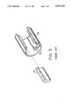
- a direct current motor usually has two, four or six magnets 92 received in a housing 90.
- the magnets 92 are generally adhered within the housing 90 by adhesive materials. During operation, heat will be generated within the motor and the temperature within the motor will be increased so that the quality and the property of the adhesive materials will be changed and so that the magnets can not be stably retained in place which may cause the failure of the direct current motors.
- the present invention has arisen to mitigate and/or obviate the afore-described disadvantages of the conventional direct current motors.
- the primary objective of the present invention is to provide a direct current motor which has a retaining device for holding magnets so that the magnets can be stably retained in place.
- a direct current motor which includes a cylindrically shaped housing.
- Four magnets are received within the housing and contact the inner surface of the housing.
- a pair of rings are force-fitted within the end portions of the housing and are coupled together by bolts.
- Each of the rings has an annular flange extended inward. The magnets are retained between the annular flanges of the rings so that the magnets can be stably retained in place by the rings without any adhesive material.
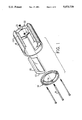
- FIG. 1 is an exploded view of a direct current motor in accordance with the present invention
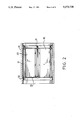
- FIG. 2 is a cross sectional view of the motor
- FIG. 3 is an exploded view of a conventional direct current motor.
- a direct current motor in accordance with the present invention comprises generally a housing 10, four magnets 20 received within the housing 10, and a pair of rings 30 for stably holding the magnets 20 within the housing 10.
- the housing 10 is substantially cylindrical shaped.
- the magnets 20 have a suitable curvature so that the magnets 20 closely contact the inner surface of the housing 10.
- the retaining device includes a pair of rings 30 each having an inwardly extended annular flange 32.
- the rings 30 are force-fitted in the end portions of the housing 10.
- the annular flanges 32 are coupled together by bolts 31 so that the magnets 20 can be stably retained between the rings 30.
- Four recesses 33 are formed in an inner surface of each of the annular flanges 32.
- the shape of each of the recesses 33 is similar to that of the end surface 22 of the magnet 20 so that the magnets 20 can further be stably retained by the rings 30.
- the magnets 20 of the direct current motor in accordance with the present invention can be stably retained within the housing 10 by the rings 30 so that the magnets can be stably retained in place without any adhesive material.
Landscapes
- Engineering & Computer Science (AREA)
- Power Engineering (AREA)
- Permanent Field Magnets Of Synchronous Machinery (AREA)
- Dc Machiner (AREA)
Abstract
A direct current motor includes a housing which is cylindrically shaped. Four magnets are received within the housing and contact the inner surface of the housing. A pair of rings are force-fitted within the end portions of the housing and are coupled together by bolts. Each of the rings has an annular flange extended inward. The magnets are retained between the annular flanges of the rings so that the magnets can be stably retained in place by the rings without any adhesive material.
Description
The present invention relates to a direct current motor, and more particularly to a direct current motor having a retaining device for holding magnets.
As shown in FIG. 3, a direct current motor usually has two, four or six magnets 92 received in a housing 90. The magnets 92 are generally adhered within the housing 90 by adhesive materials. During operation, heat will be generated within the motor and the temperature within the motor will be increased so that the quality and the property of the adhesive materials will be changed and so that the magnets can not be stably retained in place which may cause the failure of the direct current motors.
The present invention has arisen to mitigate and/or obviate the afore-described disadvantages of the conventional direct current motors.
The primary objective of the present invention is to provide a direct current motor which has a retaining device for holding magnets so that the magnets can be stably retained in place.
In accordance with one aspect of the invention, there is provided a direct current motor which includes a cylindrically shaped housing. Four magnets are received within the housing and contact the inner surface of the housing. A pair of rings are force-fitted within the end portions of the housing and are coupled together by bolts. Each of the rings has an annular flange extended inward. The magnets are retained between the annular flanges of the rings so that the magnets can be stably retained in place by the rings without any adhesive material.
Further objectives and advantages of the present invention will become apparent from a careful reading of the detailed description provided hereinbelow, with appropriate reference to the accompanying drawings.
FIG. 1 is an exploded view of a direct current motor in accordance with the present invention;
FIG. 2 is a cross sectional view of the motor; and
FIG. 3 is an exploded view of a conventional direct current motor.
Referring to FIGS. 1 and 2, a direct current motor in accordance with the present invention comprises generally a housing 10, four magnets 20 received within the housing 10, and a pair of rings 30 for stably holding the magnets 20 within the housing 10.
The housing 10 is substantially cylindrical shaped. The magnets 20 have a suitable curvature so that the magnets 20 closely contact the inner surface of the housing 10. The retaining device includes a pair of rings 30 each having an inwardly extended annular flange 32. The rings 30 are force-fitted in the end portions of the housing 10. The annular flanges 32 are coupled together by bolts 31 so that the magnets 20 can be stably retained between the rings 30. Four recesses 33 are formed in an inner surface of each of the annular flanges 32. The shape of each of the recesses 33 is similar to that of the end surface 22 of the magnet 20 so that the magnets 20 can further be stably retained by the rings 30.
Accordingly, the magnets 20 of the direct current motor in accordance with the present invention can be stably retained within the housing 10 by the rings 30 so that the magnets can be stably retained in place without any adhesive material.
Although this invention has been described with a certain degree of particularity, it is to be understood that the present disclosure has been made by way of example only and that numerous changes in the detailed construction and the combination and arrangement of parts may be resorted to without departing from the spirit and scope of the invention as hereinafter claimed.
Claims (1)
1. A direct current motor comprising a housing which is cylindrically shaped, at least two magnets being received within said housing and contacting an inner surface of said housing, a pair of rings being force-fitted within end portions of said housing and being coupled together by bolts, each of said rings having an annular flange extended inward therefrom, said magnets being retained and coupled between said annular flanges of said rings, each of said annular flanges having at least two recesses formed in an inner surface thereof, each of said recesses having a shape similar to that of an end portion of each of said magnets so that said end portions of said magnets can be engaged within said recesses respectively and so that said magnets can be stably retained in place by said rings without any adhesive material.
Priority Applications (1)
| Application Number | Priority Date | Filing Date | Title |
|---|---|---|---|
| US07/634,897 US5073738A (en) | 1990-12-27 | 1990-12-27 | Direct current motor having a retaining device for holding magnets |
Applications Claiming Priority (1)
| Application Number | Priority Date | Filing Date | Title |
|---|---|---|---|
| US07/634,897 US5073738A (en) | 1990-12-27 | 1990-12-27 | Direct current motor having a retaining device for holding magnets |
Publications (1)
| Publication Number | Publication Date |
|---|---|
| US5073738A true US5073738A (en) | 1991-12-17 |
Family
ID=24545594
Family Applications (1)
| Application Number | Title | Priority Date | Filing Date |
|---|---|---|---|
| US07/634,897 Expired - Fee Related US5073738A (en) | 1990-12-27 | 1990-12-27 | Direct current motor having a retaining device for holding magnets |
Country Status (1)
| Country | Link |
|---|---|
| US (1) | US5073738A (en) |
Cited By (11)
| Publication number | Priority date | Publication date | Assignee | Title |
|---|---|---|---|---|
| US5268607A (en) * | 1992-09-09 | 1993-12-07 | Webster Plastics | Molded resin motor housing |
| US5430338A (en) * | 1994-02-14 | 1995-07-04 | Mcmillan Electric Company | Motor casing and method of manufacture |
| US5475276A (en) * | 1994-10-05 | 1995-12-12 | Nippondenso Co., Ltd. | Electric rotating machine |
| WO1997005687A1 (en) * | 1995-07-28 | 1997-02-13 | Ryobi North America, Inc. | Method for securing magnets to a permanent magnet motor shell and a motor made therefrom |
| US5861694A (en) * | 1996-06-28 | 1999-01-19 | Ryobi North America Inc. | Field retaining mechanism for a permanent magnet D.C. motor |
| US6087748A (en) * | 1996-01-16 | 2000-07-11 | Donner; Michael | Magnetic pole rotor for revolution counting |
| JP2001275303A (en) * | 2000-03-27 | 2001-10-05 | Calsonic Kansei Corp | Motor for driving blower fan |
| US6339274B1 (en) * | 1997-10-24 | 2002-01-15 | Empresa Brasileira De Compressores S.A.-Embraco | Electric motor rotor with permanent magnets |
| US20040150281A1 (en) * | 2001-06-14 | 2004-08-05 | Jukka Malmberg | Permanent magnet element and electric machine |
| US20050066515A1 (en) * | 2003-09-29 | 2005-03-31 | Peresada Gary L. | Method and apparatus for mounting a plurality of magnet segments on a back ring |
| US20060238054A1 (en) * | 2005-04-26 | 2006-10-26 | Bison Gear & Engineering Corp. | Magnet retainer clip for permanent magnet electric motors |
Citations (5)
| Publication number | Priority date | Publication date | Assignee | Title |
|---|---|---|---|---|
| US3083310A (en) * | 1960-03-11 | 1963-03-26 | Controls Co Of America | Electric motor having a permanent magnet stator |
| US3489937A (en) * | 1967-12-18 | 1970-01-13 | Gen Electric | Motor construction |
| US4445060A (en) * | 1980-12-20 | 1984-04-24 | Robert Bosch Gmbh | Electric starter motor with holder for permanent magnets |
| US4851727A (en) * | 1986-04-09 | 1989-07-25 | Mitsubishi Denki Kabushiki Kaisha | Permanent magnet type electric motor |
| US4873461A (en) * | 1988-05-13 | 1989-10-10 | Stryker Corporation | Electric motor sterilizable surgical power tool |
-
1990
- 1990-12-27 US US07/634,897 patent/US5073738A/en not_active Expired - Fee Related
Patent Citations (5)
| Publication number | Priority date | Publication date | Assignee | Title |
|---|---|---|---|---|
| US3083310A (en) * | 1960-03-11 | 1963-03-26 | Controls Co Of America | Electric motor having a permanent magnet stator |
| US3489937A (en) * | 1967-12-18 | 1970-01-13 | Gen Electric | Motor construction |
| US4445060A (en) * | 1980-12-20 | 1984-04-24 | Robert Bosch Gmbh | Electric starter motor with holder for permanent magnets |
| US4851727A (en) * | 1986-04-09 | 1989-07-25 | Mitsubishi Denki Kabushiki Kaisha | Permanent magnet type electric motor |
| US4873461A (en) * | 1988-05-13 | 1989-10-10 | Stryker Corporation | Electric motor sterilizable surgical power tool |
Cited By (16)
| Publication number | Priority date | Publication date | Assignee | Title |
|---|---|---|---|---|
| US5584114A (en) * | 1992-09-09 | 1996-12-17 | Webster Plastics | Method of making molded resin motor housing |
| US5268607A (en) * | 1992-09-09 | 1993-12-07 | Webster Plastics | Molded resin motor housing |
| US5430338A (en) * | 1994-02-14 | 1995-07-04 | Mcmillan Electric Company | Motor casing and method of manufacture |
| US5475276A (en) * | 1994-10-05 | 1995-12-12 | Nippondenso Co., Ltd. | Electric rotating machine |
| WO1997005687A1 (en) * | 1995-07-28 | 1997-02-13 | Ryobi North America, Inc. | Method for securing magnets to a permanent magnet motor shell and a motor made therefrom |
| US5874794A (en) * | 1995-07-28 | 1999-02-23 | Ryobi North America, Inc. | Method for securing magnets to a permanent magnet motor shell and a motor made therefrom |
| US6087748A (en) * | 1996-01-16 | 2000-07-11 | Donner; Michael | Magnetic pole rotor for revolution counting |
| US5861694A (en) * | 1996-06-28 | 1999-01-19 | Ryobi North America Inc. | Field retaining mechanism for a permanent magnet D.C. motor |
| US6339274B1 (en) * | 1997-10-24 | 2002-01-15 | Empresa Brasileira De Compressores S.A.-Embraco | Electric motor rotor with permanent magnets |
| JP2001275303A (en) * | 2000-03-27 | 2001-10-05 | Calsonic Kansei Corp | Motor for driving blower fan |
| US7030524B2 (en) * | 2000-03-27 | 2006-04-18 | Calsonic Kansei Corporation | Motor for driving blower fan |
| US20040150281A1 (en) * | 2001-06-14 | 2004-08-05 | Jukka Malmberg | Permanent magnet element and electric machine |
| US7030530B2 (en) * | 2001-06-14 | 2006-04-18 | Abb Oy | Permanent magnet element and electric machine |
| US20050066515A1 (en) * | 2003-09-29 | 2005-03-31 | Peresada Gary L. | Method and apparatus for mounting a plurality of magnet segments on a back ring |
| US6974522B2 (en) * | 2003-09-29 | 2005-12-13 | Torrington Research Co. | Method and apparatus for mounting a plurality of magnet segments on a back ring |
| US20060238054A1 (en) * | 2005-04-26 | 2006-10-26 | Bison Gear & Engineering Corp. | Magnet retainer clip for permanent magnet electric motors |
Similar Documents
| Publication | Publication Date | Title |
|---|---|---|
| US5073738A (en) | Direct current motor having a retaining device for holding magnets | |
| DE59503572D1 (en) | Small container | |
| CA2304757A1 (en) | Variable stiffness bellows | |
| DE69101455D1 (en) | Stator for a turbomolecular pump. | |
| GB1437369A (en) | Locking mechanism for locking a shaft within a hub | |
| DE3864518D1 (en) | DOUBLE CAGE FREEWHEEL WITH LATCHING AXIAL FIXING THROUGH AXIAL CONTINUOUS ON A PLASTIC OUTER CAGE RING. | |
| ATE123115T1 (en) | CAMP. | |
| US4838560A (en) | Slide ring seal | |
| JP3719330B2 (en) | Sealing device using magnetic fluid | |
| GB2250064B (en) | A wire race ball-bearing | |
| ATE73711T1 (en) | CONNECTION OF AXLE AND SPRING IN COMMERCIAL VEHICLES. | |
| US6657347B2 (en) | Rotor | |
| FI875606A0 (en) | HJULHUVUD. | |
| ES2103645A1 (en) | Rotor of magnetogenerator and method of manufacturing it | |
| JP2000002338A (en) | Sealing device using magnetic fluid | |
| DE69106097D1 (en) | Directly driven servo valve with motor housing arranged on the bearing. | |
| GB1422941A (en) | Thrust bearing | |
| SE8306161L (en) | MAGNETOELASTIC POWER SUPPLIERS | |
| RU97112120A (en) | BEARING SUPPORT WITH DEFORMABLE ELEMENTS | |
| JPS6340652Y2 (en) | ||
| SU853740A1 (en) | Electric machine stator | |
| FR2478394B1 (en) | ||
| GB2149224A (en) | Electric motor | |
| JPS60172775A (en) | Seal device for rotary shaft, utilizing magnetic fluid | |
| JPS6419958A (en) | Polyphase linear stepper motor |
Legal Events
| Date | Code | Title | Description |
|---|---|---|---|
| REMI | Maintenance fee reminder mailed | ||
| LAPS | Lapse for failure to pay maintenance fees | ||
| FP | Lapsed due to failure to pay maintenance fee |
Effective date: 19951220 |
|
| STCH | Information on status: patent discontinuation |
Free format text: PATENT EXPIRED DUE TO NONPAYMENT OF MAINTENANCE FEES UNDER 37 CFR 1.362 |