US5071237A - Zoom lens for an electronic camera - Google Patents
Zoom lens for an electronic camera Download PDFInfo
- Publication number
- US5071237A US5071237A US07/497,747 US49774790A US5071237A US 5071237 A US5071237 A US 5071237A US 49774790 A US49774790 A US 49774790A US 5071237 A US5071237 A US 5071237A
- Authority
- US
- United States
- Prior art keywords
- lens
- lens group
- group
- sub
- zoom
- Prior art date
- Legal status (The legal status is an assumption and is not a legal conclusion. Google has not performed a legal analysis and makes no representation as to the accuracy of the status listed.)
- Expired - Lifetime
Links
- 230000004075 alteration Effects 0.000 claims abstract description 34
- 230000003287 optical effect Effects 0.000 claims description 10
- 210000001747 pupil Anatomy 0.000 description 7
- 230000005855 radiation Effects 0.000 description 7
- 240000000136 Scabiosa atropurpurea Species 0.000 description 2
- 239000006185 dispersion Substances 0.000 description 2
- 238000003384 imaging method Methods 0.000 description 2
- 230000004304 visual acuity Effects 0.000 description 2
- 239000003086 colorant Substances 0.000 description 1
- 239000002131 composite material Substances 0.000 description 1
- 238000001514 detection method Methods 0.000 description 1
- 230000000694 effects Effects 0.000 description 1
- 239000011159 matrix material Substances 0.000 description 1
- 239000000203 mixture Substances 0.000 description 1
- 239000004065 semiconductor Substances 0.000 description 1
Images


Classifications
-
- G—PHYSICS
- G02—OPTICS
- G02B—OPTICAL ELEMENTS, SYSTEMS OR APPARATUS
- G02B15/00—Optical objectives with means for varying the magnification
- G02B15/14—Optical objectives with means for varying the magnification by axial movement of one or more lenses or groups of lenses relative to the image plane for continuously varying the equivalent focal length of the objective
- G02B15/144—Optical objectives with means for varying the magnification by axial movement of one or more lenses or groups of lenses relative to the image plane for continuously varying the equivalent focal length of the objective having four groups only
- G02B15/1441—Optical objectives with means for varying the magnification by axial movement of one or more lenses or groups of lenses relative to the image plane for continuously varying the equivalent focal length of the objective having four groups only the first group being positive
- G02B15/144113—Optical objectives with means for varying the magnification by axial movement of one or more lenses or groups of lenses relative to the image plane for continuously varying the equivalent focal length of the objective having four groups only the first group being positive arranged +-++
-
- G—PHYSICS
- G02—OPTICS
- G02B—OPTICAL ELEMENTS, SYSTEMS OR APPARATUS
- G02B15/00—Optical objectives with means for varying the magnification
- G02B15/14—Optical objectives with means for varying the magnification by axial movement of one or more lenses or groups of lenses relative to the image plane for continuously varying the equivalent focal length of the objective
- G02B15/16—Optical objectives with means for varying the magnification by axial movement of one or more lenses or groups of lenses relative to the image plane for continuously varying the equivalent focal length of the objective with interdependent non-linearly related movements between one lens or lens group, and another lens or lens group
- G02B15/163—Optical objectives with means for varying the magnification by axial movement of one or more lenses or groups of lenses relative to the image plane for continuously varying the equivalent focal length of the objective with interdependent non-linearly related movements between one lens or lens group, and another lens or lens group having a first movable lens or lens group and a second movable lens or lens group, both in front of a fixed lens or lens group
- G02B15/167—Optical objectives with means for varying the magnification by axial movement of one or more lenses or groups of lenses relative to the image plane for continuously varying the equivalent focal length of the objective with interdependent non-linearly related movements between one lens or lens group, and another lens or lens group having a first movable lens or lens group and a second movable lens or lens group, both in front of a fixed lens or lens group having an additional fixed front lens or group of lenses
- G02B15/173—Optical objectives with means for varying the magnification by axial movement of one or more lenses or groups of lenses relative to the image plane for continuously varying the equivalent focal length of the objective with interdependent non-linearly related movements between one lens or lens group, and another lens or lens group having a first movable lens or lens group and a second movable lens or lens group, both in front of a fixed lens or lens group having an additional fixed front lens or group of lenses arranged +-+
-
- G—PHYSICS
- G02—OPTICS
- G02B—OPTICAL ELEMENTS, SYSTEMS OR APPARATUS
- G02B13/00—Optical objectives specially designed for the purposes specified below
- G02B13/22—Telecentric objectives or lens systems
Definitions
- the invention relates to a zoom lens for an electronic camera with which still pictures can be picked up, which zoom lens, viewed from the object end, successively comprises a positive first lens group, a second negative lens group which is movable with respect to the first lens group, a third lens group and a stationary and positive fourth lens group, the fourth lens group being the main group which has a constant power and the first three lens groups combined constituting a lens system of small power and variable magnification.
- a zoom lens of this type is known per se.
- U.S. Pat. No. 3,891,304 describes a zoom lens of the said composition for use in an 8-mm film camera.
- the known zoom lens is not suitable for an electronic still picture camera.
- a photosensitive film is no longer used for recording the picked-up pictures, but these pictures are electronically recorded in order at a later stage to be reproduced via an electronic display device, such as a television picture display device, or printed.
- an electronic display device such as a television picture display device, or printed.
- a so-called electronic image sensor is located in the image plane of the zoom lens, which sensor not only comprises a bidimensional matrix of radiation-sensitive semiconductor elements, but also electronic circuits coupled to these elements for processing and temporarily storing the picture information which is present in the electrical output signals of the radiation-sensitive elements.
- the image sensor has a radiation-sensitive surface whose dimensions differ from those of the image plane of a conventional photocamera or those of a conventional film camera.
- a commonly used electronic image sensor for example in the form of a so-called charge-coupled device or CCD which is formed as a frame transfer device or FTD such as are used in video cameras has an image field diagonal of 11 mm.
- a zoom lens having a corresponding image field diagonal will have to be used when using such an image sensor in a camera for still pictures.
- the lens for a still-picture camera should not only have a higher resolving power but it should also be free from distortion to a greater extent.
- Distortion is to be understood to mean the distortion of the image, for example the so-called barrel or pin-cushion distortion.
- the human eye can sooner detect a distortion or a poor resolving power in a still picture than in a moving picture.
- an electronic colour image sensor comprises three types of radiation-sensitive elements each being only sensitive to the primary colours red, green and blue, respectively. These elements are juxtaposed in a regular pattern, with the elements of a first type always being surrounded by elements of the two other types. Since the radiation-sensitive elements have a given thickness, a beam portion having the size of a radiation-sensitive element may not only pass through a desired radiation-sensitive element but also through an adjacent element of another colour in the case of oblique incidence of the chief ray of an imaging beam. This might result in a colour shift in the reconstructed picture. It is therefore desirable for the zoom lens to be telecentric at the image end. In fact, the chief ray of a beam imaging a point of the object in a point of the sensor is then always perpendicularly incident on the sensor surface.
- the zoom lens according to the invention is characterized in that the curvatures of the surfaces of the lens elements in the first and second lens groups as well as the positions of the second lens group associated with given focal lengths are such that the sum of the spherical aberration of the first lens group and that of the second lens group is constant throughout the zoom range.
- the zoom range is to be understood to mean the range of focal lengths at which the lens can be adjusted.
- the spherical aberration referred to in this context is the mutual spherical aberration of the chief rays of the sub-beams entering the zoom lens at different angles.
- This spherical aberration may also be referred to as the spherical aberration of the image of the entrance pupil, hence the image of the pupil in the object space formed by the the lens groups located in front of this pupil.
- the said condition implies that the chief rays of all sub-beams pass through one and the same point of the pupil.
- the distortion of the lens portion comprising the first three lens groups is constant throughout the zoom range from the telepositiion to the wide-angle position. Consequently the lens may have a telecentric design. It is true that the zoom lenses hitherto known have a very small distortion in the teleposition, but the distortion of these zoom lenses is considerable in the wide-angle position.
- a further advantage of the zoom lens according to the invention is that the maximum field angle, in the wide-angle position, for which the lens is still sufficiently free from distortion may be larger, for example 2 ⁇ 30° for the novel zoom lens and approximately 2 ⁇ 20° for the known zoom lens.
- the field angle is to be understood to mean the angle at which in the object space the chief ray of an obliquely incident beam which is passed by the zoom lens with an acceptable vignetting crosses the optical axis of the lens.
- the zoom lens according to the invention is preferably further characterized in that in the telemode the rays of the most oblique marginal beam which enters at the angle of acceptance extend at relatively small angles to the normals on the lens elements of both the first and the second lens group, whilst these rays in the second lens group extend close to the optical axis, and the spherical aberrations of the first and second lens groups are small and compensate each other at least for the greater part, in the wide-angle mode the rays of the said marginal beam extend at relatively large angles to the normals on the lens elements of both the first and the second lens group, whilst these rays in the second lens group extend at a relatively large distance from the optical axis, and the relatively large positive spherical aberration of the first lens group and the relatively large negative spherical aberration of the second lens group compensate each other to the same extent as in the telemode.
- a marginal beam is a beam from the edge of the object.
- the angle of acceptance is the angle at which the chief ray of the most oblique marginal beam which passes through the zoom lens with an acceptable vignetting crosses the axis of the zoom lens. The angle of acceptance is thus equal to the maximum field angle.
- the remaining spherical aberration of the first two lens groups combined may in principle be equal to zero. Then the main group must also be completely corrected for spherical aberration.
- the zoom lens according to the invention is preferably further characterized in that the constant spherical aberration of the first and second lens groups combined is equal and opposite to that of the main group.
- the third lens group may be movable and then serves as a focus compensator during zooming.
- the known zoom lens has a positive stationary lens group between the focus compensation and the main group.
- the zoom lens is further characterized in that a lens element of both the first, the second and the fourth lens group is in the form of a doublet.
- a doublet is a composite lens element comprising two lens elements having different dispersions which are cemented together directly or via a layer of air and in which the internal surfaces of these lens elements have the same curvature.
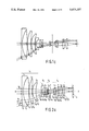
- FIGS. 1a, 1b and 1c, FIGS. 2a, 2b and 2c and FIGS. 3a, 3b and 3c show a first, a second and a third embodiment, respectively of the zoom lens, namely in the teleposition, the normal position and the wide-angle position, respectively.
- FIGS. 1a, 1b and 1c, FIGS. 2a, 2b and 2c and FIGS. 3a, 3b and 3c show a first, a second and a third embodiment, respectively of the zoom lens, namely in the teleposition, the normal position and the wide-angle position, respectively.
- Corresponding elements in the Figures have the same reference numerals.
- the zoom lens comprises a positive first lens group G 1 , also referred to as front group, consisting of three positive lens elements L 1 , L 2 and L 3 .
- This group is followed by a movable and negative group G 2 consisting of two negative lens elements L 4 and L 5 .
- the focal length can be adjusted by moving this group, which is also referred to as the variator group.
- the variator group In FIGS. 1b, 2b and 3b the variator group is in the intermediate position and the zoom lens has the average or "normal" focal length.
- FIGS. 1a, 2a and 3a show the teleposition in which the variator group is placed in the extreme right position and the focal length of the zoom lens is maximum.
- the wide-angle position of the zoom lens is shown in FIGS. 1c, 2c and 3c.
- the variator group is then in the extreme left position and the focal length is minimum.
- A, for example positive, lens group G 3 which may consist of a single lens element L 6 is arranged behind the variator group. If this lens element is positive, it converts a diverging beam emanating from the variator group into a parallel beam.
- the lens group G 3 may also be divergent to a small extent.
- a beam emanating from the lens group G 3 is focussed in the image plane IP by a fourth lens group G 4 which supplies approximately the total power of the zoom lens in the intermediate zoom position and which is referred to as the main group.
- the main group may comprise three positive lens elements L 7 , L 8 and L 9 .
- the pupil PP' of the zoom lens is in the proximity of the first lens element L 7 of the main group so that the two first lens groups are used rather eccentrically, that is to say, the marginal beams pass through these lens groups at a relatively large distance from the optical axis 00'.
- the zoom lens according to the invention is satisfactorily corrected for distortion throughout the zoom range. This can be illustrated by tracing the chief ray of the most oblique beam b 1 through the zoom lens in the two extreme situations: the teleposition and the wide-angle position.
- the angle of incidence ⁇ of the chief ray of the beam b 1 is relatively small, for example 10°.
- the elements of the front group are traversed maximally eccentrically.
- the lens elements L 1 L 2 and L 3 of this group are curved in such a manner that the maximum condition of deviation is substantially complied with per lens element, that is to say, per lens element in the front group the angle at which the chief ray is bent upon passage through this lens element is small.
- the positive spherical aberration of the chief ray of the marginal beam b 1 in the front group is relatively small with respect to the chief ray of the central beam b 0 .
- the lens elements L 4 and L 5 of the variator group G 2 are traversed relatively close to the optical axis in the teleposition and the negative spherical aberration of this lens group is relatively small. It may be ensured that the sum of the small positive and the small negative spherical aberrations compensates the spherical aberration of the main group. In the case of an ideal main group, without spherical aberration, the said sum must also be zero.
- the angle of incidence ⁇ of the chief ray of the beam b 1 is considerably larger, for example 30° than in the teleposition.
- the variator group G 2 is now located close to the front group and the rays of the beam b 1 traverse the elements of the variator group at a relatively large distance from the optical axis. Consequently, a relatively large negative spherical aberration which in itself might cause a large so-called pin-cushion distortion in the image plane IP occurs in this group.
- the net spherical aberration of the beam passing through the zoom lens is substantially equal in the teleposition and in the wide-angle position after it has traversed the telescopic lens portion comprising the lens groups G 1 , G 2 and G 3 .
- the distortion may be kept smaller than approximately 1% in all zoom ranges.
- a lens element in both in the front group G 1 , the variator group G 2 and in the main group G 4 is in the form of a doublet.
- the lens group G 3 is movable. By automatically adapting the position of this group to that of the variator group G 2 it can be ensured that the diverging beam emanating from the variator group is converted into a parallel beam. Then each sub-beam emanating from the lens portion G 1 , G 2 and G 3 is each time focussed in the image plane IP by the main group G 4 .
- the movable lens group G 3 is then a focus compensator.
- the lens group G 3 is stationary. This group can then no longer function as a focus compensator during zooming. In order to achieve that nevertheless a sharp picture is each time formed on the image sensor IS, during zooming of the beam passing through the zoom lens focussing can be detected via the image sensor or a separate focus detection device in the camera of which the zoom lens forms part. The focussing can be re-adjusted with the focus error signal obtained, for example by moving the front group G 1 .
- the object distance can also be adjusted by axial movement of the front group.
- An infrared filter F is arranged between the lens element L 7 and the lens element L 8 in the zoom lens shown in FIGS. 2a, 2b and 2c.
- the pupil PP' is at, for example 3 mm from the lens L 6 . This distance can be varied.
- the distances denoted by d 1 and d 2 in the Table above are variable.
- the following values for d 1 and d 2 apply to the different zoom distances d Z :
- the overall length of this zoom lens is approximately 89.5 mm.
- the zoom lens shown in FIGS. 3a, 3b and 3c is different from that shown in FIGS. 2a, 2b and 2c in that the lens elements L 4 and L 5 are placed closer together and in that the lens element L 6 is arranged behind the pupil PP'.
Landscapes
- Physics & Mathematics (AREA)
- General Physics & Mathematics (AREA)
- Optics & Photonics (AREA)
- Nonlinear Science (AREA)
- Lenses (AREA)
Abstract
A zoom lens is described for an electronic camera for still pictures, comprising a front group (G1), a variator group (G2) and a main group (G4). The lens is designed in such a manner that the sum of the spherical aberrations of the front group and the variator group is constant throughout the zoom range and is adapted to that of the main group.
Description
This is a continuation of application Ser. No. 293,558 filed Jan. 3, 1989 which is a continuation of application Ser. No. 057,191 filed June 3, 1987, now abandoned.
The invention relates to a zoom lens for an electronic camera with which still pictures can be picked up, which zoom lens, viewed from the object end, successively comprises a positive first lens group, a second negative lens group which is movable with respect to the first lens group, a third lens group and a stationary and positive fourth lens group, the fourth lens group being the main group which has a constant power and the first three lens groups combined constituting a lens system of small power and variable magnification.
A zoom lens of this type is known per se. U.S. Pat. No. 3,891,304 describes a zoom lens of the said composition for use in an 8-mm film camera. For a number of reasons the known zoom lens is not suitable for an electronic still picture camera.
In such a camera a photosensitive film is no longer used for recording the picked-up pictures, but these pictures are electronically recorded in order at a later stage to be reproduced via an electronic display device, such as a television picture display device, or printed. In this camera a so-called electronic image sensor is located in the image plane of the zoom lens, which sensor not only comprises a bidimensional matrix of radiation-sensitive semiconductor elements, but also electronic circuits coupled to these elements for processing and temporarily storing the picture information which is present in the electrical output signals of the radiation-sensitive elements. The image sensor has a radiation-sensitive surface whose dimensions differ from those of the image plane of a conventional photocamera or those of a conventional film camera. A commonly used electronic image sensor, for example in the form of a so-called charge-coupled device or CCD which is formed as a frame transfer device or FTD such as are used in video cameras has an image field diagonal of 11 mm. A zoom lens having a corresponding image field diagonal will have to be used when using such an image sensor in a camera for still pictures.
As compared with a zoom lens for a motion-picture camera, the lens for a still-picture camera should not only have a higher resolving power but it should also be free from distortion to a greater extent. Distortion is to be understood to mean the distortion of the image, for example the so-called barrel or pin-cushion distortion. The human eye can sooner detect a distortion or a poor resolving power in a still picture than in a moving picture.
As is known, an electronic colour image sensor comprises three types of radiation-sensitive elements each being only sensitive to the primary colours red, green and blue, respectively. These elements are juxtaposed in a regular pattern, with the elements of a first type always being surrounded by elements of the two other types. Since the radiation-sensitive elements have a given thickness, a beam portion having the size of a radiation-sensitive element may not only pass through a desired radiation-sensitive element but also through an adjacent element of another colour in the case of oblique incidence of the chief ray of an imaging beam. This might result in a colour shift in the reconstructed picture. It is therefore desirable for the zoom lens to be telecentric at the image end. In fact, the chief ray of a beam imaging a point of the object in a point of the sensor is then always perpendicularly incident on the sensor surface.
It is an object of the present invention to provide a class of zoom lenses which is specially suitable for use in an electronic camera for still pictures and thus meets the above-mentioned requirements.
To this end the zoom lens according to the invention is characterized in that the curvatures of the surfaces of the lens elements in the first and second lens groups as well as the positions of the second lens group associated with given focal lengths are such that the sum of the spherical aberration of the first lens group and that of the second lens group is constant throughout the zoom range.
The zoom range is to be understood to mean the range of focal lengths at which the lens can be adjusted.
The spherical aberration referred to in this context is the mutual spherical aberration of the chief rays of the sub-beams entering the zoom lens at different angles. This spherical aberration may also be referred to as the spherical aberration of the image of the entrance pupil, hence the image of the pupil in the object space formed by the the lens groups located in front of this pupil. The said condition implies that the chief rays of all sub-beams pass through one and the same point of the pupil.
It is essential for the zoom lens according to the invention that the distortion of the lens portion comprising the first three lens groups is constant throughout the zoom range from the telepositiion to the wide-angle position. Consequently the lens may have a telecentric design. It is true that the zoom lenses hitherto known have a very small distortion in the teleposition, but the distortion of these zoom lenses is considerable in the wide-angle position.
A further advantage of the zoom lens according to the invention, as compared with that described in U.S. Pat. No. 3,891,304, is that the maximum field angle, in the wide-angle position, for which the lens is still sufficiently free from distortion may be larger, for example 2×30° for the novel zoom lens and approximately 2×20° for the known zoom lens. The field angle is to be understood to mean the angle at which in the object space the chief ray of an obliquely incident beam which is passed by the zoom lens with an acceptable vignetting crosses the optical axis of the lens.
The zoom lens according to the invention is preferably further characterized in that in the telemode the rays of the most oblique marginal beam which enters at the angle of acceptance extend at relatively small angles to the normals on the lens elements of both the first and the second lens group, whilst these rays in the second lens group extend close to the optical axis, and the spherical aberrations of the first and second lens groups are small and compensate each other at least for the greater part, in the wide-angle mode the rays of the said marginal beam extend at relatively large angles to the normals on the lens elements of both the first and the second lens group, whilst these rays in the second lens group extend at a relatively large distance from the optical axis, and the relatively large positive spherical aberration of the first lens group and the relatively large negative spherical aberration of the second lens group compensate each other to the same extent as in the telemode.
A marginal beam is a beam from the edge of the object. The angle of acceptance is the angle at which the chief ray of the most oblique marginal beam which passes through the zoom lens with an acceptable vignetting crosses the axis of the zoom lens. The angle of acceptance is thus equal to the maximum field angle.
The remaining spherical aberration of the first two lens groups combined may in principle be equal to zero. Then the main group must also be completely corrected for spherical aberration.
However, the zoom lens according to the invention is preferably further characterized in that the constant spherical aberration of the first and second lens groups combined is equal and opposite to that of the main group.
In that case no extra steps have to be taken to render the main group on the one hand and the combination of the first and second lens groups on the other hand free from aberration.
Likewise as in the zoom lens described in U.S. Pat. No. 3,891,304, the third lens group may be movable and then serves as a focus compensator during zooming. In addition to this focus compensator the known zoom lens has a positive stationary lens group between the focus compensation and the main group.
In order to limit the axial and transversal chromatic aberration of the zoom lens, the zoom lens is further characterized in that a lens element of both the first, the second and the fourth lens group is in the form of a doublet.
A doublet is a composite lens element comprising two lens elements having different dispersions which are cemented together directly or via a layer of air and in which the internal surfaces of these lens elements have the same curvature.
The invention will now be described by way of example with reference to the accompanying drawings in which FIGS. 1a, 1b and 1c, FIGS. 2a, 2b and 2c and FIGS. 3a, 3b and 3c show a first, a second and a third embodiment, respectively of the zoom lens, namely in the teleposition, the normal position and the wide-angle position, respectively. Corresponding elements in the Figures have the same reference numerals.
Viewed from the object end, which is on the lefthand side of the drawing, the zoom lens comprises a positive first lens group G1, also referred to as front group, consisting of three positive lens elements L1, L2 and L3. This group is followed by a movable and negative group G2 consisting of two negative lens elements L4 and L5. The focal length can be adjusted by moving this group, which is also referred to as the variator group. In FIGS. 1b, 2b and 3b the variator group is in the intermediate position and the zoom lens has the average or "normal" focal length. FIGS. 1a, 2a and 3a show the teleposition in which the variator group is placed in the extreme right position and the focal length of the zoom lens is maximum. The wide-angle position of the zoom lens is shown in FIGS. 1c, 2c and 3c. The variator group is then in the extreme left position and the focal length is minimum.
A, for example positive, lens group G3 which may consist of a single lens element L6 is arranged behind the variator group. If this lens element is positive, it converts a diverging beam emanating from the variator group into a parallel beam. The lens group G3 may also be divergent to a small extent.
A beam emanating from the lens group G3 is focussed in the image plane IP by a fourth lens group G4 which supplies approximately the total power of the zoom lens in the intermediate zoom position and which is referred to as the main group. The main group may comprise three positive lens elements L7, L8 and L9.
The pupil PP' of the zoom lens is in the proximity of the first lens element L7 of the main group so that the two first lens groups are used rather eccentrically, that is to say, the marginal beams pass through these lens groups at a relatively large distance from the optical axis 00'.
The zoom lens according to the invention is satisfactorily corrected for distortion throughout the zoom range. This can be illustrated by tracing the chief ray of the most oblique beam b1 through the zoom lens in the two extreme situations: the teleposition and the wide-angle position.
In the teleposition (FIGS. 1a, 2a and 3a) the angle of incidence α of the chief ray of the beam b1 is relatively small, for example 10°. The elements of the front group are traversed maximally eccentrically. The lens elements L1 L2 and L3 of this group are curved in such a manner that the maximum condition of deviation is substantially complied with per lens element, that is to say, per lens element in the front group the angle at which the chief ray is bent upon passage through this lens element is small. The positive spherical aberration of the chief ray of the marginal beam b1 in the front group is relatively small with respect to the chief ray of the central beam b0. The lens elements L4 and L5 of the variator group G2 are traversed relatively close to the optical axis in the teleposition and the negative spherical aberration of this lens group is relatively small. It may be ensured that the sum of the small positive and the small negative spherical aberrations compensates the spherical aberration of the main group. In the case of an ideal main group, without spherical aberration, the said sum must also be zero.
In the wide-angle position the angle of incidence α of the chief ray of the beam b1 is considerably larger, for example 30° than in the teleposition. The variator group G2 is now located close to the front group and the rays of the beam b1 traverse the elements of the variator group at a relatively large distance from the optical axis. Consequently, a relatively large negative spherical aberration which in itself might cause a large so-called pin-cushion distortion in the image plane IP occurs in this group. This is, however, avoided in that due to the large angle of incidence the chief ray of the beam b1 no longer traverses the lens elements of the front group G1 in accordance with the minimum condition of deviation, so that the beam b1 has a relatively large positive spherical aberration in the front group. This aberration compensates the relatively large negative spherical aberration of the variator group at least for the greater part, so that the resultant aberration is equal to that in the teleposition.
Thus it can be achieved that the net spherical aberration of the beam passing through the zoom lens is substantially equal in the teleposition and in the wide-angle position after it has traversed the telescopic lens portion comprising the lens groups G1, G2 and G3. In the zoom lens according to the invention the distortion may be kept smaller than approximately 1% in all zoom ranges.
Preferably a lens element in both in the front group G1, the variator group G2 and in the main group G4 is in the form of a doublet. In the embodiments shown in the
Figures these are the elements L1, L5 and L7. Due to this step the chromatic aberrations can be limited; for example, the transverse colour error may be smaller than approximately 5 microns whilst the longitudinal colour error may be smaller than the depth of field of the zoom lens. Due to the different dispersions of the sub-elements of the said doublets, these elements have a chromatising effect.
In the embodiment shown in FIGS. 1a, 1b and 1c the lens group G3 is movable. By automatically adapting the position of this group to that of the variator group G2 it can be ensured that the diverging beam emanating from the variator group is converted into a parallel beam. Then each sub-beam emanating from the lens portion G1, G2 and G3 is each time focussed in the image plane IP by the main group G4. The movable lens group G3 is then a focus compensator.
In the embodiment shown in FIGS. 2a, 2b and 2c the lens group G3 is stationary. This group can then no longer function as a focus compensator during zooming. In order to achieve that nevertheless a sharp picture is each time formed on the image sensor IS, during zooming of the beam passing through the zoom lens focussing can be detected via the image sensor or a separate focus detection device in the camera of which the zoom lens forms part. The focussing can be re-adjusted with the focus error signal obtained, for example by moving the front group G1.
The object distance can also be adjusted by axial movement of the front group.
An infrared filter F is arranged between the lens element L7 and the lens element L8 in the zoom lens shown in FIGS. 2a, 2b and 2c.
For a zoom lens according to FIGS. 2a, 2b and 2c whose focal length is adjustable between 10 mm and 26 mm and whose F number is equal to F/2.8, the following values apply to the distances d between the surfaces S1. . . S23, the axial curvatures C, the refractive indices n and the diameters D of the surfaces:
______________________________________
        d (mm)
              C            n       D (mm)
______________________________________
       S.sub.1         0.000000        53.0
              2.5000             1.7918
L.sub.1
       S.sub.2         0.023375        48.0
              10.5000            1.6629
       S.sub.3         -0.006916       48.0
              0.2000             1.0000
       S.sub.4         0.020235        43.0
L.sub.2       5.6000             1.6229
       S.sub.5         0.002722        43.0
              0.2000             1.0000
       S.sub.6         0.048035        32.4
L.sub.3       6.2000             1.6940
       S.sub.7         0.017590        32.4
              d.sub.1            1.0000
       S.sub.8         0.002597        19.0
L.sub.4       1.0000             1.6940
       S.sub.9         0.146508        12.2
              5.2000             1.0000
       S.sub.10        -0.031813       11.8
              3.5000             1.7918
L.sub.5
       S.sub.11        -0.132204       11.8
              1.0000             1.6229
       S.sub.12        0.019499        11.8
              d.sub.2            1.0000
       S.sub.13        -0.025002        9.0
L.sub.6       1.2000             1.6229
                       -0.065947        9.0
       S.sub.14
              9.4102             1.0000
       S.sub.15        -0.020507       10.2
              3.5000             1.7923
L.sub.7
       S.sub.16        -0.170711       10.2
              1.000              1.7918
       S.sub.17        -0.047777       12.0
              2.8052             1.0000
       S.sub.18        0.000000        16.0
F             1.0000             1.5187
       S.sub.19        0.000000        16.0
              3.0000             1.0000
       S.sub.20        0.006476        16.0
L.sub.8       3.0000             1.6229
       S.sub.21        -0.025250       16.0
              1.3156             1.0000
       S.sub.22        0.043493        16.0
L.sub.9       3.0000             1.6229
       S.sub.23        0.000000        16.0
______________________________________
The pupil PP' is at, for example 3 mm from the lens L6. This distance can be varied. The distances denoted by d1 and d2 in the Table above are variable. The following values for d1 and d2 apply to the different zoom distances dZ :
______________________________________
d.sub.Z         d.sub.1 (mm)
                         d.sub.2 (mm)
______________________________________
f = 26 mm       9.5360   0.6692
f = 16 mm       5.9749   4.2229
f = 10 mm       1.7391   8.4575
______________________________________
The overall length of this zoom lens is approximately 89.5 mm.
The zoom lens shown in FIGS. 3a, 3b and 3c is different from that shown in FIGS. 2a, 2b and 2c in that the lens elements L4 and L5 are placed closer together and in that the lens element L6 is arranged behind the pupil PP'.
For a zoom lens as shown in FIGS. 3a, 3b and 3c whose focal length is adjustable between 10.5 mm and 25 mm and whose F number can be adjusted between F/4.0 and F/2.8, the following values apply to the distances d between the surfaces S1. . . S23, the axial curvatures C, the refractive indices n and the diameters D of the surfaces:
______________________________________
        d (mm)
              C            n       D (mm)
______________________________________
       S.sub.1         0.000064        52.8
              2.5000             1.7918
L.sub.1
       S.sub.2         0.016701        49.0
              8.4000             1.6629
       S.sub.3         -0.005420       49.0
              0.2000             1.0000
       S.sub.4         0.021750        44.0
L.sub.2       5.9000             1.6229
       S.sub.5         0.004915        44.0
              0.2000             1.0000
       S.sub.6         0.036099        35.0
L.sub.3       5.1000             1.6940
       S.sub.7         0.014637        35.0
              d.sub.1            1.0000
       S.sub.8         0.000000        19.0
L.sub.4       1.2000             1.6940
       S.sub.9         0.128381        12.7
              4.3000             1.0000
       S.sub.10        -0.043571       12.6
              3.1000             1.7918
       S.sub.11        -0.115245       12.6
              1.0000             1.6229
       S.sub.12        -0.007312       13.5
              d.sub.2            1.0000
       PP'             0.000000         4.4
              3.5000             1.0000
       S.sub.13        -0.008706         9.0
L.sub.6       1.4000             1.6229
       S.sub.14        -0.055360        9.0
              5.7716             1.0000
       S.sub.15        -0.007096       11.7
              3.3000             1.7923
L.sub.7
       S.sub.16        -0.131079       11.7
              1.0000             1.7918
       S.sub.17        -0.031244       14.0
              4.8592             1.0000
       S.sub.18        0.000000        16.0
F             1.0000             1.5187
       S.sub.19        0.000000        16.0
              3.000              1.0000
       S.sub.20        0.009431        17.0
L.sub.8       3.0000             1.6229
       S.sub.21        -0.017628       17.0
              0.2000             1.0000
       S.sub.22        0.039210        18.0
L.sub.9       3.0000             1.6229
       S.sub.23        0.007229        18.0
______________________________________
The following values for d1 and d2 apply to the different zoom distances dZ :
______________________________________
d.sub.Z          d.sub.1 (mm)
                          d.sub.2 (mm)
______________________________________
f = 25 mm        13.0499  3.7591
f = 16 mm        8.5994   8.1989
  f = 10.7 mm    3.8037   12.9857
______________________________________
Claims (6)
1. A zoom lens for an electronic still camera which, viewed from the object end, successively comprises a positive first lens group, a second negative lens group movable with respect to said first lens group, a third lens group and a stationary and positive fourth lens group, said fourth lens group being the main lens group which has a constant power and the first three lens groups combined constituting a lens system of small power and variable magnification, wherein the curvatures of the surfaces of the lens elements in said first and second lens groups as well as the positions of said second lens group associated with given focal lengths are such that the sum of the spherical aberration of said first lens group and that of said second lens group is a constant, including zero, throughout the zoom range and equal and opposite to that of said main lens group.
2. A zoom lens as claimed in claim 1, characterized in that
in the telemode the rays of the most oblique marginal beam which enters at the angle of acceptance extend at relatively small angles to the normals on the lens elements of both said first and said second lens groups, whilst these rays in said second lens group extend close to the optical axis, and the spherical aberrations of said first and second lens groups are small and compensate each other at least for the greater part, and in that
in the wide-angle mode the rays of said marginal beam extend at relatively large angles to the normals on the lens elements of both said first and said second lens groups, whilst these rays in said second lens group extend at a relatively large distance from said optical axis, and the relatively large positive spherical aberration of said first lens group and the relatively large negative spherical aberration of said second lens group compensate each other to the same extent as in the telemode.
3. A zoom lens as claimed in claim 1 or 2, characterized in that a lens element of the first, the second and the fourth lens group is a doublet.
4. A zoom lens for an electronic still camera, which viewed from the object end, successively comprises a positive first lens group, a second negative lens group movable with respect to the first lens group, a third lens group and a stationary and positive fourth lens group, said fourth lens group being the main lens group which has a constant power and the first three lens groups combined constituting a lens system of small power and variable magnification, wherein the curvatures of the surfaces of the lens elements in said first and second lens groups as well as the positions of said second lens group associated with given focal lengths are such that the sum of the spherical aberration of said first lens group and that of said second lens group is a constant, including zero, through-out the zoom range.
5. A zoom lens as claimed in claim 4, wherein:
in the telemode the rays of the most oblique marginal beam which enters at the angle of acceptance extend at relatively small angles to the normals on the lens elements of both the first and second lens group, while these rays in the second lens group extend close to the optical axis, and the spherical aberrations of the first and second lens groups are small and compensate each other at least for the greater part, and in that
in the wide-angle mode of the rays of the said marginal beam extend at relatively large angles to the normals on the lens elements of both the first and the second lens group, while these rays in the second lens group extend at a relatively large distance from the optical axis, and the relatively large positive spherical aberration of the first lens group and the relatively large negative spherical aberration of the second lens group compensate each other to the same extent as in the telemode.
6. A zoom lens as claimed in claim 4 wherein a lens element of the first, second and fourth lens group is a doublet.
Applications Claiming Priority (2)
| Application Number | Priority Date | Filing Date | Title |
|---|---|---|---|
| NL8700059 | 1987-01-13 | ||
| NL8700059A NL8700059A (en) | 1987-01-13 | 1987-01-13 | ZOOM LENS FOR AN ELECTRONIC CAMERA. |
Related Parent Applications (1)
| Application Number | Title | Priority Date | Filing Date |
|---|---|---|---|
| US07293558 Continuation | 1989-01-03 |
Publications (1)
| Publication Number | Publication Date |
|---|---|
| US5071237A true US5071237A (en) | 1991-12-10 |
Family
ID=19849400
Family Applications (1)
| Application Number | Title | Priority Date | Filing Date |
|---|---|---|---|
| US07/497,747 Expired - Lifetime US5071237A (en) | 1987-01-13 | 1990-03-19 | Zoom lens for an electronic camera |
Country Status (7)
| Country | Link |
|---|---|
| US (1) | US5071237A (en) |
| EP (1) | EP0278126B1 (en) |
| JP (1) | JPH0644099B2 (en) |
| KR (1) | KR970003767B1 (en) |
| DE (1) | DE3787462T2 (en) |
| HK (1) | HK163695A (en) |
| NL (1) | NL8700059A (en) |
Cited By (4)
| Publication number | Priority date | Publication date | Assignee | Title |
|---|---|---|---|---|
| US5587739A (en) * | 1993-03-26 | 1996-12-24 | Nikon Corporation | Variable magnification image taking device |
| US20020154415A1 (en) * | 2001-01-18 | 2002-10-24 | Yuji Miyauchi | Image pickup system |
| RU2276800C1 (en) * | 2004-12-16 | 2006-05-20 | Федеральное государственное унитарное предприятие "Центральное конструкторское бюро точного приборостроения" Российского агентства по обычным вооружениям | Objective with variable focal distance |
| US10324279B2 (en) | 2016-06-08 | 2019-06-18 | Young Optics Inc. | Optical lens |
Families Citing this family (2)
| Publication number | Priority date | Publication date | Assignee | Title |
|---|---|---|---|---|
| JP4496009B2 (en) * | 2004-05-17 | 2010-07-07 | 株式会社リコー | Information device having zoom lens and photographing function |
| JP4764644B2 (en) * | 2005-02-23 | 2011-09-07 | 株式会社リコー | Zoom lens and information device |
Citations (3)
| Publication number | Priority date | Publication date | Assignee | Title |
|---|---|---|---|---|
| US3891304A (en) * | 1972-01-13 | 1975-06-24 | Vockenhuber Karl | Pancratic objective |
| US4518228A (en) * | 1982-10-15 | 1985-05-21 | Canon Kabushiki Kaisha | Zoom lens |
| US4763998A (en) * | 1985-06-26 | 1988-08-16 | Canon Kabushiki Kaisha | Compact zoom lens |
Family Cites Families (4)
| Publication number | Priority date | Publication date | Assignee | Title |
|---|---|---|---|---|
| US4390248A (en) * | 1979-09-27 | 1983-06-28 | Canon Kabushiki Kaisha | Wide angle zoom lens |
| JPS5754911A (en) * | 1980-09-18 | 1982-04-01 | Canon Inc | Zoom lens having telecentric relay part |
| US4525036A (en) * | 1982-03-08 | 1985-06-25 | Tokyo Shibaura Denki Kabushiki Kaisha | Zoom lens |
| JPS6139016A (en) * | 1984-07-31 | 1986-02-25 | Ricoh Co Ltd | Compact zoom lens |
-
1987
- 1987-01-13 NL NL8700059A patent/NL8700059A/en not_active Application Discontinuation
- 1987-12-29 DE DE87202643T patent/DE3787462T2/en not_active Expired - Fee Related
- 1987-12-29 EP EP87202643A patent/EP0278126B1/en not_active Expired - Lifetime
-
1988
- 1988-01-11 JP JP63002636A patent/JPH0644099B2/en not_active Expired - Fee Related
- 1988-01-11 KR KR1019880000125A patent/KR970003767B1/en not_active Expired - Fee Related
-
1990
- 1990-03-19 US US07/497,747 patent/US5071237A/en not_active Expired - Lifetime
-
1995
- 1995-10-19 HK HK163695A patent/HK163695A/en not_active IP Right Cessation
Patent Citations (3)
| Publication number | Priority date | Publication date | Assignee | Title |
|---|---|---|---|---|
| US3891304A (en) * | 1972-01-13 | 1975-06-24 | Vockenhuber Karl | Pancratic objective |
| US4518228A (en) * | 1982-10-15 | 1985-05-21 | Canon Kabushiki Kaisha | Zoom lens |
| US4763998A (en) * | 1985-06-26 | 1988-08-16 | Canon Kabushiki Kaisha | Compact zoom lens |
Cited By (7)
| Publication number | Priority date | Publication date | Assignee | Title |
|---|---|---|---|---|
| US5587739A (en) * | 1993-03-26 | 1996-12-24 | Nikon Corporation | Variable magnification image taking device |
| US20020154415A1 (en) * | 2001-01-18 | 2002-10-24 | Yuji Miyauchi | Image pickup system |
| US20060158741A1 (en) * | 2001-01-18 | 2006-07-20 | Yuji Miyauchi | Image pickup system |
| US7116487B2 (en) * | 2001-01-18 | 2006-10-03 | Olympus Corporation | Image pickup system |
| US7136230B2 (en) * | 2001-01-18 | 2006-11-14 | Olympus Corporation | Image pickup system |
| RU2276800C1 (en) * | 2004-12-16 | 2006-05-20 | Федеральное государственное унитарное предприятие "Центральное конструкторское бюро точного приборостроения" Российского агентства по обычным вооружениям | Objective with variable focal distance |
| US10324279B2 (en) | 2016-06-08 | 2019-06-18 | Young Optics Inc. | Optical lens |
Also Published As
| Publication number | Publication date |
|---|---|
| JPS63180926A (en) | 1988-07-26 |
| HK163695A (en) | 1995-10-27 |
| KR880009284A (en) | 1988-09-14 |
| EP0278126A1 (en) | 1988-08-17 |
| DE3787462T2 (en) | 1994-04-07 |
| DE3787462D1 (en) | 1993-10-21 |
| NL8700059A (en) | 1988-08-01 |
| JPH0644099B2 (en) | 1994-06-08 |
| KR970003767B1 (en) | 1997-03-21 |
| EP0278126B1 (en) | 1993-09-15 |
Similar Documents
| Publication | Publication Date | Title |
|---|---|---|
| KR100463479B1 (en) | Photographing lens system | |
| US8619368B2 (en) | Whole beam image splitting system | |
| EP0566073B1 (en) | Zoom lens assembly | |
| US8045274B2 (en) | Zoom lens and image pickup apparatus using the same | |
| US20110157715A1 (en) | Zoom lens and image pickup apparatus including the same | |
| JP3741788B2 (en) | Imaging lens | |
| JP2002162562A (en) | Shooting lens | |
| US6222685B1 (en) | Imaging lens | |
| JP3672278B2 (en) | Imaging lens | |
| JP3514318B2 (en) | Shooting lens | |
| US5071237A (en) | Zoom lens for an electronic camera | |
| EP4425256A3 (en) | Folded macro-tele camera lens designs | |
| JP2001356269A (en) | Zoom lens | |
| JP2001100094A (en) | Shooting lens | |
| JP2001100091A (en) | Shooting lens | |
| US5703716A (en) | Re-imaging converter lens apparatus and method | |
| JPS6411924B2 (en) | ||
| JPH08179207A (en) | Imaging optical system | |
| JPS6396618A (en) | Image pickup device | |
| JP3511392B2 (en) | Imaging lens with three balls | |
| JPS6396616A (en) | Image pickup device | |
| JPH1184232A (en) | Wide angle lens | |
| JPS6396617A (en) | Imaging device | |
| JP2000180715A (en) | Imaging equipment | |
| JP3252227B2 (en) | Camera with large aperture wide-angle zoom lens |
Legal Events
| Date | Code | Title | Description |
|---|---|---|---|
| STCF | Information on status: patent grant |
Free format text: PATENTED CASE |
|
| FEPP | Fee payment procedure |
Free format text: PAYOR NUMBER ASSIGNED (ORIGINAL EVENT CODE: ASPN); ENTITY STATUS OF PATENT OWNER: LARGE ENTITY |
|
| FPAY | Fee payment |
Year of fee payment: 4 |
|
| FPAY | Fee payment |
Year of fee payment: 8 |
|
| FPAY | Fee payment |
Year of fee payment: 12 |