US5069467A - Front shock absorbing unit for motorcycles - Google Patents
Front shock absorbing unit for motorcycles Download PDFInfo
- Publication number
- US5069467A US5069467A US07/526,510 US52651090A US5069467A US 5069467 A US5069467 A US 5069467A US 52651090 A US52651090 A US 52651090A US 5069467 A US5069467 A US 5069467A
- Authority
- US
- United States
- Prior art keywords
- frame
- pivoted
- fork
- secured
- shock absorbing
- Prior art date
- Legal status (The legal status is an assumption and is not a legal conclusion. Google has not performed a legal analysis and makes no representation as to the accuracy of the status listed.)
- Expired - Fee Related
Links
- 230000035939 shock Effects 0.000 title claims abstract description 43
- 239000006096 absorbing agent Substances 0.000 claims description 15
- 238000010521 absorption reaction Methods 0.000 description 1
- 238000005452 bending Methods 0.000 description 1
- 238000006243 chemical reaction Methods 0.000 description 1
- 230000006835 compression Effects 0.000 description 1
- 238000007906 compression Methods 0.000 description 1
- 230000007547 defect Effects 0.000 description 1
- 230000000694 effects Effects 0.000 description 1
- 230000005484 gravity Effects 0.000 description 1
- 238000010008 shearing Methods 0.000 description 1
Images


Classifications
-
- B—PERFORMING OPERATIONS; TRANSPORTING
- B62—LAND VEHICLES FOR TRAVELLING OTHERWISE THAN ON RAILS
- B62K—CYCLES; CYCLE FRAMES; CYCLE STEERING DEVICES; RIDER-OPERATED TERMINAL CONTROLS SPECIALLY ADAPTED FOR CYCLES; CYCLE AXLE SUSPENSIONS; CYCLE SIDE-CARS, FORECARS, OR THE LIKE
- B62K25/00—Axle suspensions
- B62K25/04—Axle suspensions for mounting axles resiliently on cycle frame or fork
- B62K25/12—Axle suspensions for mounting axles resiliently on cycle frame or fork with rocking arm pivoted on each fork leg
- B62K25/22—Axle suspensions for mounting axles resiliently on cycle frame or fork with rocking arm pivoted on each fork leg with more than one arm on each fork leg
- B62K25/24—Axle suspensions for mounting axles resiliently on cycle frame or fork with rocking arm pivoted on each fork leg with more than one arm on each fork leg for front wheel
Definitions
- the present invention concerns a front shock absorbing unit for motorcycles.
- shock absorption on the front wheel of motorcycles and similar vehicles is effected by means of telescopic forks, the operation of which depends on elastic means assisted by hydraulic or gas devices.
- Forks of this kind have numerous disadvantages, even when they are of the highest quality, as in the case of those for competition motorcycles.
- shock absorbers of the known type are due basically to the fact that the front wheel assembly tends to become deformed under the effect of the remarkable shearing, bending and torsional stresses it is subjected to, especially at high speed.
- the object of the present invention is to create a shock absorbing unit for the front wheel of motorcycles which is free from the disadvantages previously described.
- this may be achieved by providing a deformable structure with an upper and lower fork each including a plurality of arms, pivoted on a first end to a sleeve that is integral with the stanchions which are themselves pivoted to the wheel hub, and, on a second fork end, where the fork arms are at their widest distance apart, the upper fork is pivoted to the frame and the lower fork is pivoted to a pair of link rods which are in turn pivoted to the frame.
- a plurality of first pins at the ends second of the forks are mutually connected to a cross, and a plurality of second pins connecting to the frame are linked to rods in which one each there is fixed a tube for supporting the handlebar.
- Each tube is secured at a first joint by means of a structure which includes a plurality of rods which are secured at a second joint to the upper ends of the stanchions connected to the wheel hub wherein a plate slides on the plurality of rods.
- a tie rod pivoted on one end to each of the arms of the upper fork, another end of the tie rod being pivoted to a first end of a lever which is centrally pivoted to the frame and is pivoted at its other end to one end of a shock absorbing element.
- the shock absorbing element is pivoted to the frame at its opposite end and located in such a way as to correspond to a longitudinal plane of symmetry of the frame.
- the connecting pins between the link rods and the frame present an eccentric element which varies the angular position by which the shape of the entire shock absorbing unit is modified, especially the angle of the stanchions with respect to the vertical. This makes it possible to adapt the position of the stanchions themselves to the changed requirements of the rider, in relation to the course which the rider is following.
- FIG. 1 is a schematic side view of a motorcycle to which the shock absorbing device may be applied.
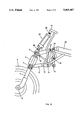
- FIG. 2 is a side view of the shock absorbing device.
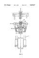
- FIGS. 3 and 4 are front elevational views of the device, respectively with and without some of its components.
- FIG. 5 is a front elevational view of the shock absorbing device, without some of its components.
- FIGS. 6 and 7 are side views of the shock absorbing device which highlight the possibility of varying the angle of the stanchions relative to the front wheel.
- the invention includes a pair of rigid stanchions 1, the lower ends of each of which are pivoted to a hub 2 of a front wheel 3, and the upper ends of each of which are integrally attached to a support sleeve 4.
- Two forks 5 and 6 are pivoted to the stanchions at points 7 and 8, respectively.
- the forks are arranged in such a way that the area in which they are furthest apart is towards the rear of the motorcycle.
- Each pair of pins 9 and 12 which are located on the same side of the motorcycle are linked by a rod 13.
- Pins 9 and 10 are linked to a fixed cross 14 (FIG. 4).
- Two tie rods 16 are pivoted at point 19 to the two arms of the upper fork 6, the opposite ends of the tie rods 16 being pivoted at point 17 to an arm 18 of a lever which is in turn pivoted to the frame at point 15.
- the opposite ends of the upper fork arms are pivoted at point 20 to head 21 of a shock absorber 22, which is of hydraulic type for example.
- the rear end of a the shock absorber is pivoted to the motorcycle frame at point 23 and is located in such a way as to correspond to the plane of symmetry of the frame.
- the motorcycle handlebar which for simplicity is not illustrated, is supported by tubes 24 which are integrally attached to rods 13.
- a supporting element 25 which is attached by means of a universal joint 26 to a structure 27 that includes a plurality of rods 28 on which there slides a plate 29 which is attached by means of another universal joint 30 to the upper end of sleeve 4 which is fixed integrally to stanchions 1 (FIG. 3).
- the articulated framework described above is designed to absorb the shock by yielding to the force which tends to deform it.
- stanchions 1 and, hence sleeve 4 are designed to move up and to carry pins 7 and 8 with them, in such a manner as to cause forks 5 and 6 to rotate upwards about pins 9 and 12 which connect the shock absorber to the motorcycle frame, pins 9 and 12 obviously remain fixed in relation to the frame.
- shock absorber 22 which obviously reacts with a force which tends to move arm 18 back to the position illustrated in the drawing.
- the shape of the system is such that this reaction occurs extremely rapidly and effectively, enabling the entire system, after every shock, to return very rapidly to the position illustrated in the drawing.
- the present shock absorber eliminates the defect typical of shock absorbers presently known whereby the stanchions sink deeply into their cylinders whenever the shock absorber is subjected to strain.
- shock absorber is positioned centrally on the frame prevents all possible strain, be it torsional, flexural or other, on the moving parts, which occurs in known shock absorbers.
- FIGS. 6 and 7 show that the device is even more effective if pins 12 are housed eccentrically in a cylindrical structure 31 that is able to rotate about its own axis within a seating made transversely on link rod 11.
Landscapes
- Engineering & Computer Science (AREA)
- Mechanical Engineering (AREA)
- Axle Suspensions And Sidecars For Cycles (AREA)
Abstract
The present invention pertains to a front shock absorbing unit for motorcycles, whose main characteristic is that the shock absorbing element (22), pivoted to the frame (23), is located in such a way as to correspond to the longitudinal plane of symmetry of the frame, and is connected by means of a pin (20) to an articulated structure (5, 6, 11, 13, 16, 18) which includes in particular two forks (5 and 6) pivoted to the stanchions (1) which in turn are pivoted to the hub (2) of front wheel (3) (FIG. 1).
Description
The present invention concerns a front shock absorbing unit for motorcycles.
At the present time, shock absorption on the front wheel of motorcycles and similar vehicles is effected by means of telescopic forks, the operation of which depends on elastic means assisted by hydraulic or gas devices. Forks of this kind have numerous disadvantages, even when they are of the highest quality, as in the case of those for competition motorcycles.
The disadvantages presented by the shock absorbers of the known type are due basically to the fact that the front wheel assembly tends to become deformed under the effect of the remarkable shearing, bending and torsional stresses it is subjected to, especially at high speed.
The object of the present invention is to create a shock absorbing unit for the front wheel of motorcycles which is free from the disadvantages previously described.
According to the invention, this may be achieved by providing a deformable structure with an upper and lower fork each including a plurality of arms, pivoted on a first end to a sleeve that is integral with the stanchions which are themselves pivoted to the wheel hub, and, on a second fork end, where the fork arms are at their widest distance apart, the upper fork is pivoted to the frame and the lower fork is pivoted to a pair of link rods which are in turn pivoted to the frame. A plurality of first pins at the ends second of the forks are mutually connected to a cross, and a plurality of second pins connecting to the frame are linked to rods in which one each there is fixed a tube for supporting the handlebar.
Each tube is secured at a first joint by means of a structure which includes a plurality of rods which are secured at a second joint to the upper ends of the stanchions connected to the wheel hub wherein a plate slides on the plurality of rods. In addition, there is a tie rod pivoted on one end to each of the arms of the upper fork, another end of the tie rod being pivoted to a first end of a lever which is centrally pivoted to the frame and is pivoted at its other end to one end of a shock absorbing element. The shock absorbing element is pivoted to the frame at its opposite end and located in such a way as to correspond to a longitudinal plane of symmetry of the frame.
In one embodiment of the invention as claimed below, the connecting pins between the link rods and the frame present an eccentric element which varies the angular position by which the shape of the entire shock absorbing unit is modified, especially the angle of the stanchions with respect to the vertical. This makes it possible to adapt the position of the stanchions themselves to the changed requirements of the rider, in relation to the course which the rider is following.
These and other characteristics of the present disclosure are highlighted in the following detailed description of its preferred, although not sole, embodiment, with reference to the accompanying drawings, where:
FIG. 1 is a schematic side view of a motorcycle to which the shock absorbing device may be applied.
FIG. 2 is a side view of the shock absorbing device.
FIGS. 3 and 4 are front elevational views of the device, respectively with and without some of its components.
FIG. 5 is a front elevational view of the shock absorbing device, without some of its components.
FIGS. 6 and 7 are side views of the shock absorbing device which highlight the possibility of varying the angle of the stanchions relative to the front wheel.
The illustrations listed above show that the invention includes a pair of rigid stanchions 1, the lower ends of each of which are pivoted to a hub 2 of a front wheel 3, and the upper ends of each of which are integrally attached to a support sleeve 4.
Two forks 5 and 6 are pivoted to the stanchions at points 7 and 8, respectively. The forks are arranged in such a way that the area in which they are furthest apart is towards the rear of the motorcycle.
While the ends of upper fork 6 are pivoted to the motorcycle frame at point 9, the ends of the arms of fork 5 are pivoted to a link rod 11 at point 10, the link rod being in turn pivoted to the fixed frame structure at point 12.
Each pair of pins 9 and 12 which are located on the same side of the motorcycle are linked by a rod 13.
Two tie rods 16 are pivoted at point 19 to the two arms of the upper fork 6, the opposite ends of the tie rods 16 being pivoted at point 17 to an arm 18 of a lever which is in turn pivoted to the frame at point 15.
The opposite ends of the upper fork arms are pivoted at point 20 to head 21 of a shock absorber 22, which is of hydraulic type for example.
The rear end of a the shock absorber is pivoted to the motorcycle frame at point 23 and is located in such a way as to correspond to the plane of symmetry of the frame.
The motorcycle handlebar, which for simplicity is not illustrated, is supported by tubes 24 which are integrally attached to rods 13.
At the upper end of tubes 24 is a supporting element 25, which is attached by means of a universal joint 26 to a structure 27 that includes a plurality of rods 28 on which there slides a plate 29 which is attached by means of another universal joint 30 to the upper end of sleeve 4 which is fixed integrally to stanchions 1 (FIG. 3).
Consequently, when the front wheel 3 encounters a sudden depression in the road, which with the known devices causes the stanchions of the shock absorbers to sink deeply into their cylinders, the articulated framework described above is designed to absorb the shock by yielding to the force which tends to deform it.
In particular, the stanchions 1 and, hence sleeve 4, are designed to move up and to carry pins 7 and 8 with them, in such a manner as to cause forks 5 and 6 to rotate upwards about pins 9 and 12 which connect the shock absorber to the motorcycle frame, pins 9 and 12 obviously remain fixed in relation to the frame.
This results in the shifting of tie rods 16 and hence the rotation of arm 18 about pin 19 (in a clockwise direction, with reference to FIG. 1).
This results in the compression of shock absorber 22 which obviously reacts with a force which tends to move arm 18 back to the position illustrated in the drawing.
The shape of the system is such that this reaction occurs extremely rapidly and effectively, enabling the entire system, after every shock, to return very rapidly to the position illustrated in the drawing.
In practice, the present shock absorber eliminates the defect typical of shock absorbers presently known whereby the stanchions sink deeply into their cylinders whenever the shock absorber is subjected to strain.
In particular, when the motorcycle is braked suddenly, the front wheel stanchions hardly move down at all, thanks to the special structure of this system.
Moreover, the fact that the shock absorber is positioned centrally on the frame prevents all possible strain, be it torsional, flexural or other, on the moving parts, which occurs in known shock absorbers.
Other advantages of the present invention are that the center of gravity of the entire motorcycle is lower than usual. Also, during the operation of the shock absorber, the distance between the wheel centers does not undergo any variation.
FIGS. 6 and 7 show that the device is even more effective if pins 12 are housed eccentrically in a cylindrical structure 31 that is able to rotate about its own axis within a seating made transversely on link rod 11.
Obviously, when this cylindrical structure rotates, the position of pin 12 changes in such a way as to modify the angle of the stanchions with respect to the vertical. In particular, the position shown in FIG. 6 is suitable for straight courses with few curves, while the position shown in FIG. 7 is particularly suitable for tortuous courses.
Claims (8)
1. A front shock absorbing unit for motorcycles comprising a deformable structure with an upper fork and a lower fork, each including a plurality of arms, said forks each being pivoted on a first end to a sleeve which is integrally attached to a pair of stanchions fixed to a hub of a wheel, and, on a second end, where the forks are at their widest distance apart, the upper fork is pivoted on second end by pins to the frame of the motorcycle and the lower fork is pivoted by pins to a pair of link rods which are in turn pivoted by pins to the frame, wherein said pins located at the second end of the forks are mutually connected to a cross, and wherein those pins which are connected to the frame on each side thereof are linked in pairs by a first rod to which there is fixed a tube for supporting a handlebar, said tube being secured at a first joint by means of a structure which includes a plurality of second rods, said structure being secured at a second joint to the upper ends of the stanchions connected to the wheel hub, wherein a plate slides on said plurality of second rods, and further comprising a tie rod pivoted at one end to each of the arms of the upper fork, the other end of said tie rod being pivoted to an end of a lever which is centrally pivoted to the frame and is pivoted at its other end to one end of a shock absorbing element, said shock absorbing element being pivoted at its other end to the frame wherein said shock absorbing element extends along a longitudinal plane of symmetry of the frame.
2. A front shock absorbing unit for motorcycles as in claim 1 wherein the pins with which the link rods are connected to the frame, are housed eccentrically in a cylindrical structure within a seating made transversely on said link rod, said cylindrical structure being capable of effecting angular movements about its own axis.
3. A front shock absorbing unit for motorcycles which comprises:
(a) a pair of stanchions fixed to a hub of a wheel;
(b) a sleeve which is integrally attached to the stanchions;
(c) an upper fork and a lower fork, each including a plurality of fork arms;
(d) a first pivot means for pivoting the forks at a first fork end to the sleeve;
(e) a second pivot means for pivoting the forks at a second fork end, where the fork arms are at their widest distance apart, such that the upper fork is pivoted to a frame and the lower fork is pivoted to a pair of link rods which are in turn pivoted to the frame;
(f) a cross pivotally connecting the forks to each other at the second fork ends;
(g) a first rod pivotally secured on each side of the frame;
(h) a tube secured to each first rod wherein the tube is secured at a second end by a first joint to a structure which includes a plurality of second rods, said structure being secured at a second joint to the upper ends of the stanchions, wherein a plate slides on said rods;
(i) a pair of tie rods each pivoted at a first rod end to the upper fork, a second end of each tie rod being pivoted to a first end of a lever which is centrally pivoted to the frame;
(j) a shock absorbing element which is pivoted, at a first end, to a second end of the lever and pivoted at its second end to the frame, said shock absorbing element extending along a longitudinal plane of symmetry of the frame.
4. An articulated front shock absorbing unit for motorcycles, comprising:
an upper fork having first and second ends;
a lower fork having first and second ends;
a stanchion means for rotatably supporting a wheel;
a sleeve secured to the stanchion means, wherein said upper and lower forks are each pivotally secured at said first ends thereof to said sleeve;
a frame, wherein said second end of said upper fork is pivotally secured to said frame;
a link rod means for pivotally securing said second end of said lower fork to said frame;
a cross securing said first and second forks to each other adjacent said second ends of said first and second forks;
a support means, secured to said frame, for supporting a handlebar;
a structure including a plurality of rods, said structure having a first end and a second end, said structure being secured by a first joint at said first end to said support means and being secured at said second end by a second joint to said stanchion means;
a tie rod secured at a first end to said upper fork;
an arm having a first end to which a second end of said tie rod is pivotally secured, said arm being pivoted to said frame; and,
a shock absorber having a first end to which a second end of said arm is pivotally secured, said shock absorber having a second end which is pivotally secured to said frame, wherein said shock absorber extends along a longitudinal axis of said frame.
5. The shock absorbing unit of claim 4 comprising a plate which is slideably mounted on said plurality of rods of said structure.
6. The shock absorbing unit of claim 4 wherein said first and second joints each comprise universal joints.
7. The shock absorbing unit of claim 4 wherein said support means comprises:
first and second rods which are spaced from each other and are each pivotally secured to said frame;
first and second tubes which are spaced from each other and are fixedly secured, respectively, to said first and second rods; and
a supporting element fixedly secured to said first and second tubes.
8. The shock absorbing unit of claim 4 wherein said lower fork second end includes first and second legs and wherein said link rod means comprises:
a first link rod pivotally secured at a first end to said lower fork second end first leg and pivotally secured at a second end to said frame; and,
a second link rod pivotally secured at a first end to said lower fork second end second leg and pivotally secured at a second end to said frame.
Applications Claiming Priority (2)
| Application Number | Priority Date | Filing Date | Title |
|---|---|---|---|
| IT8559A/89 | 1989-05-24 | ||
| IT855989 | 1989-05-24 |
Publications (1)
| Publication Number | Publication Date |
|---|---|
| US5069467A true US5069467A (en) | 1991-12-03 |
Family
ID=11126856
Family Applications (1)
| Application Number | Title | Priority Date | Filing Date |
|---|---|---|---|
| US07/526,510 Expired - Fee Related US5069467A (en) | 1989-05-24 | 1990-05-21 | Front shock absorbing unit for motorcycles |
Country Status (1)
| Country | Link |
|---|---|
| US (1) | US5069467A (en) |
Cited By (46)
| Publication number | Priority date | Publication date | Assignee | Title |
|---|---|---|---|---|
| EP0731017A1 (en) * | 1995-03-09 | 1996-09-11 | Bayerische Motoren Werke Aktiengesellschaft, Patentabteilung AJ-3 | Telescopic front suspension for a motorcycle |
| US5599034A (en) * | 1994-02-24 | 1997-02-04 | Brigden; Paul H. | Single arm bicycle suspension fork |
| US6349784B1 (en) * | 1998-01-05 | 2002-02-26 | Chiqane B.V. | Motorcycle provided with a steering hub |
| USD458194S1 (en) | 2001-07-03 | 2002-06-04 | Honda Giken Kogyo Kabushiki Kaisha | Portion of a motorcycle monofork |
| US20040094931A1 (en) * | 2002-11-15 | 2004-05-20 | Ackley Erick J. | Suspension system |
| US20050156401A1 (en) * | 2003-12-16 | 2005-07-21 | Pierre Terblanche | Front suspension for a motorcycle |
| US20050167168A1 (en) * | 2004-01-29 | 2005-08-04 | Puzey Michael R. | Vehicle and vehicle suspension system |
| US20060037799A1 (en) * | 2004-08-19 | 2006-02-23 | Mathon Albert W | Heavy duty low rise motorcycle |
| US20060037797A1 (en) * | 2004-08-19 | 2006-02-23 | Mathon Albert W | Heavy duty low rise motorcyle |
| US20060279059A1 (en) * | 2003-07-31 | 2006-12-14 | Michael Czysz | Coaxial steering and suspension for motorcycle |
| US20070194553A1 (en) * | 2006-02-06 | 2007-08-23 | Michael Czysz | Front End Lateral Suspension |
| US20080129009A1 (en) * | 2006-02-06 | 2008-06-05 | Motoczysz Llc | Front end lateral suspension |
| US20150274245A1 (en) * | 2014-03-31 | 2015-10-01 | Honda Motor Co., Ltd. | Steering structure for saddle type vehicle |
| US20150274249A1 (en) * | 2014-03-31 | 2015-10-01 | Honda Motor Co., Ltd. | Front suspension structure for saddle riding type vehicle |
| US20150307153A1 (en) * | 2014-04-15 | 2015-10-29 | HULL Loni | Suspension and steering assembly |
| US20150329169A1 (en) * | 2012-12-19 | 2015-11-19 | Robert Rae | Suspension system for the front wheel of single-track two- wheeled vehicles namely motorcycles and bicycles |
| US9828057B2 (en) * | 2015-03-30 | 2017-11-28 | Honda Motor Co., Ltd. | Front wheel supporting frame structure of saddle-ride vehicle |
| US9849933B2 (en) * | 2014-03-31 | 2017-12-26 | Honda Motor Co., Ltd. | Front suspension structure for saddle riding type vehicle |
| US10196106B1 (en) | 2017-07-27 | 2019-02-05 | Trvstper, Inc. | Suspension assembly for a cycle |
| US10300979B2 (en) | 2017-07-27 | 2019-05-28 | Trvstper, Inc. | Suspension assembly for a bicycle |
| US10308312B2 (en) | 2017-07-27 | 2019-06-04 | Trvstper, Inc. | Suspension assembly for a cycle |
| USD859125S1 (en) | 2018-02-08 | 2019-09-10 | Trvstper, Inc. | Cycle suspension rebound knob |
| USD860062S1 (en) | 2018-02-08 | 2019-09-17 | Trvstper, Inc. | Cycle suspension assembly |
| USD860061S1 (en) | 2018-02-08 | 2019-09-17 | Trvstper, Inc. | Cycle suspension assembly |
| USD861542S1 (en) | 2018-02-08 | 2019-10-01 | Trvstper, Inc. | Cycle suspension assembly |
| US10518839B2 (en) | 2017-08-29 | 2019-12-31 | Trvstper, Inc. | Inline shock absorber with coil spring for a cycle wheel suspension assembly |
| US10518836B2 (en) | 2017-07-27 | 2019-12-31 | Trvstper, Inc. | Suspension assembly for a cycle |
| US10526040B2 (en) | 2017-08-28 | 2020-01-07 | Trvstper, Inc. | Inline shock absorber with gas spring for a cycle wheel suspension assembly |
| US10526039B2 (en) | 2017-07-27 | 2020-01-07 | Trvstper, Inc. | Suspension assembly for a cycle |
| US10549812B2 (en) | 2017-08-28 | 2020-02-04 | Trvstper, Inc. | Inline shock absorber with gas spring for a cycle wheel suspension assembly |
| US10549813B2 (en) | 2017-08-29 | 2020-02-04 | Trvstper, Inc. | Inline shock absorber with coil spring for a cycle wheel suspension assembly |
| JP2020050317A (en) * | 2018-09-28 | 2020-04-02 | 本田技研工業株式会社 | Front wheel suspension system for saddle type vehicles |
| USD880371S1 (en) | 2018-02-08 | 2020-04-07 | Trvstper, Inc. | Cycle suspension assembly |
| USD880370S1 (en) | 2018-02-08 | 2020-04-07 | Trvstper, Inc. | Cycle suspension assembly |
| USD880369S1 (en) | 2018-02-08 | 2020-04-07 | Trvstper, Inc. | Cycle suspension assembly |
| USD880372S1 (en) | 2018-02-08 | 2020-04-07 | Trvstper, Inc. | Cycle suspension assembly |
| US11084552B2 (en) | 2018-09-25 | 2021-08-10 | Specialized Bicycle Components, Inc. | Simplified gas spring setup for a trailing link cycle wheel suspension |
| US11208172B2 (en) | 2018-10-05 | 2021-12-28 | Specialized Bicycle Components, Inc. | Suspension pivot assemblies having a retention feature |
| US11230347B2 (en) | 2018-09-25 | 2022-01-25 | Specialized Bicycle Components, Inc. | Cycle wheel suspension assembly having gas pistons with unequal gas piston areas |
| US11230346B2 (en) | 2018-09-25 | 2022-01-25 | Specialized Bicycle Components Inc. | Cycle wheel suspension assembly having gas pistons with unequal gas piston areas |
| US11230348B2 (en) | 2018-09-25 | 2022-01-25 | Specialized Bicycle Components, Inc. | Trailing link cycle wheel suspension assembly having gas pistons with unequal gas piston areas |
| US11273887B2 (en) | 2018-10-16 | 2022-03-15 | Specialized Bicycle Components, Inc. | Cycle suspension with travel indicator |
| US11345432B2 (en) | 2018-10-12 | 2022-05-31 | Specialized Bicycle Components, Inc. | Suspension assembly for a cycle having a fork arm with dual opposing tapers |
| US11524744B2 (en) | 2019-04-09 | 2022-12-13 | Specialized Bicycle Components, Inc. | Cycle suspension with rotation sensor |
| US11945539B2 (en) | 2018-09-07 | 2024-04-02 | Specialized Bicycle Components, Inc. | Dual sided suspension assembly for a cycle wheel |
| US12319381B2 (en) | 2018-09-25 | 2025-06-03 | Specialized Bicycle Components, Inc. | Trailing link cycle wheel suspension assembly having gas pistons with unequal gas piston areas |
Citations (9)
| Publication number | Priority date | Publication date | Assignee | Title |
|---|---|---|---|---|
| US4388978A (en) * | 1981-01-30 | 1983-06-21 | Claude Fior | Suspension system for cycles and in particular for motorcycles |
| GB2121364A (en) * | 1982-04-26 | 1983-12-21 | Norman Hugh Hossack | Motorcycle suspension |
| FR2533523A1 (en) * | 1982-09-27 | 1984-03-30 | Grohe Bernd | DEVICE FOR CONNECTING THE STEERING TUBE TO THE CHASSIS OF A MOTORCYCLE |
| GB2131754A (en) * | 1982-12-15 | 1984-06-27 | Honda Motor Co Ltd | Front wheel shock absorbing system for motorcycles |
| FR2539375A1 (en) * | 1983-01-13 | 1984-07-20 | Bruneau Jean Bertrand | MOTORCYCLE FRONT WHEEL SUSPENSION AND DIRECTION DEVICE |
| US4526249A (en) * | 1983-05-25 | 1985-07-02 | Parker James G | Front suspension system for a motorcycle |
| FR2589421A1 (en) * | 1985-10-30 | 1987-05-07 | Honda Motor Co Ltd | MOTORCYCLE WITHOUT CHASSIS COMPRISING A REMOVABLE FRONT SUB-CHASSIS |
| US4756547A (en) * | 1986-02-21 | 1988-07-12 | Elf France | Suspension and steering control device for motorcycle |
| US4785905A (en) * | 1985-12-27 | 1988-11-22 | Elf France | Suspension device for a motorcycle front wheel |
-
1990
- 1990-05-21 US US07/526,510 patent/US5069467A/en not_active Expired - Fee Related
Patent Citations (9)
| Publication number | Priority date | Publication date | Assignee | Title |
|---|---|---|---|---|
| US4388978A (en) * | 1981-01-30 | 1983-06-21 | Claude Fior | Suspension system for cycles and in particular for motorcycles |
| GB2121364A (en) * | 1982-04-26 | 1983-12-21 | Norman Hugh Hossack | Motorcycle suspension |
| FR2533523A1 (en) * | 1982-09-27 | 1984-03-30 | Grohe Bernd | DEVICE FOR CONNECTING THE STEERING TUBE TO THE CHASSIS OF A MOTORCYCLE |
| GB2131754A (en) * | 1982-12-15 | 1984-06-27 | Honda Motor Co Ltd | Front wheel shock absorbing system for motorcycles |
| FR2539375A1 (en) * | 1983-01-13 | 1984-07-20 | Bruneau Jean Bertrand | MOTORCYCLE FRONT WHEEL SUSPENSION AND DIRECTION DEVICE |
| US4526249A (en) * | 1983-05-25 | 1985-07-02 | Parker James G | Front suspension system for a motorcycle |
| FR2589421A1 (en) * | 1985-10-30 | 1987-05-07 | Honda Motor Co Ltd | MOTORCYCLE WITHOUT CHASSIS COMPRISING A REMOVABLE FRONT SUB-CHASSIS |
| US4785905A (en) * | 1985-12-27 | 1988-11-22 | Elf France | Suspension device for a motorcycle front wheel |
| US4756547A (en) * | 1986-02-21 | 1988-07-12 | Elf France | Suspension and steering control device for motorcycle |
Cited By (64)
| Publication number | Priority date | Publication date | Assignee | Title |
|---|---|---|---|---|
| US5599034A (en) * | 1994-02-24 | 1997-02-04 | Brigden; Paul H. | Single arm bicycle suspension fork |
| EP0731017A1 (en) * | 1995-03-09 | 1996-09-11 | Bayerische Motoren Werke Aktiengesellschaft, Patentabteilung AJ-3 | Telescopic front suspension for a motorcycle |
| JP2731520B2 (en) | 1995-03-09 | 1998-03-25 | バイエリッシェ モートーレン ウエルケ アクチエンゲゼルシャフト | Telescopic front wheel suspension for motorcycles |
| US5799963A (en) * | 1995-03-09 | 1998-09-01 | Bayerische Motoren Werke Aktiengesellschaft | Telescopic front wheel suspension for a motorcycle |
| US6349784B1 (en) * | 1998-01-05 | 2002-02-26 | Chiqane B.V. | Motorcycle provided with a steering hub |
| USD458194S1 (en) | 2001-07-03 | 2002-06-04 | Honda Giken Kogyo Kabushiki Kaisha | Portion of a motorcycle monofork |
| US20040094931A1 (en) * | 2002-11-15 | 2004-05-20 | Ackley Erick J. | Suspension system |
| US6786499B2 (en) * | 2002-11-15 | 2004-09-07 | Tempest Cycles, Inc. | Suspension system |
| US20060279059A1 (en) * | 2003-07-31 | 2006-12-14 | Michael Czysz | Coaxial steering and suspension for motorcycle |
| US7578514B2 (en) * | 2003-07-31 | 2009-08-25 | Motoczysz Llc | Coaxial steering and suspension for motorcycle |
| US7178820B2 (en) * | 2003-12-16 | 2007-02-20 | Ducati Motor Holding S.P.A. | Front suspension for a motorcycle |
| US20050156401A1 (en) * | 2003-12-16 | 2005-07-21 | Pierre Terblanche | Front suspension for a motorcycle |
| US20050167168A1 (en) * | 2004-01-29 | 2005-08-04 | Puzey Michael R. | Vehicle and vehicle suspension system |
| US20060037799A1 (en) * | 2004-08-19 | 2006-02-23 | Mathon Albert W | Heavy duty low rise motorcycle |
| US20060037797A1 (en) * | 2004-08-19 | 2006-02-23 | Mathon Albert W | Heavy duty low rise motorcyle |
| US7303038B2 (en) * | 2004-08-19 | 2007-12-04 | Mathon Albert W | Heavy duty low rise motorcycle |
| US20070194553A1 (en) * | 2006-02-06 | 2007-08-23 | Michael Czysz | Front End Lateral Suspension |
| US7490843B2 (en) | 2006-02-06 | 2009-02-17 | Motoczysz Llc | Front end lateral suspension |
| US20080129009A1 (en) * | 2006-02-06 | 2008-06-05 | Motoczysz Llc | Front end lateral suspension |
| US7832752B2 (en) | 2006-02-06 | 2010-11-16 | Motoczysz Llc | Front end lateral suspension |
| US9688344B2 (en) * | 2012-12-19 | 2017-06-27 | Formcept Technologies and Solutions Private Limited | Suspension system for the front wheel of single-track two-wheeled vehicles namely motorcycles and bicycles |
| US20150329169A1 (en) * | 2012-12-19 | 2015-11-19 | Robert Rae | Suspension system for the front wheel of single-track two- wheeled vehicles namely motorcycles and bicycles |
| US20150274249A1 (en) * | 2014-03-31 | 2015-10-01 | Honda Motor Co., Ltd. | Front suspension structure for saddle riding type vehicle |
| US9359037B2 (en) * | 2014-03-31 | 2016-06-07 | Honda Motor Co., Ltd. | Front suspension structure for saddle riding type vehicle |
| US9663180B2 (en) * | 2014-03-31 | 2017-05-30 | Honda Motor Co., Ltd. | Steering structure for saddle type vehicle |
| US20150274245A1 (en) * | 2014-03-31 | 2015-10-01 | Honda Motor Co., Ltd. | Steering structure for saddle type vehicle |
| US9849933B2 (en) * | 2014-03-31 | 2017-12-26 | Honda Motor Co., Ltd. | Front suspension structure for saddle riding type vehicle |
| US20150307153A1 (en) * | 2014-04-15 | 2015-10-29 | HULL Loni | Suspension and steering assembly |
| US9988123B2 (en) * | 2014-04-15 | 2018-06-05 | Loni Hull | Suspension and steering assembly |
| US9828057B2 (en) * | 2015-03-30 | 2017-11-28 | Honda Motor Co., Ltd. | Front wheel supporting frame structure of saddle-ride vehicle |
| US10308312B2 (en) | 2017-07-27 | 2019-06-04 | Trvstper, Inc. | Suspension assembly for a cycle |
| US10196106B1 (en) | 2017-07-27 | 2019-02-05 | Trvstper, Inc. | Suspension assembly for a cycle |
| US10689061B2 (en) | 2017-07-27 | 2020-06-23 | Trvstper, Inc. | Suspension assembly for a cycle |
| US10300979B2 (en) | 2017-07-27 | 2019-05-28 | Trvstper, Inc. | Suspension assembly for a bicycle |
| US10549815B2 (en) | 2017-07-27 | 2020-02-04 | Trvstper, Inc. | Suspension assembly for a bicycle |
| US10518836B2 (en) | 2017-07-27 | 2019-12-31 | Trvstper, Inc. | Suspension assembly for a cycle |
| US10526039B2 (en) | 2017-07-27 | 2020-01-07 | Trvstper, Inc. | Suspension assembly for a cycle |
| US10549812B2 (en) | 2017-08-28 | 2020-02-04 | Trvstper, Inc. | Inline shock absorber with gas spring for a cycle wheel suspension assembly |
| US10526040B2 (en) | 2017-08-28 | 2020-01-07 | Trvstper, Inc. | Inline shock absorber with gas spring for a cycle wheel suspension assembly |
| US10549813B2 (en) | 2017-08-29 | 2020-02-04 | Trvstper, Inc. | Inline shock absorber with coil spring for a cycle wheel suspension assembly |
| US10518839B2 (en) | 2017-08-29 | 2019-12-31 | Trvstper, Inc. | Inline shock absorber with coil spring for a cycle wheel suspension assembly |
| USD880369S1 (en) | 2018-02-08 | 2020-04-07 | Trvstper, Inc. | Cycle suspension assembly |
| USD861542S1 (en) | 2018-02-08 | 2019-10-01 | Trvstper, Inc. | Cycle suspension assembly |
| USD860061S1 (en) | 2018-02-08 | 2019-09-17 | Trvstper, Inc. | Cycle suspension assembly |
| USD880371S1 (en) | 2018-02-08 | 2020-04-07 | Trvstper, Inc. | Cycle suspension assembly |
| USD880370S1 (en) | 2018-02-08 | 2020-04-07 | Trvstper, Inc. | Cycle suspension assembly |
| USD860062S1 (en) | 2018-02-08 | 2019-09-17 | Trvstper, Inc. | Cycle suspension assembly |
| USD880372S1 (en) | 2018-02-08 | 2020-04-07 | Trvstper, Inc. | Cycle suspension assembly |
| USD859125S1 (en) | 2018-02-08 | 2019-09-10 | Trvstper, Inc. | Cycle suspension rebound knob |
| US12448078B2 (en) | 2018-09-07 | 2025-10-21 | Specialized Bicycle Components, Inc. | Dual sided suspension assembly for a cycle wheel |
| US11945539B2 (en) | 2018-09-07 | 2024-04-02 | Specialized Bicycle Components, Inc. | Dual sided suspension assembly for a cycle wheel |
| US11230347B2 (en) | 2018-09-25 | 2022-01-25 | Specialized Bicycle Components, Inc. | Cycle wheel suspension assembly having gas pistons with unequal gas piston areas |
| US11230346B2 (en) | 2018-09-25 | 2022-01-25 | Specialized Bicycle Components Inc. | Cycle wheel suspension assembly having gas pistons with unequal gas piston areas |
| US11230348B2 (en) | 2018-09-25 | 2022-01-25 | Specialized Bicycle Components, Inc. | Trailing link cycle wheel suspension assembly having gas pistons with unequal gas piston areas |
| US11084552B2 (en) | 2018-09-25 | 2021-08-10 | Specialized Bicycle Components, Inc. | Simplified gas spring setup for a trailing link cycle wheel suspension |
| US12319381B2 (en) | 2018-09-25 | 2025-06-03 | Specialized Bicycle Components, Inc. | Trailing link cycle wheel suspension assembly having gas pistons with unequal gas piston areas |
| JP2020050317A (en) * | 2018-09-28 | 2020-04-02 | 本田技研工業株式会社 | Front wheel suspension system for saddle type vehicles |
| US11208172B2 (en) | 2018-10-05 | 2021-12-28 | Specialized Bicycle Components, Inc. | Suspension pivot assemblies having a retention feature |
| US11345432B2 (en) | 2018-10-12 | 2022-05-31 | Specialized Bicycle Components, Inc. | Suspension assembly for a cycle having a fork arm with dual opposing tapers |
| US11273887B2 (en) | 2018-10-16 | 2022-03-15 | Specialized Bicycle Components, Inc. | Cycle suspension with travel indicator |
| US11820457B2 (en) | 2018-10-16 | 2023-11-21 | Specialized Bicycle Components, Inc. | Cycle suspension with travel indicator |
| US12344346B2 (en) | 2018-10-16 | 2025-07-01 | Specialized Bicycle Components, Inc. | Cycle suspension with travel indicator |
| US11524744B2 (en) | 2019-04-09 | 2022-12-13 | Specialized Bicycle Components, Inc. | Cycle suspension with rotation sensor |
| US12258095B2 (en) | 2019-04-09 | 2025-03-25 | Specialized Bicycle Components, Inc. | Cycle suspension with rotation sensor |
Similar Documents
| Publication | Publication Date | Title |
|---|---|---|
| US5069467A (en) | Front shock absorbing unit for motorcycles | |
| CA1163203A (en) | Front wheel suspension for motorcycles | |
| US4179135A (en) | Motorcycle front wheel suspension system | |
| US5244224A (en) | Rocker arm rear suspension bicycle | |
| US4756547A (en) | Suspension and steering control device for motorcycle | |
| US5259637A (en) | Bicycle rear suspension | |
| US4531755A (en) | Suspension system for a front road wheel of a motorcycle | |
| US5236060A (en) | Three-wheel vehicle and conversion kit | |
| US4076271A (en) | Vehicle wheel suspension device | |
| US6402175B1 (en) | Front wheel suspension for preferably a motorcycle | |
| US5330219A (en) | Flexible and folding bicycle | |
| JPH032118B2 (en) | ||
| US6386568B1 (en) | Bicycle rear suspension | |
| EP0399964B1 (en) | Front shock absorbing unit for motorcycles | |
| US5209319A (en) | Motorcycle front suspension | |
| US6663122B1 (en) | Stroller frame | |
| US4398741A (en) | Anti-nose-dive apparatus of a motorcycle | |
| US4451065A (en) | Torsion suspension system for motorcycles | |
| US4627632A (en) | Cycle suspension system | |
| US9688344B2 (en) | Suspension system for the front wheel of single-track two-wheeled vehicles namely motorcycles and bicycles | |
| US3858896A (en) | Ski-bob | |
| JP3750308B2 (en) | Link-type front suspension device | |
| US7059619B2 (en) | Single wheel steering and suspension system | |
| JPS644633Y2 (en) | ||
| JPS61155008A (en) | Suspension for wheel |
Legal Events
| Date | Code | Title | Description |
|---|---|---|---|
| FEPP | Fee payment procedure |
Free format text: PAT HLDR NO LONGER CLAIMS SMALL ENT STAT AS INDIV INVENTOR (ORIGINAL EVENT CODE: LSM1); ENTITY STATUS OF PATENT OWNER: LARGE ENTITY |
|
| FPAY | Fee payment |
Year of fee payment: 4 |
|
| REMI | Maintenance fee reminder mailed | ||
| LAPS | Lapse for failure to pay maintenance fees | ||
| FP | Lapsed due to failure to pay maintenance fee |
Effective date: 19991203 |
|
| STCH | Information on status: patent discontinuation |
Free format text: PATENT EXPIRED DUE TO NONPAYMENT OF MAINTENANCE FEES UNDER 37 CFR 1.362 |