US506111A - Saw-frame - Google Patents
Saw-frame Download PDFInfo
- Publication number
- US506111A US506111A US506111DA US506111A US 506111 A US506111 A US 506111A US 506111D A US506111D A US 506111DA US 506111 A US506111 A US 506111A
- Authority
- US
- United States
- Prior art keywords
- saw
- frame
- end piece
- saw frame
- brace
- Prior art date
- Legal status (The legal status is an assumption and is not a legal conclusion. Google has not performed a legal analysis and makes no representation as to the accuracy of the status listed.)
- Expired - Lifetime
Links
- 208000027418 Wounds and injury Diseases 0.000 description 1
- 239000011248 coating agent Substances 0.000 description 1
- 238000000576 coating method Methods 0.000 description 1
- 238000010276 construction Methods 0.000 description 1
- 230000006378 damage Effects 0.000 description 1
- 208000014674 injury Diseases 0.000 description 1
- 239000002184 metal Substances 0.000 description 1
- 238000000034 method Methods 0.000 description 1
Images
Classifications
-
- B—PERFORMING OPERATIONS; TRANSPORTING
- B23—MACHINE TOOLS; METAL-WORKING NOT OTHERWISE PROVIDED FOR
- B23D—PLANING; SLOTTING; SHEARING; BROACHING; SAWING; FILING; SCRAPING; LIKE OPERATIONS FOR WORKING METAL BY REMOVING MATERIAL, NOT OTHERWISE PROVIDED FOR
- B23D51/00—Sawing machines or sawing devices working with straight blades, characterised only by constructional features of particular parts; Carrying or attaching means for tools, covered by this subclass, which are connected to a carrier at both ends
- B23D51/08—Sawing machines or sawing devices working with straight blades, characterised only by constructional features of particular parts; Carrying or attaching means for tools, covered by this subclass, which are connected to a carrier at both ends of devices for mounting straight saw blades or other tools
- B23D51/12—Sawing machines or sawing devices working with straight blades, characterised only by constructional features of particular parts; Carrying or attaching means for tools, covered by this subclass, which are connected to a carrier at both ends of devices for mounting straight saw blades or other tools for use with tools, dealt with in this subclass, which are connected to a carrier at both ends, e.g. bows adjustable in length or height
- B23D51/125—Blade tensioning means
Definitions
- the object of my invention is to provide a saw frame in which the brace or central part will be pivotally connected with the curved end piece of the saw frame.
- My invention consists in a saddle adapted to receive the shorter end piece of the saw frame and provided with trunnions, and a socket fitted to the brace or central piece of the frame and provided with a forked end for receiving the trunnions of the saddle, all as will be hereinafter more fully described.
- the saw frame is provided with the usual long end piece A, furnished with the handle a, and mortises b, for receiving the forked end of the central bar or braceB; the shorter end piece A', and the straining rod C, the said rod being provided at the center with the usual turn-buckle c.
- the saw D is received in slots in the end pieces of the saw frame, and held by pins in the usual way.
- the end of the brace B adjoining the shorter end piece A of the saw frame is rounded to receive the socket E, provided with the fork d. .To the tends over the sides thereof, and on opposite sides is provided with trunnions e.
- the fork dembraces the saddle F, and is provided with notched extremities for receiving the trunnions e.
- the end piece A is provided with a pivotal bearing which allows it to tilt freely in the operation of straining the saw, without injury to the Saw frame, and the saddle F may be secured by means of a screw passing through it into the end piece A', or it may be left free to adjust itself along the length of the end piece so that it will come to a natural bearing on the inner edge of the said end piece.
- the socket E with its fork d and saddle F, is preferably made of cast metal, and it may be protected by a coating of japan, or it may be galvanized according to any of the well known methods.
- An attachment for saw frames formed of a socket adapted to receive the end of the brace of the saw frame, and a saddle itted to an end piece of the saw frame and provided with trunnions having bearings in the fork of the socket, substantially as specified.
Landscapes
- Engineering & Computer Science (AREA)
- Mechanical Engineering (AREA)
- Sawing (AREA)
Description
(No Model.)
G. M. HARRIMAN- SAW FRAME.
No. 506.111. Patented- 001;. 3. 1893.-
, /NVE/voff BMM QL@ ATTORNEYS.
` w/rNEssEs.:
NITED STATES PATENT OFFICE.
GEORGE M. HARRIMAN, OF SOUTH THOMASTON, MAINE.A
SAW- FRAM E.
SPECIFICATION forming part of Letters Patent No. 506,111, dated October 3, 1893.
Application iled March 15. 1893. Serial No. 466,022 N0 mOlL) .To all whom it may con/cern,.-
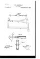
Be it known that I, GEORGE M. HARRIMAN, of South Thomaston, in the county of Knox and State of Maine, have invented Va new and Improved Saw-Frame, of which the following isla specification, reference being had to the annexed drawings, forming a part thereof, in which- Figure 1 is a side elevation of a saw frame provided with my improvement. Fig. 2 is an enlarged sectional side elevation of the pivotal connection of the brace; and Fig. 3 is an end elevation of the same.
Similar letters of reference indicate corresponding parts in all the views.
The object of my invention is to provide a saw frame in which the brace or central part will be pivotally connected with the curved end piece of the saw frame.
My invention consists in a saddle adapted to receive the shorter end piece of the saw frame and provided with trunnions, and a socket fitted to the brace or central piece of the frame and provided with a forked end for receiving the trunnions of the saddle, all as will be hereinafter more fully described.
The saw frame is provided with the usual long end piece A, furnished with the handle a, and mortises b, for receiving the forked end of the central bar or braceB; the shorter end piece A', and the straining rod C, the said rod being provided at the center with the usual turn-buckle c. The saw D is received in slots in the end pieces of the saw frame, and held by pins in the usual way. The end of the brace B adjoining the shorter end piece A of the saw frame is rounded to receive the socket E, provided with the fork d. .To the tends over the sides thereof, and on opposite sides is provided with trunnions e. The fork dembraces the saddle F, and is provided with notched extremities for receiving the trunnions e. With this construction the end piece A is provided with a pivotal bearing which allows it to tilt freely in the operation of straining the saw, without injury to the Saw frame, and the saddle F may be secured by means of a screw passing through it into the end piece A', or it may be left free to adjust itself along the length of the end piece so that it will come to a natural bearing on the inner edge of the said end piece.
The socket E, with its fork d and saddle F, is preferably made of cast metal, and it may be protected by a coating of japan, or it may be galvanized according to any of the well known methods.
Having thus described my invention, I claim as new and desire t0 secure by Letters Patent- 1. An attachment for saw frames, formed of a socket adapted to receive the end of the brace of the saw frame, and a saddle itted to an end piece of the saw frame and provided with trunnions having bearings in the fork of the socket, substantially as specified.
2. The combination, with a saw frame, of the brace B, the socket E, adapted to receive the end of the brace B, and provided with the fork d, and the saddle F, constructed to einbrace the end piece A of the frame, and provided with trunnions e having bearings in the fork d, substantially as specified.
'GEORGE M. HARRIMAN.
Witnesses:
JOHN W. WooDARD, JOSHUA P. SPALDING.
Publications (1)
| Publication Number | Publication Date |
|---|---|
| US506111A true US506111A (en) | 1893-10-03 |
Family
ID=2574946
Family Applications (1)
| Application Number | Title | Priority Date | Filing Date |
|---|---|---|---|
| US506111D Expired - Lifetime US506111A (en) | Saw-frame |
Country Status (1)
| Country | Link |
|---|---|
| US (1) | US506111A (en) |
Cited By (1)
| Publication number | Priority date | Publication date | Assignee | Title |
|---|---|---|---|---|
| US2571385A (en) * | 1947-09-22 | 1951-10-16 | Isadore J Rocklin | Tree and log saw |
-
0
- US US506111D patent/US506111A/en not_active Expired - Lifetime
Cited By (1)
| Publication number | Priority date | Publication date | Assignee | Title |
|---|---|---|---|---|
| US2571385A (en) * | 1947-09-22 | 1951-10-16 | Isadore J Rocklin | Tree and log saw |
Similar Documents
| Publication | Publication Date | Title |
|---|---|---|
| US475020A (en) | Adjustable saddle-bar for bicycles | |
| US506111A (en) | Saw-frame | |
| US565478A (en) | Stirrup | |
| US426638A (en) | Belt rest | |
| US522523A (en) | Window-guard | |
| US201444A (en) | Improvement in fastening the ends of band-saws | |
| US238190A (en) | Whiffletree for plows | |
| US508975A (en) | Reversible saw-handle | |
| US191799A (en) | Improvement in gang-saw gages | |
| US119133A (en) | Improvement in carpenters planes | |
| US877886A (en) | Riding-spur. | |
| US542577A (en) | Anton w | |
| US281627A (en) | Half to the j | |
| US88489A (en) | Improved trace-buckle | |
| US710633A (en) | Swing. | |
| US66430A (en) | Hiram l | |
| US467622A (en) | Vehicle-tongue | |
| US996185A (en) | Oscillating means for gang-saws. | |
| US85926A (en) | Improvement in pitmen | |
| US495731A (en) | Saw attachment | |
| US74427A (en) | Joseph eidee | |
| US208411A (en) | Improvement in scroll-sawing machines | |
| US480697A (en) | Butcher s or bow saw | |
| US579235A (en) | Truss | |
| US259482A (en) | Gag-runner |