US5058803A - Carton with over center toggle action indicating tab - Google Patents
Carton with over center toggle action indicating tab Download PDFInfo
- Publication number
- US5058803A US5058803A US07/634,713 US63471390A US5058803A US 5058803 A US5058803 A US 5058803A US 63471390 A US63471390 A US 63471390A US 5058803 A US5058803 A US 5058803A
- Authority
- US
- United States
- Prior art keywords
- tab
- fold line
- cuts
- carton
- common fold
- Prior art date
- Legal status (The legal status is an assumption and is not a legal conclusion. Google has not performed a legal analysis and makes no representation as to the accuracy of the status listed.)
- Expired - Lifetime
Links
- 230000009471 action Effects 0.000 title claims abstract description 24
- 239000000463 material Substances 0.000 claims abstract description 23
- 230000002093 peripheral effect Effects 0.000 claims abstract description 14
- 230000006872 improvement Effects 0.000 claims description 3
- 230000000007 visual effect Effects 0.000 claims description 3
- 239000003292 glue Substances 0.000 description 11
- 235000015220 hamburgers Nutrition 0.000 description 7
- 235000013410 fast food Nutrition 0.000 description 5
- 241000219198 Brassica Species 0.000 description 3
- 235000003351 Brassica cretica Nutrition 0.000 description 3
- 235000003343 Brassica rupestris Nutrition 0.000 description 3
- 239000000853 adhesive Substances 0.000 description 3
- 230000001070 adhesive effect Effects 0.000 description 3
- QKSKPIVNLNLAAV-UHFFFAOYSA-N bis(2-chloroethyl) sulfide Chemical compound ClCCSCCCl QKSKPIVNLNLAAV-UHFFFAOYSA-N 0.000 description 3
- 238000010276 construction Methods 0.000 description 3
- 235000010460 mustard Nutrition 0.000 description 3
- 241000234282 Allium Species 0.000 description 2
- 235000002732 Allium cepa var. cepa Nutrition 0.000 description 2
- 239000000654 additive Substances 0.000 description 2
- 235000021110 pickles Nutrition 0.000 description 2
- 230000008859 change Effects 0.000 description 1
- 235000013305 food Nutrition 0.000 description 1
- 238000000034 method Methods 0.000 description 1
- 238000012986 modification Methods 0.000 description 1
- 230000004048 modification Effects 0.000 description 1
- 239000011087 paperboard Substances 0.000 description 1
- 239000002985 plastic film Substances 0.000 description 1
- 230000000717 retained effect Effects 0.000 description 1
- 235000015067 sauces Nutrition 0.000 description 1
- 238000013022 venting Methods 0.000 description 1
Images

Classifications
-
- B—PERFORMING OPERATIONS; TRANSPORTING
- B65—CONVEYING; PACKING; STORING; HANDLING THIN OR FILAMENTARY MATERIAL
- B65D—CONTAINERS FOR STORAGE OR TRANSPORT OF ARTICLES OR MATERIALS, e.g. BAGS, BARRELS, BOTTLES, BOXES, CANS, CARTONS, CRATES, DRUMS, JARS, TANKS, HOPPERS, FORWARDING CONTAINERS; ACCESSORIES, CLOSURES, OR FITTINGS THEREFOR; PACKAGING ELEMENTS; PACKAGES
- B65D5/00—Rigid or semi-rigid containers of polygonal cross-section, e.g. boxes, cartons or trays, formed by folding or erecting one or more blanks made of paper
- B65D5/42—Details of containers or of foldable or erectable container blanks
- B65D5/4212—Information or decoration elements, e.g. content indicators, or for mailing
- B65D5/4216—Cards, coupons or the like formed integrally with, or printed directly on, the container or lid
-
- B—PERFORMING OPERATIONS; TRANSPORTING
- B65—CONVEYING; PACKING; STORING; HANDLING THIN OR FILAMENTARY MATERIAL
- B65D—CONTAINERS FOR STORAGE OR TRANSPORT OF ARTICLES OR MATERIALS, e.g. BAGS, BARRELS, BOTTLES, BOXES, CANS, CARTONS, CRATES, DRUMS, JARS, TANKS, HOPPERS, FORWARDING CONTAINERS; ACCESSORIES, CLOSURES, OR FITTINGS THEREFOR; PACKAGING ELEMENTS; PACKAGES
- B65D5/00—Rigid or semi-rigid containers of polygonal cross-section, e.g. boxes, cartons or trays, formed by folding or erecting one or more blanks made of paper
- B65D5/42—Details of containers or of foldable or erectable container blanks
- B65D5/64—Lids
- B65D5/66—Hinged lids
- B65D5/6626—Hinged lids formed by folding extensions of a side panel of a container body formed by erecting a "cross-like" blank
Definitions
- This invention relates to sheet material products and more particularly to improvements in such sheet material products relating to exterior designation or vent holes.
- Paperboard and plastic sheets have been used to make hamburger cartons and other sandwich packages. In many such uses, it is desirable to be able to designate on the exterior of the carton, the specific characteristics of the product contained therein, especially where the product may take any one of several different forms.
- An example of such designations is in hamburger cartons where the contained hamburger may be made with various different spreads and additives.
- a typical method of designation has been to provide a number of designated boxes, such as ⁇ pickles, ⁇ onions, ⁇ relish, ⁇ mustard, ⁇ catsup, ⁇ mayo, ⁇ sauce which are then specifically identified either by adding marks or in some instances removing punch-out tabs.
- An object of the present invention is to fulfill the above-described need.
- this objective is obtained by providing in a sheet material structure having two wall portions integrally interconnected by a common fold line and disposed so as to extend from said common fold line in angular relation with respect to one another to thereby define an interior included angle therebetween of less than 180° an improvement which comprises delineations defining the peripheral edges of an over center toggle action tab which extends into the two wall portions and contains a predetermined length of the common fold line which serves to divide the tab into two tab sections.
- the delineations include cuts and edge lines formed in the wall portions enabling the peripheral edge portion of the tab defined by the cuts to move toward and away from the adjacent cut wall portions while the peripheral edge portions of the tab defined by the edge lines hinge with respect to the adjacent wall portions.
- the over center toggle action tab is self-retained in a normal position wherein the two tab sections are coplanar with the two wall portions so as to define an interior included angle therebetween which is the same as the interior included angle between the two wall portions and is movable from the normal position by inward digital pressure on the predetermined length of the common fold line into a self-retained deflected position wherein the interior included angle between the two tab sections is greater than 180°.
- one of the tab sections is of a lesser size than the other such that the one tab section is relatively rigid and the other tab section is relatively flexible whereby during the movement thereof between the normal and deflected positions the other relatively flexible tab section is flexed by the relatively rigid one tab section.
- the cover structure includes a top wall having a periphery defined by a series of straight edges and a plurality of side walls folded from a plurality of the straight edges of said top wall. Each side wall extends from the top wall along an associated top wall straight edge constituting a common fold line therebetween within a plane defining an interior included angle with the top wall of less than 180°.
- the cover structure includes delineations defining a plurality of over center toggle action tabs, each of which extends within the top wall and an interconnected side wall and contains a predetermined length of the common fold line therebetween which serves to divide the tab into two tab sections.
- Indicia is provided on the carton material in operative association with each tab so as to give a visual indication distinctive thereto indicative of a distinctive product received in the erected carton.
- the delineations defining each over center toggle action tab including cuts and edge lines formed in the top and side walls enabling the peripheral edge portion of the tab defined by the cuts to move toward and away from the adjacent cut top and side walls while the peripheral edge portions of the tab defined by said edge lines hinge with respect to the adjacent top and side walls.
- Each over center toggle action tab is self-retained in a normal position wherein the two tab sections are coplanar with the top and side walls so as to define an interior included angle therebetween which is the same as the interior included angle between the top and side walls and being movable from the normal position by inward digital pressure on the predetermined length of the common fold line therebetween into a self-retained deflected position wherein the interior included angle between the two tab sections is greater than 180°.
- Another object of the present invention is the provision of a flat carton blank for forming the carton cover structure which is simple in construction easy to erect and effective in operation.
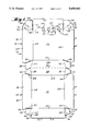
- FIG. 1 is a top plan view of a cut and scored flat blank of carton material embodying the principles of the present invention
- FIG. 2 is a perspective view of a carton erected from the blank shown in FIG. 1;
- FIG. 3 is a sectional view taken along the line 3--3 of FIG. 2;
- FIG. 4 is an enlarged fragmentary sectional view taken along the line 4--4 of FIG. 2;
- FIG. 5 is a fragmentary perspective view similar to FIG. 1 showing another form of the present invention.
- FIG. 6 is a fragmentary perspective view of a snap-action tab embodied in the carton shown in FIG. 5;
- FIG. 7 is an enlarged fragmentary sectional view taken along the line 7--7 of FIG. 5.
- FIG. 1 there is shown in FIG. 1 thereof one form of a one-piece flat blank of carton material, generally indicated at 10, embodying the principles of the present invention, which is operable to be erected and retained by adhesive into an easy close - easy open carton, generally indicated at 12, shown in FIGS. 2-5, which also embodies the principles of the present invention.
- the present invention is particularly concerned with the provision of structure built into the carton which serves the purpose of venting the interior thereof and/or indicating the specific nature of the contents of the carton 12.
- the invention also contemplates the provision of structure to provide these functions in other related devices made of sheet material having two angularly related panels.
- the construction of the carton 12 itself is exemplary only.
- the carton is of the easy-close easy-open type such as disclosed in commonly assigned U. S. patent application No. 07/625181 filed Dec. 10, 1990, entitled “Closable Carton with Improved Snap Action Lock", the disclosure of which is hereby incorporated by reference into the present specification.
- the flat blank 10 includes a tray section, generally indicated at 14, and a cover section, generally indicated at 16, the two sections being hingedly connected together.
- the tray section 14 includes a bottom wall 18 which is defined peripherally by a plurality of straight edges, including a front edge 20, a rearward edge 22, and left and right edges 24.
- the tray section 14 also includes a plurality of side walls which are hinged to the bottom wall along the straight edges thereof including a front side wall 26, rearward side wall 28, and left and right side walls 30.
- the front side wall 26 is defined peripherally by an inner side edge which is common with the front edge 20 of the bottom wall 18, an outer side edge 32 which is a free edge and opposite end edges 34.
- Rearward side wall 28 is defined peripherally by an inner side edge which is common with the rearward edge 22 of the bottom wall 18, an outer side edge 36 and opposite end edges 38.
- Left and right side walls 30 are defined peripherally by inner side edges which are common with the left and right edges 24 of the bottom wall 18, outer side edges 40, forward end edges 42 and rearward end edges 44.
- the opposite end edges 34 of the front side wall 26 define fold lines for integral flaps divided by diagonal fold lines 46 so as to form inner corner walls 48 and outer glue tabs 50.
- a second pair of flaps providing glue tabs 52 are hinged to the end edges 38 of the rear side wall 28.
- the four glue tabs provide means for maintaining the tray section 14 in an erected position wherein the side walls 26, 28 and 30 extend upwardly and outwardly from the bottom wall 18 so that the outer edges 32, 36 and 40 of the side walls define an open top of a tray structure, generally indicated at 54.
- the glue tabs 50 and 52 are suitably glued by a suitable adhesive or glue to the adjacent interior surface of the left and right side walls 30.
- the cover section 16 includes a top wall 56 which is of similar configuration to the bottom wall 18, being defined peripherally by front, rearward and left and right corresponding straight edges 58, 60, and 62 respectively.
- the cover section includes front, rearward and left and right side walls 64, 66, and 68, respectively, which are hinged to the top wall 56 along the straight edges 58, 60, and 62 respectively thereof.
- the front side wall 64 is defined peripherally by an inner side edge defined by the front edge 58 of the top wall 56, an outer side edge 70 and a pair of opposite end edges 72 extending therebetween.
- the rearward side wall 66 is defined peripherally by an inner side edge common with the rear edge 60 of the top wall 56, an outer side edge common with the outer side edge 36 of the rear side wall 28 of the tray section 14 and opposite end edges 74.
- the left and right side walls 68 are defined peripherally by inner side edges common with the left and right edges 62 of the top wall 56, outer side edges 76, front end edges 78, and rearward end edges 80.
- the end edges 74 of the rearward cover side wall 66 define fold lines for flaps providing glue tabs 82 which are hinged thereto along the fold lines.
- the front end edges 78 of the left and right side walls 68 are defined by straight fold lines which serve to join integral flaps having diagonal fold lines 84 therein which serve to divide the flaps into inner corner walls 86 and outer glue tabs 88.
- the four glue tabs 82 and 88 serve to retain the cover section 16 in an erected condition defining a cover structure, generally indicated at 90.
- a suitable glue or adhesive is utilized to retain the cover structure 90 in erected condition.
- the glue tabs 82 are suitably glued to the adjacent interior surfaces of the left and right side walls 68 and the glue tabs 88 are glued to the adjacent interior surface of the front side wall 64.
- the erected carton 12 In its initial use at the fast food establishment, the erected carton 12 is held in an open position wherein the bottom wall 18 and top wall 56 are disposed generally in the same plane so that the cover structure 90 is disposed in an open position providing access to the open top of the tray structure 54. In this position, the tray side walls 26, 28, and 30 extend upwardly and outwardly from the bottom wall 18 and the cover side walls 64, 66, and 68 likewise extend upwardly and outwardly from the top wall 56.
- the carton 12 is thus in a condition to enter into a nested and stacked relationship with a multiplicity of similar cartons 12 in a similar open position, which is the usual relationship in which the carton is held in the fast food establishment.
- the common outer side edges 36 of the rear side walls 28 and 66 provide a hinge about which the cover structure 90 can be moved from its open position into a closed position, as shown in FIGS. 2-4, wherein the front side wall 64, corner walls 86, and the left and right side walls 68 of the cover structure 90 extend downwardly and outwardly of the upper edges of the front side wall 26, corner walls 48, and left and right side walls 30 of the bottom tray structure 54.
- means is provided in the carton blank 10 for releasably locking the cover structure 90 in its closed position with respect to the bottom tray structure 54.
- This means preferably includes openings 92 formed in the corner walls 86 respectively of the cover structure 90, tabs 94 defined by bulges in the outer portions of the forward end edges 42 of the left and right tray side walls 30 and tabs 96 defined by bulges in the outer portions of the opposite end edges 34 of the front side wall 26 outwardly of the inner fold lines defined thereby.
- the cover structure 90 is simply hinged about the hinge line defined by the edge 36 until it reaches a position generally overlying the tray structure 54.
- a suitable product as, for example, fast food, such as a hamburger or the like
- the cover structure 90 is simply hinged about the hinge line defined by the edge 36 until it reaches a position generally overlying the tray structure 54.
- the front side wall 64, the left and right side walls 68 and the corner walls 86 of the cover structure 90 extend downwardly and outwardly beyond the open top of the tray structure 54.
- the corner walls 86 include interior surfaces disposed below the openings 92 which are in a position to be engaged by the tabs 94 and 96 as the cover structure 90 is pressed downwardly after the aforesaid interengagement.
- the present invention is more particularly concerned with the provision of structure in the carton 12 and more particularly the cover structure 90 thereof which preferably provides the function of selectively designating the specific contents of the carton.
- the structure is in the form of a series of over center toggle action tabs, each of which is generally indicated at 100, and a series of distinctive indicia associated with each of the tabs.
- there are four tabs 100 and the four distinctive indicia are mustard 102, catsup 104, pickle 106, and onion 108.
- the tabs 100 are formed in the front cover side wall 64 and top cover wall 56 along the common edge 58 and the indicia is on the top cover wall 56 adjacent the tabs. It will be understood that the tabs and indicia may be positioned in other convenient locations in accordance with the principles hereinafter enunciated.
- each tab 100 is defined peripherally in part by a first pair of cuts 110 spaced along the common edge 58 extending into the top cover wall 56 and by a second pair of cuts 112 extending from the edge 58 at the ends of cuts 110 thereon into the front cover side wall 64.
- the remaining periphery of each tab 110 is defined by a fold line 114 in the top cover wall 56 extending between the ends of the cuts 110 therein and a fold line 116 in the front cover side wall 64 extending between the ends of the cuts 112 therein. It will be noted that the portion of the common edge 58 extending between the aligned ends of the cuts 110 and 112 serves to divide the associated tab 100 into two tab portions 118 and 120.
- one of the tab portions is larger than the other.
- This relationship is advantageous in that it materially aids in accomplishing the over center toggle action which takes place when a tab 100 is manually moved from a normal position wherein the two tab portions 118 and 120 are coplanar with the top cover wall 56 and front cover side wall 64 respectively.
- the tab portions 118 and 120 like the walls 56 and 64, define an interior included angle therebetween which is less than 180° and preferably greater than 90°, such as the angle of approximately 118° shown.
- the cuts 110 and 112 allow the juncture 58 of the two tab portions 118 and 120 to be manually moved inwardly by digital pressure, which pressure tends to cause the tab portions to be compressed together between the fixed fold lines 114 and 116.
- a natural flexure or partial collapse of the larger tab portion 120 is induced together with a simple pivotal movement of the shorter tab portion about its fold line 114.
- the tab portions tend to straighten themselves on the opposite side of the aforesaid plane into a self-retained deflected position wherein the interior included angle between the two tab portions 118 and 120 is greater than 180° such as the approximately 242° angle shown.
- the action is similar to the action of an over center spring-actuated toggle linkage except that, rather than the pivot points of the links moving against and under the bias of a spring, the flexing of preferably one tab portion (or both) takes place against and under the self bias of the tab portions themselves.
- FIG. 2 illustrates the tab 100 associated with the mustard indicia 102 in its deflected position and tab 100 associated with the catsup indicia 104 being moved into its deflected position by digital pressure.
- the carton 12 is to receive fast food in the form of a hamburger. If the hamburger placed in the carton has added to it one or more of the additives indicated by the indicia 102, 104, 106, and 108, the operator simply moves the associated tab from its normal position into its deflect position. In the event that a tab is mistakenly moved, it is a simple matter for the operator to lift the cover structure 90 so as to obtain interior access to the tab and then to digitally push the tab 100 back into its normal position.
- the user simply moves the cover structure 90 from its closed position into its open position by manually engaging beneath the lower edge 70 of the front cover side wall or below the lower edges of the corner walls 86 to gain access to the indicated hamburger confined in the open tray structure 54.
- FIGS. 5, 6, and 7 illustrate a modified form of over center toggle-action tab, generally indicated at 128, which may be utilized in accordance with the principles of the present invention in lieu of the over center toggle-action tab 100.
- each tab 128 is defined peripherally in part by a cut 130 extending from the common edge 58 into the top cover wall 56 and a cut 132 extending from the edge 58 at the associated end of the cut 130 into the front cover side wall 64.
- each tab 128 is defined by a fold line 138 within the top cover wall 56 which extends from the end of the cut 130 therein diagonally to the common edge 58 at a position spaced from the position that the cut 130 extends therefrom and a fold line 136 within the front cover side panel 64 extending from the end of the cut 132 therein diagonally to the common edge 58 at the point the fold line 134 ends thereon.
- a fold line 138 within the top cover wall 56 which extends from the end of the cut 130 therein diagonally to the common edge 58 at a position spaced from the position that the cut 130 extends therefrom and a fold line 136 within the front cover side panel 64 extending from the end of the cut 132 therein diagonally to the common edge 58 at the point the fold line 134 ends thereon.
- each tab 128 is normally biased into a normal position wherein the tab portions are coplanar with the top cover wall 56 and front cover side wall 64 respectively into a deflected position wherein the interior included angle between the tab portions 138 and 140 is an angle greater than 180°.
- the arrangement is such that the tab portions are self-biased into the deflected position as well.
Abstract
Description
Claims (19)
Priority Applications (1)
| Application Number | Priority Date | Filing Date | Title |
|---|---|---|---|
| US07/634,713 US5058803A (en) | 1990-12-27 | 1990-12-27 | Carton with over center toggle action indicating tab |
Applications Claiming Priority (1)
| Application Number | Priority Date | Filing Date | Title |
|---|---|---|---|
| US07/634,713 US5058803A (en) | 1990-12-27 | 1990-12-27 | Carton with over center toggle action indicating tab |
Publications (1)
| Publication Number | Publication Date |
|---|---|
| US5058803A true US5058803A (en) | 1991-10-22 |
Family
ID=24544921
Family Applications (1)
| Application Number | Title | Priority Date | Filing Date |
|---|---|---|---|
| US07/634,713 Expired - Lifetime US5058803A (en) | 1990-12-27 | 1990-12-27 | Carton with over center toggle action indicating tab |
Country Status (1)
| Country | Link |
|---|---|
| US (1) | US5058803A (en) |
Cited By (27)
| Publication number | Priority date | Publication date | Assignee | Title |
|---|---|---|---|---|
| US5205476A (en) * | 1992-06-12 | 1993-04-27 | Perseco Division Of The Havi Group Lp | Clamshell carton having an improved latching mechanism |
| WO1996038343A1 (en) * | 1995-05-29 | 1996-12-05 | ELFVIN, Björn | Beverage container and bottom closure therefore |
| US5788145A (en) * | 1996-12-23 | 1998-08-04 | Bell Paper Box, Inc. | Foldable covered food container |
| EP0896927A2 (en) * | 1997-08-13 | 1999-02-17 | Beiersdorf Aktiengesellschaft | Sales tray |
| US5947321A (en) * | 1998-01-09 | 1999-09-07 | Tenneco Packaging Inc. | Vented food container |
| US6299059B1 (en) | 2000-01-24 | 2001-10-09 | International Paper Co. | Mechanical lock for paper carton |
| US20030047595A1 (en) * | 2001-09-12 | 2003-03-13 | Field Container Co. L.P. | Paperboard box with removable identifying indicia |
| WO2003029084A2 (en) * | 2001-10-03 | 2003-04-10 | Mcdonald's Restaurants Limited | Beverage cup |
| US6685085B2 (en) * | 2002-02-08 | 2004-02-03 | Arvco Container Corporation | Tamper-resistant food container |
| US7232054B2 (en) | 2002-10-21 | 2007-06-19 | Dopaco, Inc. | Carton structure and sheet material product with indicia keys |
| US20070197863A1 (en) * | 2006-02-21 | 2007-08-23 | Little Paul K | Direct reading endoscopic measuring instrument and method |
| US20070267468A1 (en) * | 2006-05-19 | 2007-11-22 | Bradley John Burke | Container having tab identifiers and method for constructing the same |
| US20070267467A1 (en) * | 2006-05-19 | 2007-11-22 | Bradley John Burke | Container having tab identifiers and method for constructing the same |
| US20100258615A1 (en) * | 2009-04-08 | 2010-10-14 | Burrows Paper Corporation | Closure for Clamshell Package |
| US8074952B2 (en) * | 2010-04-14 | 2011-12-13 | Sonoco Development, Inc. | Truncated pyramid shaped shipping base |
| US20130193197A1 (en) * | 2012-01-30 | 2013-08-01 | OIA Global Logistics SCM, INC. | Sheet and folding method for self-latching clamshell folded box |
| US8523049B2 (en) | 2010-08-16 | 2013-09-03 | Graphic Packaging International, Inc. | Sealed clamshell carton |
| US8740050B2 (en) | 2010-12-06 | 2014-06-03 | Graphic Packaging International, Inc. | Carton with lid |
| USD762468S1 (en) * | 2014-12-03 | 2016-08-02 | Huhtamaki, Inc. | Container with lock |
| USD808090S1 (en) * | 2017-01-23 | 2018-01-16 | Russel Diehl | Pet waste scooping tool |
| US10053259B2 (en) | 2015-02-27 | 2018-08-21 | Graphic Packaging International, Llc | Construct with locking features |
| US10086972B2 (en) | 2015-06-09 | 2018-10-02 | Graphic Packaging International, Llc | Carton with locking feature |
| USD842095S1 (en) | 2017-10-10 | 2019-03-05 | Graphic Packaging International, Llc | Carton |
| US10414573B2 (en) | 2013-06-03 | 2019-09-17 | Graphic Packaging International, Llc | Container with window and microwave interactive material |
| USD878914S1 (en) | 2018-10-25 | 2020-03-24 | Huhtamaki, Inc. | Foldable clamshell carton |
| US10661940B2 (en) | 2017-09-06 | 2020-05-26 | Graphic Packaging International, Llc | Carton with at least one holder |
| US11059621B2 (en) | 2018-08-06 | 2021-07-13 | Graphic Packaging International, Llc | Container with at least one compartment |
Citations (10)
| Publication number | Priority date | Publication date | Assignee | Title |
|---|---|---|---|---|
| US3111223A (en) * | 1962-07-30 | 1963-11-19 | Union Bag Camp Paper Corp | Unitized shelf loading carton |
| US3205603A (en) * | 1964-08-28 | 1965-09-14 | Diamond Int Corp | Content identification carton |
| US3396898A (en) * | 1967-06-14 | 1968-08-13 | Fed Carton Corp | Locked container |
| US3756497A (en) * | 1971-12-13 | 1973-09-04 | J Stewart | Mailing tube |
| US4472896A (en) * | 1982-11-30 | 1984-09-25 | International Paper Company | Paperboard food carton |
| US4630733A (en) * | 1985-12-20 | 1986-12-23 | Continental Bondware, Inc. | Product indicating tab |
| US4684023A (en) * | 1986-06-25 | 1987-08-04 | Taco Bell | Content-identifying carton structure |
| US4877178A (en) * | 1989-05-04 | 1989-10-31 | Dopaco, Inc. | Paperboard foldable carton |
| US4930681A (en) * | 1988-08-18 | 1990-06-05 | Clinton Fultz | Automatic latching container having good thermal insulation |
| US4951865A (en) * | 1989-12-07 | 1990-08-28 | Dopaco, Inc. | Paperboard carton with gusset lock |
-
1990
- 1990-12-27 US US07/634,713 patent/US5058803A/en not_active Expired - Lifetime
Patent Citations (10)
| Publication number | Priority date | Publication date | Assignee | Title |
|---|---|---|---|---|
| US3111223A (en) * | 1962-07-30 | 1963-11-19 | Union Bag Camp Paper Corp | Unitized shelf loading carton |
| US3205603A (en) * | 1964-08-28 | 1965-09-14 | Diamond Int Corp | Content identification carton |
| US3396898A (en) * | 1967-06-14 | 1968-08-13 | Fed Carton Corp | Locked container |
| US3756497A (en) * | 1971-12-13 | 1973-09-04 | J Stewart | Mailing tube |
| US4472896A (en) * | 1982-11-30 | 1984-09-25 | International Paper Company | Paperboard food carton |
| US4630733A (en) * | 1985-12-20 | 1986-12-23 | Continental Bondware, Inc. | Product indicating tab |
| US4684023A (en) * | 1986-06-25 | 1987-08-04 | Taco Bell | Content-identifying carton structure |
| US4930681A (en) * | 1988-08-18 | 1990-06-05 | Clinton Fultz | Automatic latching container having good thermal insulation |
| US4877178A (en) * | 1989-05-04 | 1989-10-31 | Dopaco, Inc. | Paperboard foldable carton |
| US4951865A (en) * | 1989-12-07 | 1990-08-28 | Dopaco, Inc. | Paperboard carton with gusset lock |
Cited By (37)
| Publication number | Priority date | Publication date | Assignee | Title |
|---|---|---|---|---|
| US5205476A (en) * | 1992-06-12 | 1993-04-27 | Perseco Division Of The Havi Group Lp | Clamshell carton having an improved latching mechanism |
| WO1996038343A1 (en) * | 1995-05-29 | 1996-12-05 | ELFVIN, Björn | Beverage container and bottom closure therefore |
| US5788145A (en) * | 1996-12-23 | 1998-08-04 | Bell Paper Box, Inc. | Foldable covered food container |
| EP0896927A2 (en) * | 1997-08-13 | 1999-02-17 | Beiersdorf Aktiengesellschaft | Sales tray |
| EP0896927A3 (en) * | 1997-08-13 | 1999-05-19 | Beiersdorf Aktiengesellschaft | Sales tray |
| US5947321A (en) * | 1998-01-09 | 1999-09-07 | Tenneco Packaging Inc. | Vented food container |
| US6299059B1 (en) | 2000-01-24 | 2001-10-09 | International Paper Co. | Mechanical lock for paper carton |
| US20030047595A1 (en) * | 2001-09-12 | 2003-03-13 | Field Container Co. L.P. | Paperboard box with removable identifying indicia |
| US6681983B2 (en) * | 2001-09-12 | 2004-01-27 | Field Container Company L.P. | Paperboard box with removable identifying indicia |
| WO2003029084A2 (en) * | 2001-10-03 | 2003-04-10 | Mcdonald's Restaurants Limited | Beverage cup |
| WO2003029084A3 (en) * | 2001-10-03 | 2003-10-30 | Mcdonald S Restaurants Ltd | Beverage cup |
| US6685085B2 (en) * | 2002-02-08 | 2004-02-03 | Arvco Container Corporation | Tamper-resistant food container |
| US7232054B2 (en) | 2002-10-21 | 2007-06-19 | Dopaco, Inc. | Carton structure and sheet material product with indicia keys |
| US20070197863A1 (en) * | 2006-02-21 | 2007-08-23 | Little Paul K | Direct reading endoscopic measuring instrument and method |
| US8056799B2 (en) | 2006-05-19 | 2011-11-15 | Graphic Packaging International, Inc. | Container having tab identifiers and method for constructing the same |
| US20070267467A1 (en) * | 2006-05-19 | 2007-11-22 | Bradley John Burke | Container having tab identifiers and method for constructing the same |
| US8006893B2 (en) | 2006-05-19 | 2011-08-30 | Graphic Packaging International, Inc. | Container having tab identifiers and method for constructing the same |
| US20070267468A1 (en) * | 2006-05-19 | 2007-11-22 | Bradley John Burke | Container having tab identifiers and method for constructing the same |
| US20100258615A1 (en) * | 2009-04-08 | 2010-10-14 | Burrows Paper Corporation | Closure for Clamshell Package |
| US8146743B2 (en) | 2009-04-08 | 2012-04-03 | Burrows Paper Corporation | Closure for clamshell package |
| US8074952B2 (en) * | 2010-04-14 | 2011-12-13 | Sonoco Development, Inc. | Truncated pyramid shaped shipping base |
| US20120043445A1 (en) * | 2010-04-14 | 2012-02-23 | Sonoco Development, Inc. | Truncated pyramid shaped shipping base |
| US8317150B2 (en) * | 2010-04-14 | 2012-11-27 | Sonoco Development, Inc. | Truncated pyramid shaped shipping base |
| US8523049B2 (en) | 2010-08-16 | 2013-09-03 | Graphic Packaging International, Inc. | Sealed clamshell carton |
| US8740050B2 (en) | 2010-12-06 | 2014-06-03 | Graphic Packaging International, Inc. | Carton with lid |
| US8646680B2 (en) * | 2012-01-30 | 2014-02-11 | OIA Global Logistics SCM, INC. | Sheet and folding method for self-latching clamshell folded box |
| US20130193197A1 (en) * | 2012-01-30 | 2013-08-01 | OIA Global Logistics SCM, INC. | Sheet and folding method for self-latching clamshell folded box |
| US10414573B2 (en) | 2013-06-03 | 2019-09-17 | Graphic Packaging International, Llc | Container with window and microwave interactive material |
| USD762468S1 (en) * | 2014-12-03 | 2016-08-02 | Huhtamaki, Inc. | Container with lock |
| USD787321S1 (en) | 2014-12-03 | 2017-05-23 | Huhtamaki, Inc. | Container with lock |
| US10053259B2 (en) | 2015-02-27 | 2018-08-21 | Graphic Packaging International, Llc | Construct with locking features |
| US10086972B2 (en) | 2015-06-09 | 2018-10-02 | Graphic Packaging International, Llc | Carton with locking feature |
| USD808090S1 (en) * | 2017-01-23 | 2018-01-16 | Russel Diehl | Pet waste scooping tool |
| US10661940B2 (en) | 2017-09-06 | 2020-05-26 | Graphic Packaging International, Llc | Carton with at least one holder |
| USD842095S1 (en) | 2017-10-10 | 2019-03-05 | Graphic Packaging International, Llc | Carton |
| US11059621B2 (en) | 2018-08-06 | 2021-07-13 | Graphic Packaging International, Llc | Container with at least one compartment |
| USD878914S1 (en) | 2018-10-25 | 2020-03-24 | Huhtamaki, Inc. | Foldable clamshell carton |
Similar Documents
| Publication | Publication Date | Title |
|---|---|---|
| US5058803A (en) | Carton with over center toggle action indicating tab | |
| US5263634A (en) | Safety carton for pizza and similar articles | |
| US5332147A (en) | Buckle-proof clamshell carton | |
| KR100907977B1 (en) | Packing Carton Blank | |
| US4494689A (en) | Carryout food tray | |
| US5060851A (en) | Interlocking container for carry-out food products | |
| US3985289A (en) | Two-piece container | |
| US4856707A (en) | Container for food products | |
| US7232054B2 (en) | Carton structure and sheet material product with indicia keys | |
| US4960238A (en) | 2-piece pizza box with cut-out corners | |
| US4264031A (en) | Folding, self-locking carton with separate lid including integral handle | |
| US4804136A (en) | Container | |
| JPS61500544A (en) | ball box | |
| US4311268A (en) | Footwear box with handles | |
| US4383636A (en) | Container | |
| US4979667A (en) | Pizza tray and lid | |
| US5337950A (en) | Stackable container | |
| US6581823B1 (en) | Pastry tote with handles | |
| US5390790A (en) | Octagonal container with smooth inner bottom surface | |
| US5230463A (en) | Package including a gable-shaped top | |
| GB2204857A (en) | Case and pallet systems | |
| US6299059B1 (en) | Mechanical lock for paper carton | |
| US5332146A (en) | Right parallelepiped package including non-linear fold line | |
| US5447269A (en) | Multiple unit box and blank therefor | |
| US4266715A (en) | Carton |
Legal Events
| Date | Code | Title | Description |
|---|---|---|---|
| AS | Assignment |
Owner name: GULF STATES PAPER CORPORATION, TUSCALOOSA, ALABAMA Free format text: ASSIGNMENT OF ASSIGNORS INTEREST.;ASSIGNOR:GULLIVER, RICHARD F.;REEL/FRAME:005560/0123 Effective date: 19901212 |
|
| STCF | Information on status: patent grant |
Free format text: PATENTED CASE |
|
| FEPP | Fee payment procedure |
Free format text: PAYOR NUMBER ASSIGNED (ORIGINAL EVENT CODE: ASPN); ENTITY STATUS OF PATENT OWNER: LARGE ENTITY |
|
| FPAY | Fee payment |
Year of fee payment: 4 |
|
| FPAY | Fee payment |
Year of fee payment: 8 |
|
| FPAY | Fee payment |
Year of fee payment: 12 |
|
| AS | Assignment |
Owner name: GSPC ENTERPRISE INC., ALABAMA Free format text: ASSIGNMENT OF ASSIGNORS INTEREST;ASSIGNOR:GULF STATES PAPER CORPORATION;REEL/FRAME:013669/0278 Effective date: 20021223 |
|
| AS | Assignment |
Owner name: ROCK-TENN PACKAGING AND PAPERBOARD, LLC, GEORGIA Free format text: ASSIGNMENT OF ASSIGNORS INTEREST;ASSIGNOR:GSPC ENTERPRISES, INC.;REEL/FRAME:016360/0093 Effective date: 20050606 |
|
| AS | Assignment |
Owner name: ROCK-TENN SHARED SERVICES, LLC, GEORGIA Free format text: ASSIGNMENT OF ASSIGNORS INTEREST;ASSIGNOR:ROCK-TENN PACKAGING AND PAPERBOARD, LLC;REEL/FRAME:016263/0525 Effective date: 20050715 |
|
| AS | Assignment |
Owner name: WACHOVIA BANK, NATIONAL ASSOCIATION, AS ADMINISTRA Free format text: NOTICE OF GRANT OF SECURITY INTEREST;ASSIGNOR:ROCK-TENN SHARED SERVICES, LLC;REEL/FRAME:016580/0708 Effective date: 20050606 |
|
| AS | Assignment |
Owner name: WACHOVIA BANK, NATIONAL ASSOCIATION, AS COLLATERAL Free format text: NOTICE OF GRANT OF SECURITY INTEREST;ASSIGNOR:ROCK-TENN SHARED SERVICES, LLC;REEL/FRAME:020627/0901 Effective date: 20080305 |
|
| AS | Assignment |
Owner name: ROCK-TENN SHARED SERVICES, LLC, GEORGIA Free format text: RELEASE BY SECURED PARTY;ASSIGNOR:WELLS FARGO BANK, NATIONAL ASSOCIATION;REEL/FRAME:026413/0958 Effective date: 20110527 |