US5056078A - Load mechanism for a beam addressable information storage disk drive system - Google Patents
Load mechanism for a beam addressable information storage disk drive system Download PDFInfo
- Publication number
- US5056078A US5056078A US07/287,805 US28780588A US5056078A US 5056078 A US5056078 A US 5056078A US 28780588 A US28780588 A US 28780588A US 5056078 A US5056078 A US 5056078A
- Authority
- US
- United States
- Prior art keywords
- disk
- platform
- disk drive
- drive means
- cartridge
- Prior art date
- Legal status (The legal status is an assumption and is not a legal conclusion. Google has not performed a legal analysis and makes no representation as to the accuracy of the status listed.)
- Expired - Lifetime
Links
Images


Classifications
-
- G—PHYSICS
- G11—INFORMATION STORAGE
- G11B—INFORMATION STORAGE BASED ON RELATIVE MOVEMENT BETWEEN RECORD CARRIER AND TRANSDUCER
- G11B17/00—Guiding record carriers not specifically of filamentary or web form, or of supports therefor
- G11B17/02—Details
- G11B17/04—Feeding or guiding single record carrier to or from transducer unit
- G11B17/041—Feeding or guiding single record carrier to or from transducer unit specially adapted for discs contained within cartridges
-
- G—PHYSICS
- G11—INFORMATION STORAGE
- G11B—INFORMATION STORAGE BASED ON RELATIVE MOVEMENT BETWEEN RECORD CARRIER AND TRANSDUCER
- G11B17/00—Guiding record carriers not specifically of filamentary or web form, or of supports therefor
- G11B17/02—Details
- G11B17/022—Positioning or locking of single discs
- G11B17/028—Positioning or locking of single discs of discs rotating during transducing operation
- G11B17/0282—Positioning or locking of single discs of discs rotating during transducing operation by means provided on the turntable
-
- G—PHYSICS
- G11—INFORMATION STORAGE
- G11B—INFORMATION STORAGE BASED ON RELATIVE MOVEMENT BETWEEN RECORD CARRIER AND TRANSDUCER
- G11B17/00—Guiding record carriers not specifically of filamentary or web form, or of supports therefor
- G11B17/02—Details
- G11B17/022—Positioning or locking of single discs
- G11B17/028—Positioning or locking of single discs of discs rotating during transducing operation
- G11B17/0288—Positioning or locking of single discs of discs rotating during transducing operation by means for moving the turntable or the clamper towards the disk
-
- G—PHYSICS
- G11—INFORMATION STORAGE
- G11B—INFORMATION STORAGE BASED ON RELATIVE MOVEMENT BETWEEN RECORD CARRIER AND TRANSDUCER
- G11B19/00—Driving, starting, stopping record carriers not specifically of filamentary or web form, or of supports therefor; Control thereof; Control of operating function ; Driving both disc and head
- G11B19/20—Driving; Starting; Stopping; Control thereof
- G11B19/2009—Turntables, hubs and motors for disk drives; Mounting of motors in the drive
Definitions
- This invention relates to the field of optical beam addressable disk drive systems and more particularly to apparatus for positioning a spindle drive motor in engagement with the data disk after it has been inserted into the system.
- beam addressable information storage disk drive systems capable of fitting within the half height format of a personal computer drive bay.
- the problem of achieving this objective is aggravated somewhat by the fact that beam addressable storage disks are rigid plastic disks many times the thickness of flexible ("floppy") disks commonly used as removable storage media for personal computers.
- floppy flexible
- Such disks are generally encased in protective hard shelled cartridges that add to the bulk of the disk assembly that must be accommodated in the drive system.
- U.S. Pat. No. 4,177,491 illustrates one form of a mechanism in which a combined centering cone and drive chuck are moved axially to engage the center of a computer disk.
- the cone/chuck mechanism is moved into position on the disk hub along a lead screw formed on the outer surface of a drive spindle stationary by a friction device.
- the holding force of the friction device is overcome when the chuck engages the disk so that the spindle screw and chuck rotate together to drive the disk.
- the driving force is provided by an external motor drive engaging the outer circumference of the spindle housing.
- the disk is vertically oriented and the axial movement is horizontal, although the mechanism could just as easily be rotated 90° resulting in vertical translation of the drive chuck.
- U.S. Pat. No. 4,482,993 is another example of a mechanism used to move the drive spindle to the disk hub except that, in this case, the drive spindle is raised vertically to engage a horizontal disk.
- the spindle and spindle drive motor assembled together inside a cylindrical enclosure, are translated axially within the cylinder to the disk by an external rotating cam member acting on a follower pin attached to the spindle drive motor housing.
- Magnetic disk drives employ read/write heads that are either directly in contact the disk recording surface or ride on air and thus are not subject to this critical requirement.
- a load mechanism for a beam addressable information storage disk drive system which comprises means for receiving and holding a cartridge with an optical or magneto-optical disk therein having a central drive hub; and disk drive means, including a disk drive spindle and spindle drive motor, adapted to be translated to the cartridge for engaging the disk central hub and for rotationally driving the disk.
- the load mechanism further comprises translation means disposed on opposite sides of the disk drive means for imparting reciprocal motion of said disk drive means toward and away from the disk; and compliant spring means engaged between the disk drive means and the translation means for compliantly conveying the reciprocal movement from the translation means to the disk drive means.
- the disk drive spindle and spindle drive motor are mounted on a planar platform.
- At least two pairs of relatively stiff compliant leaf springs are mounted symmetrically with respect to the axial center of the drive spindle at opposite sides of the platform.
- the springs in each pair of springs are mounted in parallel facing relationship extending outwardly from the platform to form an elongated span therebetween.
- the translation means includes a pair of counter-rotatable cranks on each side of the platform with each crank having eccentrically mounted support arm loosely captured within the span of the leaf springs.
- the load mechanism further comprises a plurality of precision stops cooperating with the surface of the platform when in the disk engaging position to precisely position the disk during read write operation.
- FIG. 1 is a side elevation view showing in schematic form a disk drive system embodying the load mechanism of the invention.
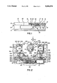
- FIG. 2 is a top plan view of that portion of the disk drive embodying a spindle lift load mechanism constructed in accordance with the invention.
- FIG. 3 is a bottom plan view of a portion of the base mount plate to which is mounted the spindle lift load mechanism of FIG. 2.
- FIG. 4 is a front perspective view, partially exploded, of the mechanism of FIG. 2.
- FIGS. 5(a)-5(c) are simplified front elevation views illustrating the load drive portion of the load mechanism of FIG. 2.
- FIGS. 6(a) and 6(b) are simplified front elevation views of the drive spindle lift portion of the load mechanism of FIG. 2.
- FIGS. 7(a) and 7(b) are simplified front elevation views of the cartridge locator pin lift portion of the load mechanism of FIG. 2.
- FIGS. 8(a) and 8(b) are partial side views of a portion of the mechanism of FIG. 2 illustrating details of the spindle lift platform support leaf springs.
- a schematic side view of an information storage disk drive system 10 of the invention includes a base enclosure 11 having an base mount plate 12 which forms a mounting base for the components of the system 10.
- An upper enclosure 13 includes provision for receiving and holding a disk cartridge 14 having nested therein a magneto-optical information storage disk 15.
- Closely spaced data tracks 16 are formed in concentric grooves on the upper planar surface of disk 15 by deposition of a recording medium comprising a thin layer of suitable thermo-magneto-optical material utilizing processes well known for this purpose.
- data tracks 16 may be "pseudo grooves" comprised of a single elongated track formed in a spiral with its center coincident with the center of disk 15.
- a drive spindle 17 is drivingly connected, at its lower end, to spindle drive motor 18 and, at its upper end, to a disk engaging chuck and centering cone assembly 19 which cooperates with a disk clamp 20 positioned above disk 15 to engage and rotationally drive the disk during read/write operation of the system 10.
- An electromagnetic bias coil 21 is held in place on upper housing 13 above disk 15 and is supplied with current from a source, not shown, to generate a concentrated magnetic field which is applied to the recording medium of the data tracks 16 as part of the magneto-optical read/write process.
- Spindle motor 18 is mounted on a platform 24 which, in accordance with the invention, is supported on a load drive mechanism mount plate 23 by means of a lift apparatus to be described in more detail subsequently.
- Load drive apparatus 22 is also housed on mount plate 23 and operates, among other things, to provide driving force to actuate the lift apparatus.
- a read/write head 25 is translatably suspended from mount plate 12 inside base enclosure 11 by means of tracking actuator apparatus which moves the head laterally (right and left as viewed in the drawing) along a drive path which is parallel to the planar surface of disk 15 and generally radial to the disk center to position and hold a focussed laser optical beam 26 generated within head 25 on a selected one of data tracks 16.
- Suitable tracking actuator apparatus for this purpose is disclosed in copending application Ser. No. 07/287,801, filed Dec. 20, 1988, entitled SINGLE STAGE TRACKING ACTUATOR APPARATUS FOR OPTICAL BEAM INFORMATION STORAGE DRIVE SYSTEM and the details are not repeated here as they are not required for an understanding of the present invention.
- a printed circuit board 27 may be positioned along the bottom of base enclosure 11 to provide necessary control functions for operation of the disk drive system.
- the spatial orientation of disk 15 be set and maintained, both statically and rotationally, as precisely as possible in relation to the position of the beam objective lens in head 25 in order to minimize the amount of focus and tracking error correction required to be applied to the objective lens focus actuator and head tracking actuator to compensate for any such mispositioning.
- the axial ("z" axis) distance between the objective lens in head 25 and the plane of data tracks 16 should be set at the focal length of the objective lens in order to avoid static misfocussing.
- the plane of rotation of the disk must be held precisely parallel with the line of travel (tracking axis) of head 25 since any tilt of disk 15 will result in dynamic misfocussing as the head traverses across the tracks putting further stress on the objective lens focus actuator in the head.
- the function of the spindle drive in positioning the disk is an important element in the successful operation of the disk drive. While it is relatively easy to accomplish this at the point of manufacture in the case of a stationary spindle drive mounted directly to the mechanism mounting, a disk drive with a movably mounted spindle drive requires careful consideration to achieve this result on a repetitive basis, each and every time a disk is inserted into the drive.
- the load mechanism of the invention includes disk drive spindle assembly 19 having a spindle 17 on which is fixed a spindle chuck 30 having a disk engaging surface 31.
- a disk centering cone 32 is mounted on spindle 17 concentrically within the disk engaging surface of the chuck and is held in place by a washer shaped steel disk 33 press fit onto spindle 17.
- a spindle drive motor 18 is drivingly engaged with spindle 17.
- the entire assembly of drive motor, centering cone and chuck is precision mounted on a horizontally disposed platform 24 held loosely in place by side mounted parallel leaf springs 41a, 41b and 42a, 42b (FIG.
- a pair of positioning holes 37a, 37b are formed in platform 24 and are adapted to slidably engage with a mating pair of positioning pins 38a, 38b which depend from the bottom surface of mount plate 12 (FIG. 6(a)).
- the diameters of pins 38a, 38b and holes 37a, 37b are selected to provide a close but non-binding fit to allow sliding axial movement of platform 24 up and down pins 38a, 38b without appreciable lateral movement of platform 24.
- a trio of precision stops 39a-39c are formed in a triangular configuration on the undersurface of mount plate 12 to accurately position the upper surface of platform 24 when the platform is raised to bring disk engaging surface of chuck 30 into engagement with disk 15.
- Precision machining of the land areas of the stops relative to the surfaces of similar mount pads used for the tracking actuator of head 25 and precision mounting of spindle assembly 19 on platform 24 are employed to assure that a correct vertical (z-axis) spacing of disk tracks 16 from the objective lens of head 25 is achieved, as well as a disk rotational plane that is parallel to the tracking axis of head 25, each time the platform is raised into its operational position.
- the mechanism for raising and lowering platform 24 includes compliant spring means, comprised of a first pair of flat, relatively stiff leaf springs 41a, 41b and a second, similar pair of leaf springs 42a, 42b, mounted on opposite sides of platform 24 by suitable means such as screws 43.
- the pairs of leaf springs are preferably mounted symmetrically on a line passing through the axial center of spindle 17.
- the springs of each pair are mounted on upper and lower surfaces of platform 24 and extend respectively outwardly from the platform to form a space or span therebetween as can best be seen in FIG. 8(b).
- Translation means for translating the platform 24 toward disk 15 includes a pair of counter-rotatable cranks 45a, 45b disposed on opposite sides of platform 24.
- the cranks have their rotational axles 46a, 46b journalled in slots in upstanding walls 47a, 47b and 48a, 48b formed on the load mechanism support plate 23.
- crank axle ends 49a, 49b are journalled in holes in walls 50a, 50b also formed on mount plate 23.
- Support arms 51a, 51b mounted eccentrically on the cranks by crank arms 52a, 52b are loosely captured in the spans between respective pairs of leaf springs 41a, 41b and 42a, 42b and provide the sole means of axial support for platform 24.
- leaf springs 42a, 42b are preferably formed with a slight bend 100 near the mounting screws as shown in FIG. 8(a) to provide a pre-load force to assure that, while the support arms are loosely captured by the springs, the fit is snug enough that there is no excess play in the mounting.
- platform 24 is extended outward by a short length 101 to hold the springs parallel against the pre-load force.
- Means for rotationally driving cranks 45a, 45b includes a reversible load drive motor 61 connected to a speed reducing gear train 62 having its final pinion gear 63 engaging the teeth of rack drive gear 64.
- Rack gear 64 is drivingly engaged to a linear load drive lever 60 by means of a drive pin 65 extending from load drive lever 60 into a mating notch at the end of rack gear 64.
- An elongated leaf spring 71 is located beneath rack 64 serving, in part, to urge the rack teeth into firm engagement with pinion gear 63.
- Load drive motor 61 operates through the gear drive just described to drive linear load drive lever 60 laterally in the left or right direction (as viewed in FIG. 2) depending on whether disk cartridge 14 is being loaded into or unloaded from disk drive system 10.
- a serpentine cam slot 80 in load drive lever 60 engages with a follower pin 81 on a flag 82 and operates to lower and raise the flag into and out of the path of an optical switch (not shown) mounted on circuit board 27 which is used to turn the drive motor 61 off at each end of the lateral travel of load drive lever 60.
- Means for laterally positioning disk cartridge 14 in upper housing 13 after the cartridge has been inserted includes a pair of cartridge positioning pins 90a and 90b having chamfered upper ends adapted to engage corresponding positioning notches 14a, 14b formed in the undersurface of the cartridge 14 (FIG. 7(b)) at the outer rear corners thereof.
- Pins 90a, b are journalled in slots 91a, and 91b at opposite ends of lift lever 92.
- Cam slots 93a and 93b are formed in lever 92 near the outer ends thereof to engage drive pins 94a and 94b mounted eccentrically on arms 53a and 53b of the rotational drive cranks.
- a pair of precision holes 95a, 95b are formed in mount plate 12 to receive positioning pins 90a, 90b for vertical translation into engagement with the notches on the cartridge.
- load drive lever 60 is connected to drive crank arms 53a, 53b by means of pivotable links 66a and 66b, respectively.
- Link 66a is connected from hole 69 in drive crank arm 53a to hole 67 in load drive lever 60 at a level below that of crank axle 46a while link 66b is connected from hole 68 in drive crank arm 53b to hole 70 in load drive lever 60 at a level above that of crank axle 46b.
- pins 66a and 66b are positioned slightly overcenter to the right of their respective drive crank arms 53a and 53b. This corresponds to the downmost position of spindle drive platform 24 resting on the lower stops 77 formed on mount plate 23 as shown in FIG. 6(a).
- a switch (not shown) which activates drive motor 61 to complete the final loading of the cartridge under power.
- motor 61 When motor 61 is activated, it operates through gear train 62 and rack 64 to force load drive lever 60 to the left in the direction of arrow 72 in FIG. 5(b).
- cartridge positioning apparatus (not shown) in upper housing 13 is driven by the drive tab 60a extending upward from load drive lever 60 through slot 80 in mount plate 11 (FIG. 3) to cause cartridge 14 to be set under power into its final position in the housing ready for engagement of the disk by spindle drive chuck 30.
- links 66a and 66b pivot over center of crank arm drive holes 67 and 68, respectively, providing an idle period during which platform 24 remains stationary on lower stops 77 while cartridge 14 is being powered into its final position.
- load drive lever 60 puts links 66a, 66b in tension with their respective arms and results in counter-rotation of cranks 45a and 45b, as indicated by arrows 74 and 76, thus raising platform support arms 51a, 51b. As the support arms are rotated upwards, they also slide inward in the spans between the pairs of parallel leaf springs 41a, 41b and 42a, 42b. This action continues until load drive lever reaches its leftmost position as shown in FIG. 5(c) at which time a flag 82 is operative in conjunction with the optical switch on circuit board 27 to deactivate load drive motor 61.
- platform 24 is shown in its lowermost position on lower stops 77. In this position, platform support arms 51a and 51b on the rotational cranks are rotated slightly below horizontal, bending lower leaf springs 41b and 42b thus exerting a positive force holding platform 24 firmly against stops 77.
- platform 24 is shown in its uppermost position with spindle chuck in engagement with disk 15. In this position, the cranks are rotated slightly above horizontal to urge the platform with a positive force against the precision stops 39a-39c thereby providing a firm support for platform 24 resistant to vibration and also assuring proper operational positioning of the spindle chuck 30, and consequently the disk 15, relative to head 25.
- Apertures 80a and 80b are formed in mount plate 12 to provide relief to allow springs 41a and 42a to flex upwards without interference with mount plate 12.
- the use of the compliant spring mounts of the invention permits the use of less costly, relatively low tolerance parts in the driving means by not requiring close tolerance precision parts to achieve and hold the desired spatial positioning of spindle chuck 30.
- FIGS. 7(a)-(b) illustrate the manner in which the pair of vertically oriented positioning pins 90a, 90b are lifted through precision locator holes 95a, 95b into upper housing 13 to provide proper lateral positioning of cartridge 14. Accordingly, as rotational cranks 53a and 53b are rotated to raise platform 24, cam drive pins 94a, 94b rise and slide in cam slots 93a, 93b to cause lever 92 to be raised conjointly with the raising of platform 24. If there is any residual mispositioning of the cartridge at the end of its powered loading phase, the chamfered ends of locator pins 90a, 90b will cause the cartridge to move laterally until properly positioned as the pins slide into the notches 14a, 14b of the cartridge.
- the timing is such that locator pins 90a, 90b reach cartridge 14 first so the cartridge positioning is completed by the time spindle assembly reaches disk 15. In this way, the disk is assured of being correctly positioned to accept the centering cone 32 on spindle chuck 30 as the cone enters the disk access aperture of the cartridge.
Abstract
Description
Claims (8)
Priority Applications (1)
| Application Number | Priority Date | Filing Date | Title |
|---|---|---|---|
| US07/287,805 US5056078A (en) | 1988-12-20 | 1988-12-20 | Load mechanism for a beam addressable information storage disk drive system |
Applications Claiming Priority (1)
| Application Number | Priority Date | Filing Date | Title |
|---|---|---|---|
| US07/287,805 US5056078A (en) | 1988-12-20 | 1988-12-20 | Load mechanism for a beam addressable information storage disk drive system |
Publications (1)
| Publication Number | Publication Date |
|---|---|
| US5056078A true US5056078A (en) | 1991-10-08 |
Family
ID=23104435
Family Applications (1)
| Application Number | Title | Priority Date | Filing Date |
|---|---|---|---|
| US07/287,805 Expired - Lifetime US5056078A (en) | 1988-12-20 | 1988-12-20 | Load mechanism for a beam addressable information storage disk drive system |
Country Status (1)
| Country | Link |
|---|---|
| US (1) | US5056078A (en) |
Cited By (22)
| Publication number | Priority date | Publication date | Assignee | Title |
|---|---|---|---|---|
| WO1993000678A1 (en) * | 1991-06-28 | 1993-01-07 | Syquest Technology, Inc. | Removable cartridge disk drive with cartridge interlocking and spindle motor telescoping mechanisms |
| US5317464A (en) * | 1991-06-28 | 1994-05-31 | Syquest Technology, Inc. | Removable cartridge disk drive with cartridge interlocking and spindle motor telescoping mechanisms |
| US5416762A (en) * | 1991-04-19 | 1995-05-16 | Sony Corporation | Improved disc cartridge and recording and/or reproducing apparatus having means for positioning a turntable and disc cartridge support structure and means for reducing vibrations |
| US5583710A (en) * | 1995-05-10 | 1996-12-10 | Iomega Corporation | Disk drive having an automatic spindle motor loading mechanism |
| US5623381A (en) * | 1992-05-18 | 1997-04-22 | Alps Electric Co., Ltd. | Disk drive |
| US5623457A (en) * | 1993-04-12 | 1997-04-22 | Sony Corporation | Photomagnetic disc drive system having a locking mechanism |
| US5815344A (en) * | 1992-02-17 | 1998-09-29 | Sony Corporation | Disc cartridge loading apparatus |
| US5815470A (en) * | 1994-08-11 | 1998-09-29 | Sony Corporation | Disc drive unit |
| US5818665A (en) * | 1996-11-26 | 1998-10-06 | Western Digital Corporation | Rotary actuator arrangement and method of manufacture |
| US5912786A (en) * | 1996-06-03 | 1999-06-15 | Iomega Corporation | Disk drive apparatus having an improved spindle motor loading mechanism |
| US6002547A (en) * | 1997-05-30 | 1999-12-14 | Iomega Corporation | Disk drive with a rotatably mounted disk drive motor |
| US6014362A (en) * | 1996-06-17 | 2000-01-11 | Samsung Electronics Co., Ltd. | Phase-shift and tilt adjustable disk player |
| US6021108A (en) * | 1995-02-06 | 2000-02-01 | Sony Corporation | Optical pickup device in recording and/reproducing apparatus |
| US6064548A (en) * | 1997-05-30 | 2000-05-16 | Iomega Corporation | Eject system for ejecting a disk cartridge from a disk drive |
| US6072666A (en) * | 1997-05-30 | 2000-06-06 | Iomega Corporation | Head retraction system for retracting the heads of a disk drive |
| US6128151A (en) * | 1997-10-29 | 2000-10-03 | Iomega Corporation | Method and a system for engaging a disk drive spindle motor with a disk cartridge |
| US6141309A (en) * | 1995-07-10 | 2000-10-31 | Fujitsu Limited | Optical memory apparatus having a supporting base with an integral, fixed optical part mounting portion |
| US6301082B1 (en) | 1997-05-30 | 2001-10-09 | Iomega Corporation | Operating system for operating an eject system and a head retraction system of a disk drive |
| WO2003073418A1 (en) * | 2002-02-26 | 2003-09-04 | Koninklijke Philips Electronics N.V. | Apparatus for reading information, supporting means for use in the apparatus and method for rotating a data carrier |
| US6738334B1 (en) | 1995-07-10 | 2004-05-18 | Fujitsu Limited | Optical memory apparatus having a base with a unitary and integral optical component mounting portion and a precision mounting surface for mounting an optical component |
| US20040205799A1 (en) * | 2000-05-31 | 2004-10-14 | Fujitsu Limited | Storage device employing replaceable storage medium |
| US20050289581A1 (en) * | 2004-06-23 | 2005-12-29 | Samsung Electro-Mechanics Co., Ltd. | Height-variable type turntable assembly and optical disk device including the same |
Citations (12)
| Publication number | Priority date | Publication date | Assignee | Title |
|---|---|---|---|---|
| US4177491A (en) * | 1977-03-01 | 1979-12-04 | International Standard Electric Corporation | Clamping device for disk-shaped memory sheets |
| GB2075741A (en) * | 1980-05-09 | 1981-11-18 | Rca Corp | Disc player having turntable height varying apparatus |
| US4482993A (en) * | 1982-04-29 | 1984-11-13 | Staar S. A. | Moving drive spindle for slot-type player apparatus |
| US4577307A (en) * | 1984-09-27 | 1986-03-18 | Storage Technology Partners Ii | Optical disk magnetic load/unload mechanism |
| US4707819A (en) * | 1985-03-06 | 1987-11-17 | Takashi Ehara | Disc driving device |
| US4723185A (en) * | 1983-09-17 | 1988-02-02 | Canon Kabushiki Kaisha | Recording and/or reproducing apparatus |
| US4730296A (en) * | 1984-10-03 | 1988-03-08 | Nippon Gakki Seizo Kabushiki Kaisha | Loading device in a disc playback device |
| US4759008A (en) * | 1986-10-02 | 1988-07-19 | Pioneer Electronic Corporation | Loading mechanism for disk player |
| US4773058A (en) * | 1986-10-27 | 1988-09-20 | Eastman Kodak Company | Disk handling system and apparatus |
| US4785365A (en) * | 1986-06-14 | 1988-11-15 | Alps Electric Co., Ltd. | Door assembly with inner shutter for closing opening for cartridge insertion in disk drive device |
| US4866693A (en) * | 1986-06-13 | 1989-09-12 | Kabushiki Kaisha Toshiba | Information processing apparatus |
| US4890276A (en) * | 1986-08-25 | 1989-12-26 | Kabushiki Kaisha Toshiba | Optical disc player |
-
1988
- 1988-12-20 US US07/287,805 patent/US5056078A/en not_active Expired - Lifetime
Patent Citations (12)
| Publication number | Priority date | Publication date | Assignee | Title |
|---|---|---|---|---|
| US4177491A (en) * | 1977-03-01 | 1979-12-04 | International Standard Electric Corporation | Clamping device for disk-shaped memory sheets |
| GB2075741A (en) * | 1980-05-09 | 1981-11-18 | Rca Corp | Disc player having turntable height varying apparatus |
| US4482993A (en) * | 1982-04-29 | 1984-11-13 | Staar S. A. | Moving drive spindle for slot-type player apparatus |
| US4723185A (en) * | 1983-09-17 | 1988-02-02 | Canon Kabushiki Kaisha | Recording and/or reproducing apparatus |
| US4577307A (en) * | 1984-09-27 | 1986-03-18 | Storage Technology Partners Ii | Optical disk magnetic load/unload mechanism |
| US4730296A (en) * | 1984-10-03 | 1988-03-08 | Nippon Gakki Seizo Kabushiki Kaisha | Loading device in a disc playback device |
| US4707819A (en) * | 1985-03-06 | 1987-11-17 | Takashi Ehara | Disc driving device |
| US4866693A (en) * | 1986-06-13 | 1989-09-12 | Kabushiki Kaisha Toshiba | Information processing apparatus |
| US4785365A (en) * | 1986-06-14 | 1988-11-15 | Alps Electric Co., Ltd. | Door assembly with inner shutter for closing opening for cartridge insertion in disk drive device |
| US4890276A (en) * | 1986-08-25 | 1989-12-26 | Kabushiki Kaisha Toshiba | Optical disc player |
| US4759008A (en) * | 1986-10-02 | 1988-07-19 | Pioneer Electronic Corporation | Loading mechanism for disk player |
| US4773058A (en) * | 1986-10-27 | 1988-09-20 | Eastman Kodak Company | Disk handling system and apparatus |
Cited By (37)
| Publication number | Priority date | Publication date | Assignee | Title |
|---|---|---|---|---|
| US5416762A (en) * | 1991-04-19 | 1995-05-16 | Sony Corporation | Improved disc cartridge and recording and/or reproducing apparatus having means for positioning a turntable and disc cartridge support structure and means for reducing vibrations |
| US5317464A (en) * | 1991-06-28 | 1994-05-31 | Syquest Technology, Inc. | Removable cartridge disk drive with cartridge interlocking and spindle motor telescoping mechanisms |
| US5535072A (en) * | 1991-06-28 | 1996-07-09 | Syquest Technology, Inc. | Removable cartridge disk drive with cartridge interlocking and spindle motor telescoping mechanisms |
| WO1993000678A1 (en) * | 1991-06-28 | 1993-01-07 | Syquest Technology, Inc. | Removable cartridge disk drive with cartridge interlocking and spindle motor telescoping mechanisms |
| US5815344A (en) * | 1992-02-17 | 1998-09-29 | Sony Corporation | Disc cartridge loading apparatus |
| US5623381A (en) * | 1992-05-18 | 1997-04-22 | Alps Electric Co., Ltd. | Disk drive |
| US5657184A (en) * | 1992-05-18 | 1997-08-12 | Alps Electric Co., Ltd. | Disk drive |
| US5623457A (en) * | 1993-04-12 | 1997-04-22 | Sony Corporation | Photomagnetic disc drive system having a locking mechanism |
| US5841752A (en) * | 1994-08-11 | 1998-11-24 | Sony Corporation | Disc drive unit |
| US5815470A (en) * | 1994-08-11 | 1998-09-29 | Sony Corporation | Disc drive unit |
| US6314076B1 (en) | 1995-02-06 | 2001-11-06 | Sony Corporation | Optical pickup device in recording and/reproducing apparatus |
| US6188661B1 (en) * | 1995-02-06 | 2001-02-13 | Sony Corporation | Recording and reproducing apparatus having elevation mechanism |
| US6272092B1 (en) | 1995-02-06 | 2001-08-07 | Sony Corporatin | Recording and reproducing apparatus with lock and release mechanism |
| US6154431A (en) * | 1995-02-06 | 2000-11-28 | Sony Corporation | Recording and reproducing apparatus |
| US6046976A (en) * | 1995-02-06 | 2000-04-04 | Sony Corporation | Disc cartridge with grooves for a recording and reproducing apparatus |
| US6021108A (en) * | 1995-02-06 | 2000-02-01 | Sony Corporation | Optical pickup device in recording and/reproducing apparatus |
| US5583710A (en) * | 1995-05-10 | 1996-12-10 | Iomega Corporation | Disk drive having an automatic spindle motor loading mechanism |
| US6738334B1 (en) | 1995-07-10 | 2004-05-18 | Fujitsu Limited | Optical memory apparatus having a base with a unitary and integral optical component mounting portion and a precision mounting surface for mounting an optical component |
| US6388972B1 (en) * | 1995-07-10 | 2002-05-14 | Fujitsu Limited | Optical memory apparatus having turn table unit mounted by a plate having an integral guide portion to a supporting base |
| US6141309A (en) * | 1995-07-10 | 2000-10-31 | Fujitsu Limited | Optical memory apparatus having a supporting base with an integral, fixed optical part mounting portion |
| US5912786A (en) * | 1996-06-03 | 1999-06-15 | Iomega Corporation | Disk drive apparatus having an improved spindle motor loading mechanism |
| US5966268A (en) * | 1996-06-03 | 1999-10-12 | Iomega Corporation | Apparatus for receiving a removable disk cartridge |
| CN1087090C (en) * | 1996-06-17 | 2002-07-03 | 三星电子株式会社 | Phase-Shift and tilt adjustable disk player |
| US6014362A (en) * | 1996-06-17 | 2000-01-11 | Samsung Electronics Co., Ltd. | Phase-shift and tilt adjustable disk player |
| US5818665A (en) * | 1996-11-26 | 1998-10-06 | Western Digital Corporation | Rotary actuator arrangement and method of manufacture |
| US6301082B1 (en) | 1997-05-30 | 2001-10-09 | Iomega Corporation | Operating system for operating an eject system and a head retraction system of a disk drive |
| US6191913B1 (en) | 1997-05-30 | 2001-02-20 | Iomega Corporation | Motor loading system for a disk drive |
| US6359756B1 (en) | 1997-05-30 | 2002-03-19 | Iomega Corporation | Disk drive having a system for protecting the read/write heads |
| US6072666A (en) * | 1997-05-30 | 2000-06-06 | Iomega Corporation | Head retraction system for retracting the heads of a disk drive |
| US6064548A (en) * | 1997-05-30 | 2000-05-16 | Iomega Corporation | Eject system for ejecting a disk cartridge from a disk drive |
| US6002547A (en) * | 1997-05-30 | 1999-12-14 | Iomega Corporation | Disk drive with a rotatably mounted disk drive motor |
| US6128151A (en) * | 1997-10-29 | 2000-10-03 | Iomega Corporation | Method and a system for engaging a disk drive spindle motor with a disk cartridge |
| US20040205799A1 (en) * | 2000-05-31 | 2004-10-14 | Fujitsu Limited | Storage device employing replaceable storage medium |
| US6951026B2 (en) | 2000-05-31 | 2005-09-27 | Fujitsu Limited | Storage device adjusting tilt angle of spindle motor against replaceable storage medium |
| WO2003073418A1 (en) * | 2002-02-26 | 2003-09-04 | Koninklijke Philips Electronics N.V. | Apparatus for reading information, supporting means for use in the apparatus and method for rotating a data carrier |
| US20050289581A1 (en) * | 2004-06-23 | 2005-12-29 | Samsung Electro-Mechanics Co., Ltd. | Height-variable type turntable assembly and optical disk device including the same |
| US7398539B2 (en) * | 2004-06-23 | 2008-07-08 | Samsung Electro-Mechanics Co., Ltd | Height-variable type turntable assembly and optical disk device including the same |
Similar Documents
| Publication | Publication Date | Title |
|---|---|---|
| US5056078A (en) | Load mechanism for a beam addressable information storage disk drive system | |
| EP0416797B1 (en) | Loading apparatus for a disc-shaped record medium | |
| EP0118626B1 (en) | Apparatus for recording and/or reading information on an optically readable disc | |
| US6590732B2 (en) | Servo track writer for magnetic disks | |
| JP2001319342A (en) | Optical pickup | |
| US4788677A (en) | Disk support mechanism in a player | |
| US6633532B1 (en) | Tilt adjusting apparatus for disk drive | |
| US6922842B2 (en) | Optical pick-up device | |
| US20050240954A1 (en) | Disk drive unit, and information recording and regeneration apparatus | |
| EP1422699B1 (en) | Method of adjusting inclination of guide shaft in recording medium drive device | |
| JP2002367299A (en) | Feed mechanism of optical pickup and disk driver | |
| EP1016082B1 (en) | Disc reproduction apparatus | |
| KR20010007329A (en) | Objective lens driving device and optical disc apparatus | |
| JPH1064096A (en) | Optical disk device | |
| JPH11175981A (en) | Tangential skew adjusting device for optical disk device | |
| JP2001357574A (en) | Magneto-optical recording and reproducing device | |
| JP2791041B2 (en) | Disk drive | |
| JPH06139585A (en) | Optical disk device | |
| JP2000011386A (en) | Optical pickup transfer device | |
| JPH076370A (en) | Optical pickup device | |
| JPH076387A (en) | Optical pickup device | |
| JPH06236636A (en) | Actuator | |
| JPH0567935U (en) | Optical disk device | |
| JPH10198991A (en) | Biaxial actuator for objective lens, and magneto-optical disk device | |
| JP2005310281A (en) | Disk unit |
Legal Events
| Date | Code | Title | Description |
|---|---|---|---|
| AS | Assignment |
Owner name: VERBATIM CORPORATION Free format text: ASSIGNMENT OF ASSIGNORS INTEREST.;ASSIGNORS:CAREY, JAMES R.;ROWDEN, DAVID L.;CHAMPAGNE, PATRICK J.;REEL/FRAME:004992/0781;SIGNING DATES FROM 19881222 TO 19881228 |
|
| AS | Assignment |
Owner name: LASERDRIVE LIMITED, A CORP. OF CA., CALIFORNIA Free format text: ASSIGNMENT OF ASSIGNORS INTEREST.;ASSIGNOR:VERBATIM CORPORATION;REEL/FRAME:005323/0242 Effective date: 19890412 |
|
| AS | Assignment |
Owner name: LITERAL CORPORATION Free format text: CHANGE OF NAME;ASSIGNOR:LASERDRIVE LTD., A CORP. OF CA;REEL/FRAME:005505/0011 Effective date: 19900213 |
|
| FEPP | Fee payment procedure |
Free format text: PAT HLDR NO LONGER CLAIMS SMALL ENT STAT AS SMALL BUSINESS (ORIGINAL EVENT CODE: LSM2); ENTITY STATUS OF PATENT OWNER: LARGE ENTITY |
|
| FEPP | Fee payment procedure |
Free format text: PAT HOLDER CLAIMS SMALL ENTITY STATUS - SMALL BUSINESS (ORIGINAL EVENT CODE: SM02); ENTITY STATUS OF PATENT OWNER: LARGE ENTITY Free format text: PAYOR NUMBER ASSIGNED (ORIGINAL EVENT CODE: ASPN); ENTITY STATUS OF PATENT OWNER: LARGE ENTITY |
|
| FPAY | Fee payment |
Year of fee payment: 4 |
|
| FEPP | Fee payment procedure |
Free format text: PAYER NUMBER DE-ASSIGNED (ORIGINAL EVENT CODE: RMPN); ENTITY STATUS OF PATENT OWNER: LARGE ENTITY Free format text: PAYOR NUMBER ASSIGNED (ORIGINAL EVENT CODE: ASPN); ENTITY STATUS OF PATENT OWNER: LARGE ENTITY |
|
| REMI | Maintenance fee reminder mailed | ||
| FP | Lapsed due to failure to pay maintenance fee |
Effective date: 19991008 |
|
| FEPP | Fee payment procedure |
Free format text: PETITION RELATED TO MAINTENANCE FEES GRANTED (ORIGINAL EVENT CODE: PMFG); ENTITY STATUS OF PATENT OWNER: LARGE ENTITY |
|
| FEPP | Fee payment procedure |
Free format text: PETITION RELATED TO MAINTENANCE FEES FILED (ORIGINAL EVENT CODE: PMFP); ENTITY STATUS OF PATENT OWNER: LARGE ENTITY |
|
| FPAY | Fee payment |
Year of fee payment: 8 |
|
| SULP | Surcharge for late payment | ||
| STCF | Information on status: patent grant |
Free format text: PATENTED CASE |
|
| PRDP | Patent reinstated due to the acceptance of a late maintenance fee |
Effective date: 20011005 |
|
| AS | Assignment |
Owner name: RESEARCH INVESTMENT NETWORK, INC., CALIFORNIA Free format text: ASSIGNMENT OF ASSIGNORS INTEREST;ASSIGNOR:POPOVICH, GEORGE;REEL/FRAME:012683/0907 Effective date: 20020117 |
|
| FEPP | Fee payment procedure |
Free format text: PAYER NUMBER DE-ASSIGNED (ORIGINAL EVENT CODE: RMPN); ENTITY STATUS OF PATENT OWNER: LARGE ENTITY Free format text: PAYOR NUMBER ASSIGNED (ORIGINAL EVENT CODE: ASPN); ENTITY STATUS OF PATENT OWNER: LARGE ENTITY |
|
| FPAY | Fee payment |
Year of fee payment: 12 |