US505035A - Display cabinet - Google Patents
Display cabinet Download PDFInfo
- Publication number
- US505035A US505035A US505035DA US505035A US 505035 A US505035 A US 505035A US 505035D A US505035D A US 505035DA US 505035 A US505035 A US 505035A
- Authority
- US
- United States
- Prior art keywords
- frames
- rack
- pointer
- case
- plate
- Prior art date
- Legal status (The legal status is an assumption and is not a legal conclusion. Google has not performed a legal analysis and makes no representation as to the accuracy of the status listed.)
- Expired - Lifetime
Links
- 239000002184 metal Substances 0.000 description 2
- 238000005452 bending Methods 0.000 description 1
- 239000011521 glass Substances 0.000 description 1
- 239000000463 material Substances 0.000 description 1
- 238000005192 partition Methods 0.000 description 1
Images

Classifications
-
- G—PHYSICS
- G09—EDUCATION; CRYPTOGRAPHY; DISPLAY; ADVERTISING; SEALS
- G09F—DISPLAYING; ADVERTISING; SIGNS; LABELS OR NAME-PLATES; SEALS
- G09F11/00—Indicating arrangements for variable information in which the complete information is permanently attached to a movable support which brings it to the display position
- G09F11/02—Indicating arrangements for variable information in which the complete information is permanently attached to a movable support which brings it to the display position the display elements being secured to rotating members, e.g. drums, spindles
- G09F11/025—Indicating arrangements for variable information in which the complete information is permanently attached to a movable support which brings it to the display position the display elements being secured to rotating members, e.g. drums, spindles the members being rotated simultaneously, each face of the member carrying a part of the sign
Definitions
- This invention relates to new and useful 1mprovements in advertising and display cablnets, especially designed for displaying the t me-tables of the various railroads, at any given point, and a description of their several routes; and consists in a certain constructlon and arrangement of parts, as hereinafter fully set forth, the essential features of whlch being pointed out in the claims.
- the object of the invention is to provide means, whereby, a series of revoluble prismat c-frames may be simultaneously actuated to dlsplay upon their various faces such matter as is desired to place thereon, and afurther' provision of a graduated-plate, having characters thereon, with which a sliding pointer isadapted to register, to indicate what matter will be displayed on the exposed faces of the frames when said pointer is brought in juxtaposltion thereto.
- Fig. 3 is a rear elevation of the mechanism within the cabinet, the top and base of which are broken away.
- Flg. 5 is an enlarged vertical cross-section through said cabinet and frame.
- Fig. 6, is an enlarged detail in perspective, of the slotted graduated plate, the sliding index or pointer, and its arresting-spring.
- A designates the case or cabinet, which may be of any desired size, and constructed of any suitable material.
- a series of vertical prismatic frames B which are mounted on vertical rods D, that pass loosely through said frames and are rigidly supported at their upper and lower ends, in the horizontal bars E, F, respectively, secured within said cabinet, as clearly shown in Figs. 3, 4 and 5.
- Said frames are made, preferably of light metal, and each face of said frames, at the corners, is provided with an inwardly projecting flange 0,, made by. bending the metal of the corners upon itself, and which formways c, on the faces of the frames, as shown at the right of Fig. 2, that receive and retain the charts or display cards, G, as shown in Fig. 1, which are placed in said ways at the top of the frame and slid down to their respective places.
- the vertical rods D near their upper ends, are provided with conical collars e, shown in Fig. 5, which are rigidly se cured to said rods and bear against the under face of the top of the frames B, whereby said frames depend from said collars and are adapted to freely revolve upon said rods.
- Attached to the bottom of the frames B is a vertical sleeve 5, that environs the rod D, and carries a pinion d at its lower end through which said rod loosely passes and which ongages with a continuous horizontal rack 1-1 common to the pinions of all of said frames.
- Said rack is mounted to slide longitudinally on the bar F and is held in place by the hearing strips or blocks f having the flange or plated that projects over the upper face of the rack, as shown in Figs. 4. and 5.
- a rodl Attached to the longitudinal center of the rack H and extending through the front of the case, is a rodl, the outer end of which lies in the slot mot the graduated plate J secured to the face of the cabinet, and is provided with a knob or handle mand a pointer 0, that registers with the graduations of the face of said plate, as the rod I is adjusted in the slot 1% by means of the handle n, to operate the rack H and revolve the series of frames B, within the cabinet, by which means all of said frames are revolved simultaneously and in unison.
- an undulating-spring K over which the rod I travels, the depressions sin said spring being arranged opposite the graduations on the plate J, so that when the rod I rides into said depressions its movement will be somewhat arrested causing the pointer to slightly hesitate in passing the corresponding graduation on said plate, as shown in Fig. 6, making it easier to stop the index at the point desired.
- One end of the spring K is rigidly secured to the bar F, as shown at o. The opposite end passes freely under a clip .2, whereby said spring may elongate as the rod I rides over its elevations.
- the cabinet has a glass front, as shown at L, against which is placed a thick mat P having openings h therein opposite each of the revolnble frames B, through which the faces of said frames are exposed, and also forming the dividing partitions u, between said frames, as shown in Figs. 1 and 2.
- the corresponding faces of the frames are provided with a seriesof dial-plates G the hands of which, in one column, indicate the time of arrival of the various trains on the road, the number and description of which also appears on the face of said plate, and the hands of the opposite column indicate the time of the departure of said trains, as shown at the right of Fig. 1.
- each face of the prismatic-frames there is a graduation for each face of the prismatic-frames, and ateach graduation is a character or charactors to indicate what matter will be displayed on the corresponding faces of the frames, when the pointer is made to register therewith, the arrangement being such, that, when the pointer is moved to register with the characters on the plate J representing the road, the time-table of which, it is desired to consult, such movement of said pointer will actuate the rack H and revolve the frames B, so that when the pointer is arrested, there will be displayed upon the outer faces of. said frames, the time-table of the road indicated by said pointer.
- the frames shown are rectangular, having four sides each, which would adapt the cabinet. provided with such frames, for the use of four roads; but if desired these frames may be triangular or polygonal in form, to present any number of faces desired. Should there. not be a sufficient number of trains, on any one road, to fill the presented faces of the series of frames, such of said faces as are not used to display the time-card, may be employed to show a map of the line of the road, or views descriptive of its points of interest and the scenery along its route, as
Landscapes
- Physics & Mathematics (AREA)
- General Physics & Mathematics (AREA)
- Engineering & Computer Science (AREA)
- Theoretical Computer Science (AREA)
- Road Signs Or Road Markings (AREA)
Description
UNTT D STATES PATENT ()FFICE.
MILLARD F. DYER, OF DETROIT, MICHIGAN, ASSIGN OR TO AUTOMATIC REGISTER COMPANY, OF SAME PLACE.
DISPLAY-CABINET.
SPECIFICATION forming part of Letters Patent No. 505,035, dated September 12, 1893. Application filed November 30, 1891. Serial No, 413,488. (No-model.)
To all whom it may concern.-
Be it known that I, MILLARD F. DYER, a clt zen of the United States, residing at Detro1t, 1n thecounty of Wayne and State of Michlgan, have invented certain new and useful Improvements in Display-Cabinets; and I do declare the following to be a full, clear, and exact description of the invention, such as will enable others skilled in the art to which 1t appertains to make and use the same, reference belng had to the accompanying drawipgs, and to the letters of reference marked 1t ereon, which form a part of this specifica- 1011. I This invention relates to new and useful 1mprovements in advertising and display cablnets, especially designed for displaying the t me-tables of the various railroads, at any given point, and a description of their several routes; and consists in a certain constructlon and arrangement of parts, as hereinafter fully set forth, the essential features of whlch being pointed out in the claims.
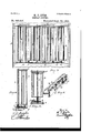
The object of the invention, is to provide means, whereby, a series of revoluble prismat c-frames may be simultaneously actuated to dlsplay upon their various faces such matter as is desired to place thereon, and afurther' provision of a graduated-plate, having characters thereon, with which a sliding pointer isadapted to register, to indicate what matter will be displayed on the exposed faces of the frames when said pointer is brought in juxtaposltion thereto. This object is attained by the mechanism illustrated in the accompanying drawings, in which- Figure l, is a front elevation of the cabinet embodying my improved features. Fig. 2, 1s an enlarged horizontal section as taken on dotted line 22 of Fig. 1, like portions belng broken away. Fig. 3, is a rear elevation of the mechanism within the cabinet, the top and base of which are broken away. Fig. 4., 1s a vertical cross section through the center of the cabinet, the prismatic-frame and its drivlng gear-wheel appearing in elevation. Flg. 5, is an enlarged vertical cross-section through said cabinet and frame. Fig. 6, is an enlarged detail in perspective, of the slotted graduated plate, the sliding index or pointer, and its arresting-spring.
Referring to the letters of reference, A, designates the case or cabinet, which may be of any desired size, and constructed of any suitable material.
Located within the cabinet are a series of vertical prismatic frames B, which are mounted on vertical rods D, that pass loosely through said frames and are rigidly supported at their upper and lower ends, in the horizontal bars E, F, respectively, secured within said cabinet, as clearly shown in Figs. 3, 4 and 5. Said frames are made, preferably of light metal, and each face of said frames, at the corners, is provided with an inwardly projecting flange 0,, made by. bending the metal of the corners upon itself, and which formways c, on the faces of the frames, as shown at the right of Fig. 2, that receive and retain the charts or display cards, G, as shown in Fig. 1, which are placed in said ways at the top of the frame and slid down to their respective places. The vertical rods D, near their upper ends, are provided with conical collars e, shown in Fig. 5, which are rigidly se cured to said rods and bear against the under face of the top of the frames B, whereby said frames depend from said collars and are adapted to freely revolve upon said rods. Attached to the bottom of the frames B, is a vertical sleeve 5, that environs the rod D, and carries a pinion d at its lower end through which said rod loosely passes and which ongages with a continuous horizontal rack 1-1 common to the pinions of all of said frames. Said rack is mounted to slide longitudinally on the bar F and is held in place by the hearing strips or blocks f having the flange or plated that projects over the upper face of the rack, as shown in Figs. 4. and 5.
Attached to the longitudinal center of the rack H and extending through the front of the case, is a rodl, the outer end of which lies in the slot mot the graduated plate J secured to the face of the cabinet, and is provided with a knob or handle mand a pointer 0, that registers with the graduations of the face of said plate, as the rod I is adjusted in the slot 1% by means of the handle n, to operate the rack H and revolve the series of frames B, within the cabinet, by which means all of said frames are revolved simultaneously and in unison.
Upon the upper face of the bar F is secured an undulating-spring K, over which the rod I travels, the depressions sin said spring being arranged opposite the graduations on the plate J, so that when the rod I rides into said depressions its movement will be somewhat arrested causing the pointer to slightly hesitate in passing the corresponding graduation on said plate, as shown in Fig. 6, making it easier to stop the index at the point desired. One end of the spring K is rigidly secured to the bar F, as shown at o. The opposite end passes freely under a clip .2, whereby said spring may elongate as the rod I rides over its elevations.
The cabinet has a glass front, as shown at L, against which is placed a thick mat P having openings h therein opposite each of the revolnble frames B, through which the faces of said frames are exposed, and also forming the dividing partitions u, between said frames, as shown in Figs. 1 and 2.
To employ this improved device as a time indicator for railway trains, the corresponding faces of the frames are provided with a seriesof dial-plates G the hands of which, in one column, indicate the time of arrival of the various trains on the road, the number and description of which also appears on the face of said plate, and the hands of the opposite column indicate the time of the departure of said trains, as shown at the right of Fig. 1. Upon the plate J there is a graduation for each face of the prismatic-frames, and ateach graduation is a character or charactors to indicate what matter will be displayed on the corresponding faces of the frames, when the pointer is made to register therewith, the arrangement being such, that, when the pointer is moved to register with the characters on the plate J representing the road, the time-table of which, it is desired to consult, such movement of said pointer will actuate the rack H and revolve the frames B, so that when the pointer is arrested, there will be displayed upon the outer faces of. said frames, the time-table of the road indicated by said pointer.
The frames shown are rectangular, having four sides each, which would adapt the cabinet. provided with such frames, for the use of four roads; but if desired these frames may be triangular or polygonal in form, to present any number of faces desired. Should there. not be a sufficient number of trains, on any one road, to fill the presented faces of the series of frames, such of said faces as are not used to display the time-card, may be employed to show a map of the line of the road, or views descriptive of its points of interest and the scenery along its route, as
shown at the left of Fig. 1, and such other matter as will be of interest to the traveler.
It is designed to place this improved cabinet in the offices of hotels, and the waiting rooms of depots, where the time-table of all roads, at that point, may be readily consulted at any time, by moving the handle n to actuate the rack,and revolve the prismatic-frames, to bring their various faces into view. I
Having thus fully set forth my invention, what I claim as new, and desire to secure by Letters Patent, is'
1. The combination of the outer case, the revoluble column located in said case, said column having a way in each of its faces, the pinion mounted on said column, the rack engaging said pinion, the movable handle at-' tached to said rack, the pointer on said handle, and the scale with which said pointer registers.
2. The combination of the case, the fixed port therein, the revoluble column, said column being located in said case in line with said port, the display matter on the several faces of said column, the' graduated plate on said case, said plate having characters-indicative of the display matter on the several faces of said column, the pinion on said column, the removable rack engaging with said pin ion, the movable handle attached to said rack, and the movable pointer that registers with said scale-plate.
3. The combinationof the case, having the fixed port therein, the vertical rodin said case, the conical collar on said rod, the revolub-le display frame, said frame loosely mounted 011 said rod adjacent to said port and supported by said collar, the pinion mounted on said frame, the sliding" rack engaging with said pinion, the movable handle attached to said rack, the scale-plate, and the movable pointer adapted to register with said late.
4. In a device for the purpose set forth, the combination of the case, the revoluble frame located therein, the pinion on said frame, the sliding rack engaging with said pinion, the handle attached to said rack and extending through the case, the undulating spring over which the stem of said handle travels,.as specified.
5. The combination of the case, having the fixed ports, the series of revoluble columns, said columns being located in said frame in horizontal alignment adjacent to said ports, thev pi-nions attached to said columns,the horizontally movable rack common to all of said pinionsand engaging therewith, the-movable hand-1e attached to said rack, the scale-plate, and the movable pointer.
6. The combination of the case, the revoluble prismatic-frames therein, said frames having a pinion at their lower-ends, the sliding rack common to and engaging with the 'pinions of all of said frames, the graduated plate on said case, the handle attached to said rack and extending through said case, said handle having a pointer that registers with the graduations on said plate, as set forth.
7. The combination of the case having a transparent face, the revoluble prismaticframes therein, said frames carrying a pinion on their lower ends, the rack common to and engaging the pinions of all of said frames, the slotted graduated plate on the front of said case, the handle attached to said rack and extending through the slot in said plate, and having a pointer that registers with the graduations thereon, as set forth.
8. The combination of the case, the revoluble prismatic-frame therein, said frame MILLARD F. DYER.
Witnesses:
SAML. HANDFORD, I. H. CLEVELAND.
Publications (1)
| Publication Number | Publication Date |
|---|---|
| US505035A true US505035A (en) | 1893-09-12 |
Family
ID=2573870
Family Applications (1)
| Application Number | Title | Priority Date | Filing Date |
|---|---|---|---|
| US505035D Expired - Lifetime US505035A (en) | Display cabinet |
Country Status (1)
| Country | Link |
|---|---|
| US (1) | US505035A (en) |
-
0
- US US505035D patent/US505035A/en not_active Expired - Lifetime
Similar Documents
| Publication | Publication Date | Title |
|---|---|---|
| NL8300858A (en) | METHOD AND APPARATUS FOR OBTAINING CITY COORDINATES. | |
| US505035A (en) | Display cabinet | |
| US1088889A (en) | Time and wage computer. | |
| US520003A (en) | Wilhelm lehnek | |
| US832871A (en) | Educational device. | |
| US3757320A (en) | Optical digital measurement readout | |
| US1973685A (en) | Computing weighing scale | |
| US1536119A (en) | Demonstrating index device | |
| US2764822A (en) | Calculating appliance | |
| US959313A (en) | Apparatus for tabulating the passenger traffic on car-lines. | |
| US798987A (en) | Railway time-indicator. | |
| US3180200A (en) | Note finder | |
| US2114417A (en) | Stereopticon slide and carrier therefor | |
| US1685790A (en) | Weighing scale | |
| US2449699A (en) | Tourist film guide | |
| US1003863A (en) | Listing-indicator. | |
| US1998027A (en) | Attendance register | |
| US408018A (en) | Electrical indicator | |
| US1541102A (en) | Herbert scott bowman | |
| US146623A (en) | Improvement in indicators | |
| US1699006A (en) | Register | |
| US728904A (en) | Calendar. | |
| US2538504A (en) | carlile | |
| US827415A (en) | Hotel-office dinkey. | |
| DE1099207B (en) | Autocollimation spectral device |