US504036A - Barrel-washer - Google Patents
Barrel-washer Download PDFInfo
- Publication number
- US504036A US504036A US504036DA US504036A US 504036 A US504036 A US 504036A US 504036D A US504036D A US 504036DA US 504036 A US504036 A US 504036A
- Authority
- US
- United States
- Prior art keywords
- barrel
- brush
- shaft
- brushes
- carrier
- Prior art date
- Legal status (The legal status is an assumption and is not a legal conclusion. Google has not performed a legal analysis and makes no representation as to the accuracy of the status listed.)
- Expired - Lifetime
Links
- 238000005406 washing Methods 0.000 description 14
- 230000007246 mechanism Effects 0.000 description 12
- 235000000396 iron Nutrition 0.000 description 8
- 238000010276 construction Methods 0.000 description 3
- 238000000034 method Methods 0.000 description 3
- 230000009471 action Effects 0.000 description 2
- 238000004140 cleaning Methods 0.000 description 2
- 230000010355 oscillation Effects 0.000 description 2
- 230000008569 process Effects 0.000 description 2
- GXCLVBGFBYZDAG-UHFFFAOYSA-N N-[2-(1H-indol-3-yl)ethyl]-N-methylprop-2-en-1-amine Chemical compound CN(CCC1=CNC2=C1C=CC=C2)CC=C GXCLVBGFBYZDAG-UHFFFAOYSA-N 0.000 description 1
- 229940000425 combination drug Drugs 0.000 description 1
- 230000000694 effects Effects 0.000 description 1
- 230000000284 resting effect Effects 0.000 description 1
- 238000005201 scrubbing Methods 0.000 description 1
- XLYOFNOQVPJJNP-UHFFFAOYSA-N water Substances O XLYOFNOQVPJJNP-UHFFFAOYSA-N 0.000 description 1
Images

Classifications
-
- B—PERFORMING OPERATIONS; TRANSPORTING
- B08—CLEANING
- B08B—CLEANING IN GENERAL; PREVENTION OF FOULING IN GENERAL
- B08B9/00—Cleaning hollow articles by methods or apparatus specially adapted thereto
- B08B9/08—Cleaning containers, e.g. tanks
- B08B9/0804—Cleaning containers having tubular shape, e.g. casks, barrels, drums
- B08B9/0808—Cleaning containers having tubular shape, e.g. casks, barrels, drums by methods involving the use of tools, e.g. by brushes, scrapers
Definitions
- This invention relates to apparatus for cleansing and washing barrels, casks or kegs, particularly barrels for malt liquors produced by breweries.
- My improvements consist in the peculiar construction of the several instrumentalities for washing and cleansing a barrel, as likewise their relation to each other in the performance of their Various functions.
- My invention is embodied in an apparatus which consists in means for holding and rotating the barrel, also in a set of reciprocating brushes, which are mounted for universal movement in order to accommodate themselves to the curvature of the barrel in both horizontal and vertical planes for the cleansing of the sides; likewise in an oscillating brush, which is to scrub the head.
- My improvements further are embodied in means by which the brush-carrier and brushes are removed or inserted in the barrel, as also in mechanism by which the brush is caused to oscillate upon the barrel head. 1 Moreover in the adjustment of parts to provide for differences in the length of the reciprocations for the side-brushes according to the varying sizes of barrels.
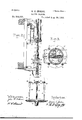
- FIG. 1 a front vertical sectional elevation of a barrel-washing machine embodying my invention.
- Fig. 2 is a side elevation of the same.
- Fig. 3 is a plan on line 3.
- Fig. 1 Fig. 4 is a central vertical section longitudinally of the plunger rod.
- Fig. 5 is a horizontal section on line 5. 5. in Fig. 4.
- Fig. 6 is a horizontal section enlarged on line 6. 6. in Fig. 4.
- FIG. 1 represents a vertical frame or support suitably positioned in an apartment,where the barrel-washing machine is to be employed. Affixed thereto are brackets 2. 2. with parallel guide-rods 3. 3. upon which are mounted cross-heads 4. 4. 4 while a connecting rod 5 from some prime motor is attached ,to the center one in order to impart reciprocations to a plunger shaft 6.
- This latter is tubular and adapted to receive a small rod 7, which extends therethrough and is furnished with a brush 8.
- This latter is mounted on a Z shaped bracket, which is pivotally secured to the lower end of the rod 7, the free end of said brush being of a shape to conform to the barrel-head and is springactuated at 9.
- a pair of reciprocating brushes or cleansing implements are employed to pass over the inside periphery of the body of the barrel.
- Said-brushes 18.18. are mounted as follows: At the lower end of the shaft 6 is a sleeve 19 affixed thereto by end of the sleeve. Transversely through the carrier-frame are positioned parallel rods 24 springactuated in order to maintain themin an extended position and so force the brushes against the inside surface of the barrel.
- the plates 25. 25 or brush-holders are united to said rods by universal joints, preferably ball and socket, and the rods, of which there are four, are diagonally employed. That is as shown in Fig.
- the rods 24 support the brushholder 25', while rods 24 perform the same duty for brush-holder 25.
- every possible movement may be assumed by the said brushes, and the latter can follow the longitudinal curvature equally with the circumferential or transverse curvature of the staves.
- the sleeve 19 is grooved and ribs 26, see Fig. 6, engage therein.
- chains or hands 27 extend from the upper part of the brush-holders 25, 25 pass about anti-friction rollers through the brushcarrier 20 by way of the holes 28, see Fig. 6, and are secured to twin-sliding bars 29. These latter are hung upon the end of a jointed lever 30 fulcrumed at 31 on a collar 32 fast on the plunger shaft.
- An actuating 1cver 34 likewise pivoted at 31 engages the bars 29, which are slotted at 35 and are guided by means of lateral studs 36, see Fig. 2.
- a spring 37 serves to take up the slack chain, as the brushes are forced toward each other owing to the curvature of the barrel staves, and which action occurs at both ends of the barrel.
- the springs 38 however overpower this spring 37 andthe brushes are normally in contact with the inside of the barrel at all times during their reciprocation.
- the brushes are first caused to approach by uplifting of the lever 34, which is held raised by means of the catch 39, the studs 36 resting in the ends of the slots 35. After this step is accomplished, the act of raising the entire brushcarrier occurs. This is effected by aid of the following mechanism: Upon the rear of the plunger shaft 4 is attached a toothed rack 40, while a pinion 41 on a small shaft 42 is controlled by a hand-wheel 43. Usually the position of the connecting rod 5 and other parts of the prime motor may be considered as fixed points to hold the crosshead 4 stationary during this act.
- springs 50 or their equivalents are employed as a counter-balance to the weight of the several cross-heads and other parts connected to them. Said springs extend from the cross-head 4 and are fastened to the bracketc in which the guide-rods are mounted. Furthermore to facilitate the cleansing of the barrel or cask distributing pipes 51 from a water supply are provided, preferably one above each of the reciprocating brushes.
- each barrel during such act is caused to revolve.
- the means which I employ for centering each barrel large or small beneath the plunger-shaft 4 and which adj ustment is necessary in order to have both the brushes do equal Work, I consider of importance and as embodying part of my invention; likewise, the mechanism for hold ing the barrels fast after they have been centered, and prior to their rotation.
- a bevel toothed pinion 53 upon a revoluble shaft in suitable bearings serves to rotate a horizontal table 54, which is formed on its under surface with a beveled toothed gear 56, while its upper surface is frusto-conical in shape, and thus the bevel approximates to that of the chine of the barrel and its construction enables small or large barrels to be centered with equal facility. After the barrel is centered it must be held rigidly in place, while the table is revolved during the process of washing. To accomplish this easily and quickly, two posts 57 are set in the table 54, diametrically opposite.
- each barrel is removed prior to washing in order to introduce the brush-carrier and brushes.
- the bracket which supports the spring 9 for the brush 8 is formed with a short horizontal arm in order to bring the vertical oifset beyond the line of the brush-carrier so as to allow the latter free reciprocations and thus enable the reciprocating brushes to traverse the entire length of the staves.
- mechanism adapted to produce yielding movement of the brush-carrier longitudinally of said shaft, substantially as specified.
- a hollow plunger-shaft means for operating the same, abrush-carrier and brushes secured upon the lower end thereof, combined with an oscil lating shaft interiorly of the plunger-shaft, and furnished with a brush at the lower end, and with mechanism at the upper end, whereby oscillations are produced by the movement of the plungershaft, substantially as set forth.
- a central brush adapted to oscillate, when the side brushes reciprocate, together with means for withdrawing said brushes from and introducing them within the barrel, and connections between said side brushes and said center brushes, whereby all are caused to operate simultaneously, substantially as stated.
- the reciprocating side brushes the brush-carrier adapted to have endwise movement upon and secured to the plunger-shaft, combined with a hollow shaft, a brush rod, longitudinally therein, reciprocating crossheads, means for operating the latter, as likewise means for oscillating the rod and composed of the forked lever, connecting-rod, and
- a plunger-shaft the interconnecting crossheads, and a brush-carrier adapted to reciprocate within a barrel, of a toothed rack secured to said shaft, a revoluble pinion mounted in one of the cross-heads, and means for looking said pinion to cause the plunger shaft to travel with said cross-head, substantially as described.
- cross-heads movable thereupon, and a plunger-shaft for variable reciprocations, a brush carrier upon said shaft, means for connecting and disconnecting one of the crossheads with the plunger-shaft, as likewise mechanism to lock and hold the cross-head fast to the guide-rods at certain times, substantially as stated.
- a brush-carrier adapted to reciprocate within a barrel, combined with brush holders, spring-impelled rods in said brush-carrier, and socket connections between said rods and the brush-holders, whereby the latter are allowed universal movement, substantially as specified.
- the combination with a plunger shaft, the brush carrier and spring-actuated brushes adapted for universal movement with respect to the carrier, of mechanism for causing the brushes to approach each other to allow their withdrawal from the barrel, substantially as herein specified.
- a barrel washing mechanism comprising vertically reciprocating brushes for the sides of the barrels, and a brush for the bottoms of the barrels, of a table provided with a projecting upper surface frusto-conical in vertical cross section and adapted to center the barrels between the brush operating mechanism, and means for rotating said table, substantially as set forth.
- the com-- bination with brush-cleaning devices and means for operating the same, of a revoluble table upon which to place a barrel, and looking mechanism composed of holding irons to grasp the barrel, and a lever and operating rods for drawing the holding irons about the staves, substantially as described.
- barrel-Washing apparatus a revoluble table, the frusto-conical upper surface, and barrel-holding mechanism, composed of the pivotal rods 59, curved holding irons 58,
Landscapes
- Engineering & Computer Science (AREA)
- Mechanical Engineering (AREA)
- Cleaning In General (AREA)
Description
1N0 Model.) I G" Sheets -Sheet BARREL WASHER. No. 504,036. Patented Aug. 29, 1893.
W dim/aw,v WM mum UNITED STATES PATENT OFFICE.
ROBERT C. INSLEE, OF BOSTON, MASSACHUSETTS.
BARREL-WASH ER.
SPECIFICATION forming part of Letters Patent No. 504,036, dated August 29, 1893.
Application filed December 30, 1892- Serial No. 456.815. (No model.)
To aZZ whom it may concern.-
Be it known that 1, ROBERT C. INSLEE, a citizen of the United States, residing at Boston, in the county of Sufiolk and State of Massachusetts, have invented certain new and useful Improvements in Barrel-Washing Machines; and I do hereby declare the following to be a full, clear, and exact description of the invention, such as will enable others skilled in the art to which it appertains to make and use the same, reference being had to the'accompanying drawings, and to figures of reference marked thereon, which form a part of this specification.
This invention relates to apparatus for cleansing and washing barrels, casks or kegs, particularly barrels for malt liquors produced by breweries.
My improvements consist in the peculiar construction of the several instrumentalities for washing and cleansing a barrel, as likewise their relation to each other in the performance of their Various functions.
My invention is embodied in an apparatus which consists in means for holding and rotating the barrel, also in a set of reciprocating brushes, which are mounted for universal movement in order to accommodate themselves to the curvature of the barrel in both horizontal and vertical planes for the cleansing of the sides; likewise in an oscillating brush, which is to scrub the head.
My improvements further are embodied in means by which the brush-carrier and brushes are removed or inserted in the barrel, as also in mechanism by which the brush is caused to oscillate upon the barrel head. 1 Moreover in the adjustment of parts to provide for differences in the length of the reciprocations for the side-brushes according to the varying sizes of barrels.
Further details of construction together with the operation of the several component parts will be hereinafter fully described and explained.
The drawings accompanying this specification represent in Figure 1 a front vertical sectional elevation of a barrel-washing machine embodying my invention. Fig. 2 is a side elevation of the same. Fig. 3 is a plan on line 3. 3. in Fig. 1. Fig. 4 is a central vertical section longitudinally of the plunger rod.
Fig. 5 is a horizontal section on line 5. 5. in Fig. 4. Fig. 6 is a horizontal section enlarged on line 6. 6. in Fig. 4.
In the said drawings 1 represents a vertical frame or support suitably positioned in an apartment,where the barrel-washing machine is to be employed. Affixed thereto are brackets 2. 2. with parallel guide-rods 3. 3. upon which are mounted cross-heads 4. 4. 4 while a connecting rod 5 from some prime motor is attached ,to the center one in order to impart reciprocations to a plunger shaft 6. This latter is tubular and adapted to receive a small rod 7, which extends therethrough and is furnished with a brush 8. This latter is mounted on a Z shaped bracket, which is pivotally secured to the lower end of the rod 7, the free end of said brush being of a shape to conform to the barrel-head and is springactuated at 9. Experimentally I find that the best effects to be derived from the use of this brush is to imitate a scrubbing or to and fro motion. Hencel have provided mechanism by which said brush is oscillated. Accordingly I have bent the upper end of the rod 7 back upon itself, as shown in Fig.4 and have secured it to a pivotal collar 10, see Fig. 2, which is at the free end of a bell-crank lever 12 attached to a sleeve loosely mounted on ashort post 13 bolted to the frame 2. To cause the rod 7 to oscillate upon movement of the plunger shaft, 2. second bell-crank lever 14 is united with the sleeve on said post 13, while a rod 15 connects the latter with a swinging lever 16. The free end of this last mentioned lever is forked and engages astud 17 which projects from one end of the crosshead 4.
In connection with the brush 8 for cleansing the barrel-head, a pair of reciprocating brushes or cleansing implements are employed to pass over the inside periphery of the body of the barrel. Said-brushes 18.18. are mounted as follows: At the lower end of the shaft 6 is a sleeve 19 affixed thereto by end of the sleeve. Transversely through the carrier-frame are positioned parallel rods 24 springactuated in order to maintain themin an extended position and so force the brushes against the inside surface of the barrel. The plates 25. 25 or brush-holders are united to said rods by universal joints, preferably ball and socket, and the rods, of which there are four, are diagonally employed. That is as shown in Fig. 4 the rods 24 support the brushholder 25', while rods 24 perform the same duty for brush-holder 25. In this way it will be seen that every possible movement may be assumed by the said brushes, and the latter can follow the longitudinal curvature equally with the circumferential or transverse curvature of the staves.
To prevent twisting or rotary movement of the bruslrcarrier, the sleeve 19 is grooved and ribs 26, see Fig. 6, engage therein.
In order to retract the brushes in case of withdrawal of the same from the cask or barrel, chains or hands 27 extend from the upper part of the brush- holders 25, 25 pass about anti-friction rollers through the brushcarrier 20 by way of the holes 28, see Fig. 6, and are secured to twin-sliding bars 29. These latter are hung upon the end of a jointed lever 30 fulcrumed at 31 on a collar 32 fast on the plunger shaft. An actuating 1cver 34 likewise pivoted at 31 engages the bars 29, which are slotted at 35 and are guided by means of lateral studs 36, see Fig. 2. Moreover a spring 37 serves to take up the slack chain, as the brushes are forced toward each other owing to the curvature of the barrel staves, and which action occurs at both ends of the barrel. The springs 38 however overpower this spring 37 andthe brushes are normally in contact with the inside of the barrel at all times during their reciprocation.
In connection with the removal of the brush-carrier and brushes from the barrel, the brushes are first caused to approach by uplifting of the lever 34, which is held raised by means of the catch 39, the studs 36 resting in the ends of the slots 35. After this step is accomplished, the act of raising the entire brushcarrier occurs. This is effected by aid of the following mechanism: Upon the rear of the plunger shaft 4 is attached a toothed rack 40, while a pinion 41 on a small shaft 42 is controlled by a hand-wheel 43. Usually the position of the connecting rod 5 and other parts of the prime motor may be considered as fixed points to hold the crosshead 4 stationary during this act. But to make a positive fixed point of leverage, I have secured a lever 46 and cams 47 loosely on the said shaft 42, in order that when the brush-carrier is to be lifted these cams are brought to bear forcibly against the guiderods 3. 3. The shaft has end thrust or movement and is furnished with a small toothed wheel 48, see Fig. 5, the duty of which is to mesh with a toothed plate 49 on the crosshead. Thus after having raised the brush carrier end the various operating elements connected therewith by rotating the shaft 42 the latter is given an endwise push. This act causes the wheel 48 to engage with the fixed tooth plate 49, and no further movement of any kind can occur, it being understood, that prior to the act of raising the lnuslrca-rrier the prime motor is stopped. Conversely the act of introducing the brushcarrier and brushes within the barrel is accomplished by giving the shaft 42 an end thrust in order to disengage the wheel 48 from the plate 49, when the shaftand pinion 41 are free to revolve.
As a counter-balance to the weight of the several cross-heads and other parts connected to them, springs 50 or their equivalents are employed. Said springs extend from the cross-head 4 and are fastened to the bracketc in which the guide-rods are mounted. Furthermore to facilitate the cleansing of the barrel or cask distributing pipes 51 from a water supply are provided, preferably one above each of the reciprocating brushes.
In order to subject every part of the interior surface of the barrel to the influence of the brushes, so as to thoroughly cleanse and sweeten the same, and to expedite the process of cleaning, each barrel during such act is caused to revolve. The means which I employ for centering each barrel large or small beneath the plunger-shaft 4 and which adj ustment is necessary in order to have both the brushes do equal Work, I consider of importance and as embodying part of my invention; likewise, the mechanism for hold ing the barrels fast after they have been centered, and prior to their rotation. These several elements, their functions and relation to each other I will now fully explain.
A bevel toothed pinion 53 upon a revoluble shaft in suitable bearings serves to rotate a horizontal table 54, which is formed on its under surface with a beveled toothed gear 56, while its upper surface is frusto-conical in shape, and thus the bevel approximates to that of the chine of the barrel and its construction enables small or large barrels to be centered with equal facility. After the barrel is centered it must be held rigidly in place, while the table is revolved during the process of washing. To accomplish this easily and quickly, two posts 57 are set in the table 54, diametrically opposite. Furthermore holding irons 58, 58, the middle portions of which are curved to approximate in shape somewhat to the body of the barrel and grasp large or small ones, are attached to uprights 59, 59', the lower ends of the latter being pivoted to the revoluble table, there being two uprights for each 'ron. This method of mounting the holding irons adapts them for barrels of all sizes, while in order to cause them to approach each other and forcibly grasp a barrel, I have pivoted a lever-bar (50 to the top of the posts 57 and united the ends of the holding irons thereto by means of connecting rods 61. Thus by forcing the pivotal points 62 past the vertical, a snap action is produced and the various parts are held locked together, the irons firmly grasping the sides of the cask.
One end head of each barrel is removed prior to washing in order to introduce the brush-carrier and brushes. In Fig. 3 the brush Sis shown as having made a partial oscillation. In Fig. 4 the bracket which supports the spring 9 for the brush 8 is formed with a short horizontal arm in order to bring the vertical oifset beyond the line of the brush-carrier so as to allow the latter free reciprocations and thus enable the reciprocating brushes to traverse the entire length of the staves.
, mechanism adapted to produce yielding movement of the brush-carrier longitudinally of said shaft, substantially as specified.
2. In combination with a reciprocating plunger shaft, and a removable extension sleeve at its lower end, a collar adapted to slide upon said sleeve, and a spring-actuated brush-carrier affixed to said collar, all operating substantially as explained.
3. In a barrel-washer, a reciprocating plunger-shaft, its cross-heads, and guides therefor, combined with abrush-carrier at its lower end, a series of movable rods transversely positioned in said carrier, and brushes affixed at the outer ends of said rods and adapted for universal movement, substantially as stated.
4. The combination with a reciprocating shaft,a brush-carrier,and brushes thereupon to operate on the staves of the barrel, of an oscillating brush adapted to operate on the barrel head, and connections between said oscillating brush and the reciprocating brushes, whereby all are caused to operate simultaneously, substantially as described.
5. In a barrel-washing machine, a hollow plunger-shaft, means for operating the same, abrush-carrier and brushes secured upon the lower end thereof, combined with an oscil lating shaft interiorly of the plunger-shaft, and furnished with a brush at the lower end, and with mechanism at the upper end, whereby oscillations are produced by the movement of the plungershaft, substantially as set forth.
6. In combination with a plunger -shaft, a
' brush-carrier, and reciprocating side brushes,
a central brush adapted to oscillate, when the side brushes reciprocate, together with means for withdrawing said brushes from and introducing them within the barrel, and connections between said side brushes and said center brushes, whereby all are caused to operate simultaneously, substantially as stated.
7. The reciprocating side brushes, the brush-carrier adapted to have endwise movement upon and secured to the plunger-shaft, combined with a hollow shaft, a brush rod, longitudinally therein, reciprocating crossheads, means for operating the latter, as likewise means for oscillating the rod and composed of the forked lever, connecting-rod, and
bell-crank levers, substantially as explained.
a plunger-shaft, the interconnecting crossheads, and a brush-carrier adapted to reciprocate within a barrel, of a toothed rack secured to said shaft, a revoluble pinion mounted in one of the cross-heads, and means for looking said pinion to cause the plunger shaft to travel with said cross-head, substantially as described. I
10. In combinationwith the fixed guides,
the cross-heads movable thereupon, and a plunger-shaft for variable reciprocations, a brush carrier upon said shaft, means for connecting and disconnecting one of the crossheads with the plunger-shaft, as likewise mechanism to lock and hold the cross-head fast to the guide-rods at certain times, substantially as stated.
11. In a washing machine, a brush-carrier adapted to reciprocate within a barrel, combined with brush holders, spring-impelled rods in said brush-carrier, and socket connections between said rods and the brush-holders, whereby the latter are allowed universal movement, substantially as specified.
12. In eombinationwith the fixed guides, the cross-heads movable thereupon, and a plunger-shaft, a brush-carrier upon said shaft, means for disconnecting and connecting one of the cross-heads with the plunger shaft, as
likewise means for raising said shaft and I brush-carrier and withdrawing them from a barrel, substantially as herein stated.
13. In a barrel-washing machine, the combination with a plunger shaft, the brush carrier and spring-actuated brushes adapted for universal movement with respect to the carrier, of mechanism for causing the brushes to approach each other to allow their withdrawal from the barrel, substantially as herein specified.
14. The combination with a barrel washing mechanism comprising vertically reciprocating brushes for the sides of the barrels, and a brush for the bottoms of the barrels, of a table provided with a projecting upper surface frusto-conical in vertical cross section and adapted to center the barrels between the brush operating mechanism, and means for rotating said table, substantially as set forth.
15. In barrel washing apparatus, the com-- bination with brush-cleaning devices, and means for operating the same, of a revoluble table upon which to place a barrel, and looking mechanism composed of holding irons to grasp the barrel, and a lever and operating rods for drawing the holding irons about the staves, substantially as described.
16. In barrel-Washing apparatus, a revoluble table, the frusto-conical upper surface, and barrel-holding mechanism, composed of the pivotal rods 59, curved holding irons 58,
. the locking lever 60 and connecting rods 61 which unite the lever with the holding irons, substantially as set forth.
17. In a barrel-washing machine, the combination with a reciprocating plunger-shaft,
Publications (1)
| Publication Number | Publication Date |
|---|---|
| US504036A true US504036A (en) | 1893-08-29 |
Family
ID=2572874
Family Applications (1)
| Application Number | Title | Priority Date | Filing Date |
|---|---|---|---|
| US504036D Expired - Lifetime US504036A (en) | Barrel-washer |
Country Status (1)
| Country | Link |
|---|---|
| US (1) | US504036A (en) |
Cited By (1)
| Publication number | Priority date | Publication date | Assignee | Title |
|---|---|---|---|---|
| US2956297A (en) * | 1958-05-05 | 1960-10-18 | R G Wright Company Inc | Brush mechanism |
-
0
- US US504036D patent/US504036A/en not_active Expired - Lifetime
Cited By (1)
| Publication number | Priority date | Publication date | Assignee | Title |
|---|---|---|---|---|
| US2956297A (en) * | 1958-05-05 | 1960-10-18 | R G Wright Company Inc | Brush mechanism |
Similar Documents
| Publication | Publication Date | Title |
|---|---|---|
| US1755763A (en) | Drum-washing machine | |
| CN111658185A (en) | Box type dental handpiece oiling machine capable of performing batch oiling treatment | |
| US966507A (en) | Barrel-washing machine. | |
| US826835A (en) | Machine for cleaning or treating printers' rollers. | |
| US2017941A (en) | Device for cleaning receptacles | |
| US1869477A (en) | Can-turning machine | |
| US1573842A (en) | Bottle-washing machine | |
| US705430A (en) | Bottle-washing machine. | |
| US682285A (en) | Can-washer. | |
| US831261A (en) | Bottle-washer. | |
| US780236A (en) | Bottle-cleaning machine. | |
| US854173A (en) | Machine for washing bottles. | |
| US716644A (en) | Bottle-washing machine. | |
| US940060A (en) | Machine for washing cans and the like. | |
| US357049A (en) | talley | |
| US1093841A (en) | Bottle-washing machine. | |
| US358163A (en) | moeeis | |
| US507330A (en) | Bottle-washer | |
| US573885A (en) | John l | |
| US772796A (en) | Bottle-washer. | |
| US794533A (en) | Bottle-washer. | |
| US354061A (en) | Machine for automatically soaking | |
| US734015A (en) | Milk-can washer. | |
| US1260329A (en) | Bottle-washing apparatus. | |
| US335068A (en) | goulding |