US5036889A - Tube with flip-top cap - Google Patents
Tube with flip-top cap Download PDFInfo
- Publication number
- US5036889A US5036889A US07/335,702 US33570289A US5036889A US 5036889 A US5036889 A US 5036889A US 33570289 A US33570289 A US 33570289A US 5036889 A US5036889 A US 5036889A
- Authority
- US
- United States
- Prior art keywords
- neck
- skirt
- frustoconical
- breast
- cap
- Prior art date
- Legal status (The legal status is an assumption and is not a legal conclusion. Google has not performed a legal analysis and makes no representation as to the accuracy of the status listed.)
- Expired - Fee Related
Links
- 210000000481 breast Anatomy 0.000 claims abstract description 24
- 229920003023 plastic Polymers 0.000 claims abstract description 17
- 239000004033 plastic Substances 0.000 claims abstract description 17
- 230000000295 complement effect Effects 0.000 claims description 3
- 230000002250 progressing effect Effects 0.000 claims description 3
- 230000001154 acute effect Effects 0.000 claims description 2
- 230000006698 induction Effects 0.000 claims description 2
- 238000007789 sealing Methods 0.000 claims description 2
- 239000011888 foil Substances 0.000 abstract description 3
- 238000003475 lamination Methods 0.000 abstract description 3
- 229910052751 metal Inorganic materials 0.000 abstract description 2
- 239000002184 metal Substances 0.000 abstract description 2
- 239000004698 Polyethylene Substances 0.000 description 2
- 229910052782 aluminium Inorganic materials 0.000 description 2
- XAGFODPZIPBFFR-UHFFFAOYSA-N aluminium Chemical compound [Al] XAGFODPZIPBFFR-UHFFFAOYSA-N 0.000 description 2
- 238000010276 construction Methods 0.000 description 2
- 239000010410 layer Substances 0.000 description 2
- 239000000463 material Substances 0.000 description 2
- -1 polyethylene Polymers 0.000 description 2
- 229920000573 polyethylene Polymers 0.000 description 2
- 238000002788 crimping Methods 0.000 description 1
- 230000009969 flowable effect Effects 0.000 description 1
- 238000002347 injection Methods 0.000 description 1
- 239000007924 injection Substances 0.000 description 1
- 238000004519 manufacturing process Methods 0.000 description 1
- 238000000465 moulding Methods 0.000 description 1
- 238000004806 packaging method and process Methods 0.000 description 1
- 238000005096 rolling process Methods 0.000 description 1
- 238000004826 seaming Methods 0.000 description 1
- 239000002356 single layer Substances 0.000 description 1
- 229940034610 toothpaste Drugs 0.000 description 1
- 239000000606 toothpaste Substances 0.000 description 1
- 238000003466 welding Methods 0.000 description 1
Images
Classifications
-
- B—PERFORMING OPERATIONS; TRANSPORTING
- B65—CONVEYING; PACKING; STORING; HANDLING THIN OR FILAMENTARY MATERIAL
- B65D—CONTAINERS FOR STORAGE OR TRANSPORT OF ARTICLES OR MATERIALS, e.g. BAGS, BARRELS, BOTTLES, BOXES, CANS, CARTONS, CRATES, DRUMS, JARS, TANKS, HOPPERS, FORWARDING CONTAINERS; ACCESSORIES, CLOSURES, OR FITTINGS THEREFOR; PACKAGING ELEMENTS; PACKAGES
- B65D35/00—Pliable tubular containers adapted to be permanently or temporarily deformed to expel contents, e.g. collapsible tubes for toothpaste or other plastic or semi-liquid material; Holders therefor
- B65D35/44—Closures
-
- B—PERFORMING OPERATIONS; TRANSPORTING
- B65—CONVEYING; PACKING; STORING; HANDLING THIN OR FILAMENTARY MATERIAL
- B65D—CONTAINERS FOR STORAGE OR TRANSPORT OF ARTICLES OR MATERIALS, e.g. BAGS, BARRELS, BOTTLES, BOXES, CANS, CARTONS, CRATES, DRUMS, JARS, TANKS, HOPPERS, FORWARDING CONTAINERS; ACCESSORIES, CLOSURES, OR FITTINGS THEREFOR; PACKAGING ELEMENTS; PACKAGES
- B65D35/00—Pliable tubular containers adapted to be permanently or temporarily deformed to expel contents, e.g. collapsible tubes for toothpaste or other plastic or semi-liquid material; Holders therefor
- B65D35/02—Body construction
- B65D35/12—Connections between body and closure-receiving bush
-
- B—PERFORMING OPERATIONS; TRANSPORTING
- B65—CONVEYING; PACKING; STORING; HANDLING THIN OR FILAMENTARY MATERIAL
- B65D—CONTAINERS FOR STORAGE OR TRANSPORT OF ARTICLES OR MATERIALS, e.g. BAGS, BARRELS, BOTTLES, BOXES, CANS, CARTONS, CRATES, DRUMS, JARS, TANKS, HOPPERS, FORWARDING CONTAINERS; ACCESSORIES, CLOSURES, OR FITTINGS THEREFOR; PACKAGING ELEMENTS; PACKAGES
- B65D47/00—Closures with filling and discharging, or with discharging, devices
- B65D47/04—Closures with discharging devices other than pumps
- B65D47/06—Closures with discharging devices other than pumps with pouring spouts or tubes; with discharge nozzles or passages
- B65D47/08—Closures with discharging devices other than pumps with pouring spouts or tubes; with discharge nozzles or passages having articulated or hinged closures
- B65D47/0804—Closures with discharging devices other than pumps with pouring spouts or tubes; with discharge nozzles or passages having articulated or hinged closures integrally formed with the base element provided with the spout or discharge passage
- B65D47/0833—Hinges without elastic bias
- B65D47/0838—Hinges without elastic bias located at an edge of the base element
Definitions
- This invention relates to a collapsible tube and, more particularly, to a collapsible tube which is made at least in part of plastic.
- Such tubes generally fall into two categories.
- the most popular in the dentrifice market is a laminate tube in which a lamination of several materials (e.g., plastic-metal-plastic) in sheet form is rolled into a tube and is longitudinally seamed.
- a plastic shoulder or breast with a threaded neck then is welded to the tube and provides a support for a closure.
- the closure may be either a simple screw-on cap or may be a screw-on fitment with a flip-top cap. In either case, the overall unit consists of three components which must be assembled with one another.
- plastic tube is injection molded from plastic and includes an integral breast with a threaded neck for supporting a closure. While a unit of this type has only two components, the plastic does not "deaden" when squeezed and thus a single layer tube is not as acceptable as a laminate tube for dispensing some products such as dentrifices.
- the general aim of the present invention is to provide a new and comparatively inexpensive laminate tube which requires only two components, namely, the tube itself and a fitment which carries a closure.
- a more detailed object of the invention is to achieve the foregoing by providing a laminate tube having an integral breast and having a plastic fitment secured to the breast and supporting an integral flip-top cap.
- the invention also resides in the unique shape of the breast and the fitment and in the construction of the flip-top cap to establish a good seal with the fitment.
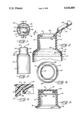
- FIG. 1 is a top plan view of a new and improved tube incorporating the unique features of the present invention.
- FIG. 2 is a fragmentary elevational view of the tube.
- FIG. 3 is an enlarged cross-section taken substantially along the line 3--3 of FIG. 1 and shows the cap of the fitment in an open position.
- FIG. 4 is a fragmentary top plan view of the fitment as seen along the line 4--4 of FIG. 3.
- FIG. 5 is a view similar to FIG. 3 but shows the cap of the fitment in a closed position.
- FIG. 6 is an enlarged view of certain parts shown in FIG. 5.
- the invention is embodied in a collapsible tube 10 for holding and dispensing a flowable product such as toothpaste.
- the tube includes an elongated cylindrical body 11 which is made by rolling a sheet into a tubular form and then seaming the sheet along its adjacent edges.
- the sheet is a lamination of different materials.
- the sheet may comprise layers of aluminum foil and paper sandwiched between layers of plastic such as polyethylene.
- the tube body 11 has a deadening characteristic meaning that the body tends to stay flat when squeezed and does not spring back to its original condition.
- a laminate tube of this type assimilates the squeeze characteristics of a metal tube and is favored for the packaging of certain products.
- the laminate tube body 11 is formed with an integral breast 12 (FIG. 3) which is bonded to a plastic closure fitment 13 having an integral flip-top cap 14.
- the overall tube unit 10 consists of only two components so as to reduce the cost of manufacturing and assembling the unit.
- the breast 12 of the tube 10 consists of a frustoconical section (see FIG. 3) which is integral with a cylindrical section defined by one end (e.g., the upper end) of the tube body 11.
- the frustoconical section 12 tapers inwardly upon progressing upwardly and its portion of smallest diameter defines the dispensing end of the body.
- the frustoconical section is formed by crimping the end portion of the body 11 inwardly after the laminated sheet has been rolled and seamed.
- the closure fitment 13 is of one-piece construction and is molded of polyethylene or other suitable plastic.
- the upper end portion of the fitment is defined by a tubular neck 15 whose inner side if substantially cylindrical. Formed integrally with and depending from the neck is an annular skirt 16.
- the skirt 16 is complementary in size and shape to the upper end portion of the tube body 11 and to the breast 12.
- the lower end portion 17 of the skirt is a cylindrical segment having an outermost side which is sized to telescope snugly into the cylindrical innermost side of the upper end portion of the body 11.
- the skirt 16 is formed with a frustoconical segment 18 of the same slope as the breast 12 and having an outermost side of the telescoped snugly into the innermost side of the breast.
- the outermost sides of the segments 17 and 18 are bonded tightly to the innermost sides of the body 11 and the breast 12, respectively, with the bonding preferably being effected by induction welding. As shown most clearly in FIG. 3, the outermost side of the breast is fully exposed.
- the skirt 16 is completed by a second frustoconical segment 19 located between the neck 15 and the frustoconical segment 18.
- the segment 19 is of shallower slope than the segment 18 and enables the neck 15 to be of relatively small diameter and to be positioned in close proximity to the breast 12.
- the segment 19 is chamfered as indicated at 20 in FIG. 3 to receive a tamper-evident insert (not shown) for sealing the product in the tube body 11.
- the cap 14 is integral with the neck 15 and is hinged on the neck to swing between an open position (FIG. 3) and a closed position (FIG. 5).
- the cap includes a flat plate 21 (FIG. 3) having one margin which is connected to the upper end of the neck 15 by a living hinge 22 (FIGS. 3 and 4) defined by a straight upwardly opening groove formed in and extending chordwise of the neck. That portion of the outside of the neck underlying the hinge is flat and vertical as indicated at 23 in FIG. 2 while the remainder of the outside of the neck is arcuate.
- annular rib 25 Formed integrally with and depending from the underside of the plate 21 is an annular rib 25 (FIGS. 3, 5 and 6) which defines a closure plug.
- the rib is adapted to coact with a fin 26 in the neck 15 to seal the neck when the cap 14 is in its closed position.
- the fin is circular, is spaced radially inwardly from the inner side of the neck, and tapers upon progressing downwardly.
- the rib 25 deflects the fin 26 as shown in FIG. 6 and seals against the fin in order to establish a good seal between the cap and the neck.
- the upper side of the plate 21 lies flush with a pair of upstanding ledges 28 (FIGS. 3 and 4) located on opposite sides of the cap and extending transversely of the hinge 22, the ledges being formed on the upper end of the neck 15.
- a thumbnail may be inserted between the ledges and beneath the free edge of the plate to facilitate lifting the cap to its open position.
- the cap 14 is molded while in an inclined position (see FIG. 3) as disclosed substantially in Foster U.S. Pat. No. 3,675,812 and is first closed after the fitment 13 has been ejected from the molding dies.
- the rib is inclined at an acute angle A (FIG. 3) of about 60 degrees relative to the underside of the plate 21.
- the present invention brings to the art a new and improved tube 10 in which the tube body 11 is laminated and is secured directly to the fitment 13 having the integral flip-top cap 14. Because the tube consists only of two components, it may be manufactured at comparatively low cost.
Landscapes
- Engineering & Computer Science (AREA)
- Mechanical Engineering (AREA)
- Tubes (AREA)
Abstract
Description
Claims (7)
Priority Applications (1)
| Application Number | Priority Date | Filing Date | Title |
|---|---|---|---|
| US07/335,702 US5036889A (en) | 1989-04-10 | 1989-04-10 | Tube with flip-top cap |
Applications Claiming Priority (1)
| Application Number | Priority Date | Filing Date | Title |
|---|---|---|---|
| US07/335,702 US5036889A (en) | 1989-04-10 | 1989-04-10 | Tube with flip-top cap |
Publications (1)
| Publication Number | Publication Date |
|---|---|
| US5036889A true US5036889A (en) | 1991-08-06 |
Family
ID=23312898
Family Applications (1)
| Application Number | Title | Priority Date | Filing Date |
|---|---|---|---|
| US07/335,702 Expired - Fee Related US5036889A (en) | 1989-04-10 | 1989-04-10 | Tube with flip-top cap |
Country Status (1)
| Country | Link |
|---|---|
| US (1) | US5036889A (en) |
Cited By (26)
| Publication number | Priority date | Publication date | Assignee | Title |
|---|---|---|---|---|
| WO1996021599A1 (en) * | 1994-11-10 | 1996-07-18 | Jebco Packaging Systems, Inc. | Fitment for flexible containers |
| FR2731983A1 (en) * | 1995-03-20 | 1996-09-27 | Momiplast Sa | Hinged cap for closing container, e.g. supple tube |
| US5690764A (en) * | 1995-02-13 | 1997-11-25 | The Procter & Gamble Company | Collapsible tube package and method of construction |
| US5775375A (en) * | 1996-06-10 | 1998-07-07 | Deere & Company | Hydraulic coupler dust cover |
| US6003556A (en) * | 1995-10-06 | 1999-12-21 | Cobe Laboratories, Inc. | Hinged cap fluid connector |
| WO2000037328A1 (en) * | 1998-12-18 | 2000-06-29 | Rigo Mihaly | Closing cap |
| US6270867B1 (en) | 1993-06-24 | 2001-08-07 | Pechiney Plastic Packaging, Inc. | Structures of polymers made from single site catalysts |
| EP1162154A1 (en) * | 2000-06-06 | 2001-12-12 | Alcan Technology & Management AG | Container with a hinged cap |
| US20060115385A1 (en) * | 2004-12-01 | 2006-06-01 | Meridian Bioscience, Inc. | Specimen collection system |
| US20060163243A1 (en) * | 2005-01-25 | 2006-07-27 | Stieler David C | Method of coupling fuel system components |
| US20060162697A1 (en) * | 2005-01-25 | 2006-07-27 | Stieler David C | Plastic coated metal fuel rail |
| US20060162144A1 (en) * | 2005-01-25 | 2006-07-27 | Stieler David C | Method of coupling fuel system components |
| US20060249213A1 (en) * | 2005-04-21 | 2006-11-09 | Stieler David C | Plastic coated metal heater and water tube assembly |
| US20070023129A1 (en) * | 2005-07-29 | 2007-02-01 | Stieler David C | Method of coupling polymeric tubing to polymeric coated metal tubing |
| US20070042148A1 (en) * | 2005-08-19 | 2007-02-22 | Stieler David C | Tether attachment to plastic coated metal tubing |
| USRE39520E1 (en) | 1998-11-19 | 2007-03-20 | Seaquist Closures Foreign, Inc. | Dispensing structure incorporating a valve-containing fitment for mounting to a container and a package with a dispensing structure |
| US20070095467A1 (en) * | 2005-10-31 | 2007-05-03 | Stieler David C | Method for joining tubular bodies with a connector |
| US20080028592A1 (en) * | 2005-09-30 | 2008-02-07 | Stieler David C | Method of coupling plastic components to metal tubing |
| WO2008047412A1 (en) * | 2006-10-17 | 2008-04-24 | Hiroshi Yoshihara | Integrally molded hinge cap |
| WO2008055961A1 (en) | 2006-11-09 | 2008-05-15 | Lindal France Sas | Dispensing head with hinged cap |
| USD887700S1 (en) | 2018-12-19 | 2020-06-23 | Warsaw Orthopedic, Inc. | Rod holder packaging |
| USD899882S1 (en) | 2018-12-19 | 2020-10-27 | Warsaw Orthopedic, Inc. | Set-screw holder |
| USD914493S1 (en) | 2018-12-19 | 2021-03-30 | Warsaw Orthopedic, Inc. | Packaging |
| US11000356B2 (en) | 2018-12-19 | 2021-05-11 | Warsaw Orthopedic, Inc. | Spinal implant packaging |
| US11446107B2 (en) | 2018-12-19 | 2022-09-20 | Warsaw Orthopedic, Inc. | Spinal implant packaging |
| US11618621B2 (en) * | 2020-03-05 | 2023-04-04 | Rick McCormick | Truly tamper-evident container |
Citations (15)
| Publication number | Priority date | Publication date | Assignee | Title |
|---|---|---|---|---|
| GB674694A (en) * | 1949-07-01 | 1952-06-25 | Cascelloid Ltd | Improvements in discharge orifice and removal closure assembly |
| CH296938A (en) * | 1950-11-18 | 1954-02-28 | Savary Andre | Deformable tube for pasty material. |
| US2690861A (en) * | 1950-05-08 | 1954-10-05 | Earl S Tupper | Dispensing closure |
| US2975947A (en) * | 1957-05-03 | 1961-03-21 | Owens Illinois Glass Co | Dispensing type closures |
| US3604585A (en) * | 1969-05-07 | 1971-09-14 | Edward J Towns | Container and safety closure seal therefor |
| US3675812A (en) * | 1970-05-13 | 1972-07-11 | Clark Mfg Co J L | Plastic cover with hinged closure and molding dies therefor |
| US3773205A (en) * | 1971-03-04 | 1973-11-20 | Klm Co Stratford | Thermoformed closures which are sealed to containers by the use of sonic energy and the method of sealing the same |
| US3807457A (en) * | 1972-05-19 | 1974-04-30 | D Logsdon | Closure for pipe and pipe fittings |
| US4132331A (en) * | 1975-06-27 | 1979-01-02 | Maegerle Karl | Collapsible packing tube |
| US4193519A (en) * | 1976-12-15 | 1980-03-18 | Dubach Werner F | Liquid dispensing closure having capillary bores |
| US4402435A (en) * | 1981-05-15 | 1983-09-06 | Libit Sidney M | Dispensing type cap closure |
| US4448829A (en) * | 1980-07-11 | 1984-05-15 | Automation Industrielle Sa | Metal-plastic laminate tube construction with plastic tube head |
| US4548338A (en) * | 1982-10-29 | 1985-10-22 | Automation Industrielle, S.A. | Packing tube |
| US4568001A (en) * | 1982-11-12 | 1986-02-04 | Automation Industrielle Sa | Packaging tube |
| US4711363A (en) * | 1987-05-01 | 1987-12-08 | West Penn Plastic, Inc. | Tamper evidence closure |
-
1989
- 1989-04-10 US US07/335,702 patent/US5036889A/en not_active Expired - Fee Related
Patent Citations (15)
| Publication number | Priority date | Publication date | Assignee | Title |
|---|---|---|---|---|
| GB674694A (en) * | 1949-07-01 | 1952-06-25 | Cascelloid Ltd | Improvements in discharge orifice and removal closure assembly |
| US2690861A (en) * | 1950-05-08 | 1954-10-05 | Earl S Tupper | Dispensing closure |
| CH296938A (en) * | 1950-11-18 | 1954-02-28 | Savary Andre | Deformable tube for pasty material. |
| US2975947A (en) * | 1957-05-03 | 1961-03-21 | Owens Illinois Glass Co | Dispensing type closures |
| US3604585A (en) * | 1969-05-07 | 1971-09-14 | Edward J Towns | Container and safety closure seal therefor |
| US3675812A (en) * | 1970-05-13 | 1972-07-11 | Clark Mfg Co J L | Plastic cover with hinged closure and molding dies therefor |
| US3773205A (en) * | 1971-03-04 | 1973-11-20 | Klm Co Stratford | Thermoformed closures which are sealed to containers by the use of sonic energy and the method of sealing the same |
| US3807457A (en) * | 1972-05-19 | 1974-04-30 | D Logsdon | Closure for pipe and pipe fittings |
| US4132331A (en) * | 1975-06-27 | 1979-01-02 | Maegerle Karl | Collapsible packing tube |
| US4193519A (en) * | 1976-12-15 | 1980-03-18 | Dubach Werner F | Liquid dispensing closure having capillary bores |
| US4448829A (en) * | 1980-07-11 | 1984-05-15 | Automation Industrielle Sa | Metal-plastic laminate tube construction with plastic tube head |
| US4402435A (en) * | 1981-05-15 | 1983-09-06 | Libit Sidney M | Dispensing type cap closure |
| US4548338A (en) * | 1982-10-29 | 1985-10-22 | Automation Industrielle, S.A. | Packing tube |
| US4568001A (en) * | 1982-11-12 | 1986-02-04 | Automation Industrielle Sa | Packaging tube |
| US4711363A (en) * | 1987-05-01 | 1987-12-08 | West Penn Plastic, Inc. | Tamper evidence closure |
Cited By (32)
| Publication number | Priority date | Publication date | Assignee | Title |
|---|---|---|---|---|
| US6270867B1 (en) | 1993-06-24 | 2001-08-07 | Pechiney Plastic Packaging, Inc. | Structures of polymers made from single site catalysts |
| WO1996021599A1 (en) * | 1994-11-10 | 1996-07-18 | Jebco Packaging Systems, Inc. | Fitment for flexible containers |
| US5690764A (en) * | 1995-02-13 | 1997-11-25 | The Procter & Gamble Company | Collapsible tube package and method of construction |
| FR2731983A1 (en) * | 1995-03-20 | 1996-09-27 | Momiplast Sa | Hinged cap for closing container, e.g. supple tube |
| US6003556A (en) * | 1995-10-06 | 1999-12-21 | Cobe Laboratories, Inc. | Hinged cap fluid connector |
| US5775375A (en) * | 1996-06-10 | 1998-07-07 | Deere & Company | Hydraulic coupler dust cover |
| USRE39520E1 (en) | 1998-11-19 | 2007-03-20 | Seaquist Closures Foreign, Inc. | Dispensing structure incorporating a valve-containing fitment for mounting to a container and a package with a dispensing structure |
| WO2000037328A1 (en) * | 1998-12-18 | 2000-06-29 | Rigo Mihaly | Closing cap |
| US6405896B2 (en) * | 2000-06-06 | 2002-06-18 | Alusuisse Technology & Management Ltd. | Packaging material with hinged cover seal |
| EP1162154A1 (en) * | 2000-06-06 | 2001-12-12 | Alcan Technology & Management AG | Container with a hinged cap |
| US20060115385A1 (en) * | 2004-12-01 | 2006-06-01 | Meridian Bioscience, Inc. | Specimen collection system |
| US7648681B2 (en) | 2004-12-01 | 2010-01-19 | Meridian Bioscience, Inc. | Specimen collection system |
| US20060163243A1 (en) * | 2005-01-25 | 2006-07-27 | Stieler David C | Method of coupling fuel system components |
| US20060162697A1 (en) * | 2005-01-25 | 2006-07-27 | Stieler David C | Plastic coated metal fuel rail |
| US20060162144A1 (en) * | 2005-01-25 | 2006-07-27 | Stieler David C | Method of coupling fuel system components |
| US7263975B2 (en) | 2005-01-25 | 2007-09-04 | Dana Corporation | Plastic coated metal fuel rail |
| US20060249213A1 (en) * | 2005-04-21 | 2006-11-09 | Stieler David C | Plastic coated metal heater and water tube assembly |
| US20070023129A1 (en) * | 2005-07-29 | 2007-02-01 | Stieler David C | Method of coupling polymeric tubing to polymeric coated metal tubing |
| US20070042148A1 (en) * | 2005-08-19 | 2007-02-22 | Stieler David C | Tether attachment to plastic coated metal tubing |
| US20080028592A1 (en) * | 2005-09-30 | 2008-02-07 | Stieler David C | Method of coupling plastic components to metal tubing |
| US20070095467A1 (en) * | 2005-10-31 | 2007-05-03 | Stieler David C | Method for joining tubular bodies with a connector |
| WO2008047412A1 (en) * | 2006-10-17 | 2008-04-24 | Hiroshi Yoshihara | Integrally molded hinge cap |
| US20100051573A1 (en) * | 2006-10-17 | 2010-03-04 | Hiroshi Yoshihara | Integrally Molded Hinge Cap |
| WO2008055961A1 (en) | 2006-11-09 | 2008-05-15 | Lindal France Sas | Dispensing head with hinged cap |
| FR2908392A1 (en) * | 2006-11-09 | 2008-05-16 | Lindal France Sa | FLEXIBLE TUBE WITH DISTRIBUTOR HEAD AND HINGED SHOULDER |
| USD887700S1 (en) | 2018-12-19 | 2020-06-23 | Warsaw Orthopedic, Inc. | Rod holder packaging |
| USD899882S1 (en) | 2018-12-19 | 2020-10-27 | Warsaw Orthopedic, Inc. | Set-screw holder |
| USD914493S1 (en) | 2018-12-19 | 2021-03-30 | Warsaw Orthopedic, Inc. | Packaging |
| US11000356B2 (en) | 2018-12-19 | 2021-05-11 | Warsaw Orthopedic, Inc. | Spinal implant packaging |
| US11446107B2 (en) | 2018-12-19 | 2022-09-20 | Warsaw Orthopedic, Inc. | Spinal implant packaging |
| US11707349B2 (en) | 2018-12-19 | 2023-07-25 | Warsaw Orthopedic, Inc. | Spinal implant packaging |
| US11618621B2 (en) * | 2020-03-05 | 2023-04-04 | Rick McCormick | Truly tamper-evident container |
Similar Documents
| Publication | Publication Date | Title |
|---|---|---|
| US5036889A (en) | Tube with flip-top cap | |
| US5103973A (en) | Lid for can-shaped container | |
| JP4318754B2 (en) | Integrated molded flip cap closure | |
| US4483464A (en) | Container with a pouring spout | |
| US5183171A (en) | Closure with dispensing fitment and screw-on cap | |
| US20030102338A1 (en) | Liquid dispensing closure | |
| US20080011786A1 (en) | Vent tube for liquid container | |
| IE56394B1 (en) | Container closure | |
| DE69804661T2 (en) | CONTAINERS FOR FOOD | |
| US11072473B2 (en) | Flip-top tube with tamper-evident seal | |
| US6976611B2 (en) | Pressure dispensing cap for liquid container | |
| US4244488A (en) | Plastic pull tab with memory | |
| US5961010A (en) | Dispensing beverage closure | |
| GB1593084A (en) | Dispensing closures | |
| CN210392065U (en) | Pull ring environmental protection bottle cap | |
| US5024375A (en) | Closure device for reclosing a gable-top container | |
| KR200300272Y1 (en) | Tube-receptacle stupid the setting front position | |
| US6439453B1 (en) | Closure clip for gable-top carton | |
| CN212402082U (en) | Anti-fake pull ring flip cover | |
| JPH0723394Y2 (en) | Liquid container spout | |
| CN222555549U (en) | Aluminum-plastic composite cover | |
| JPH041056Y2 (en) | ||
| JP2605642Y2 (en) | Tube container | |
| CN217075440U (en) | Multi-layer folding flip seasoning measuring bottle cap | |
| FR2648113A1 (en) | CONTAINER CLOSURE |
Legal Events
| Date | Code | Title | Description |
|---|---|---|---|
| AS | Assignment |
Owner name: J.L. CLARK, INC., A CORP. OF DE., ILLINOIS Free format text: ASSIGNMENT OF ASSIGNORS INTEREST.;ASSIGNOR:PHERIGO, DOUGLAS E.;REEL/FRAME:005077/0671 Effective date: 19890404 |
|
| FEPP | Fee payment procedure |
Free format text: PAYOR NUMBER ASSIGNED (ORIGINAL EVENT CODE: ASPN); ENTITY STATUS OF PATENT OWNER: LARGE ENTITY |
|
| FPAY | Fee payment |
Year of fee payment: 4 |
|
| FPAY | Fee payment |
Year of fee payment: 8 |
|
| REMI | Maintenance fee reminder mailed | ||
| LAPS | Lapse for failure to pay maintenance fees | ||
| LAPS | Lapse for failure to pay maintenance fees |
Free format text: PATENT EXPIRED FOR FAILURE TO PAY MAINTENANCE FEES (ORIGINAL EVENT CODE: EXP.); ENTITY STATUS OF PATENT OWNER: LARGE ENTITY |
|
| STCH | Information on status: patent discontinuation |
Free format text: PATENT EXPIRED DUE TO NONPAYMENT OF MAINTENANCE FEES UNDER 37 CFR 1.362 |
|
| FP | Lapsed due to failure to pay maintenance fee |
Effective date: 20030806 |