US5036749A - Trigger safety for a firearm - Google Patents
Trigger safety for a firearm Download PDFInfo
- Publication number
- US5036749A US5036749A US07/489,225 US48922590A US5036749A US 5036749 A US5036749 A US 5036749A US 48922590 A US48922590 A US 48922590A US 5036749 A US5036749 A US 5036749A
- Authority
- US
- United States
- Prior art keywords
- safety
- trigger
- guiding tube
- locking member
- weapon
- Prior art date
- Legal status (The legal status is an assumption and is not a legal conclusion. Google has not performed a legal analysis and makes no representation as to the accuracy of the status listed.)
- Expired - Fee Related
Links
- 238000010304 firing Methods 0.000 claims abstract description 16
- 230000000881 depressing effect Effects 0.000 abstract description 2
- 230000003252 repetitive effect Effects 0.000 description 5
- 230000000994 depressogenic effect Effects 0.000 description 3
- 239000004429 Calibre Substances 0.000 description 1
Images

Classifications
-
- F—MECHANICAL ENGINEERING; LIGHTING; HEATING; WEAPONS; BLASTING
- F41—WEAPONS
- F41A—FUNCTIONAL FEATURES OR DETAILS COMMON TO BOTH SMALLARMS AND ORDNANCE, e.g. CANNONS; MOUNTINGS FOR SMALLARMS OR ORDNANCE
- F41A17/00—Safety arrangements, e.g. safeties
- F41A17/46—Trigger safeties, i.e. means for preventing trigger movement
-
- F—MECHANICAL ENGINEERING; LIGHTING; HEATING; WEAPONS; BLASTING
- F41—WEAPONS
- F41A—FUNCTIONAL FEATURES OR DETAILS COMMON TO BOTH SMALLARMS AND ORDNANCE, e.g. CANNONS; MOUNTINGS FOR SMALLARMS OR ORDNANCE
- F41A19/00—Firing or trigger mechanisms; Cocking mechanisms
- F41A19/06—Mechanical firing mechanisms, e.g. counterrecoil firing, recoil actuated firing mechanisms
- F41A19/25—Mechanical firing mechanisms, e.g. counterrecoil firing, recoil actuated firing mechanisms having only slidably-mounted striker elements, i.e. percussion or firing pins
- F41A19/27—Mechanical firing mechanisms, e.g. counterrecoil firing, recoil actuated firing mechanisms having only slidably-mounted striker elements, i.e. percussion or firing pins the percussion or firing pin being movable relative to the breech-block
- F41A19/29—Mechanical firing mechanisms, e.g. counterrecoil firing, recoil actuated firing mechanisms having only slidably-mounted striker elements, i.e. percussion or firing pins the percussion or firing pin being movable relative to the breech-block propelled by a spring under tension
- F41A19/30—Mechanical firing mechanisms, e.g. counterrecoil firing, recoil actuated firing mechanisms having only slidably-mounted striker elements, i.e. percussion or firing pins the percussion or firing pin being movable relative to the breech-block propelled by a spring under tension in bolt-action guns
- F41A19/33—Arrangements for the selection of automatic or semi-automatic fire
Definitions
- the present invention relates to a trigger safety on a firearm, particularly a heavy machine gun, having a pivotable trigger and a rotatable firing selection guiding tube.
- a gun of this kind is e.g. Swiss Army MG 64 calibre 12.7 mm (M2(HB,QCB)0.5O cal-type machine gun).
- M2(HB,QCB)0.5O cal-type machine gun At the rear, this gun has a trigger and a tumbler release located between two handles. Single shots may be fired by operating the trigger, while repetitive firing is obtained by simultaneous operation of the trigger and the tumbler release.
- a guiding tube having a hold-down spring is rotatably mounted on a buffer cylinder projecting rearwardly from the trigger casing.
- this guiding tube By rotating this guiding tube, its hold-down spring may be swiveled over the tumbler release, and the latter is thus permanently held in a repetitive firing position.
- the trigger can be freely operated in any position of the guiding tube, respectively of the hold-down spring mounted thereon. Consequently, no safety is provided, which leads to single shots or even series of shots being occasionally fired if the trigger is accidentally operated.
- This object is attained in that a locking member axially displaceable between a firing position and a safety position is provided which in its safety position blocks the pivot movement of the trigger. It is thus made possible to lock the weapon and to avoid any unwanted firing.
- FIG. 1 shows a side view of the rear end of the weapon and the trigger safety
- FIG. 2 shows a back view of the weapon and the trigger safety
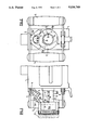
- FIG. 3 shows a longitudinal section through the trigger safety according to line III--III of FIG. 4;
- FIG. 4 shows a cross-section through the trigger safety according to line IV--IV of FIG. 3.
- FIGS. 1 and 2 show the rear end of the weapon and the trigger casing 1, in which a fork-shaped trigger 2 and a tumbler release 3 having an actuating plate 3a are pivotably mounted on a common axle 4. Parts 2 and 3 are located between two handles 5.
- trigger 2 and tumbler release 3 may be independently pivoted downwards from an inactive position as represented in FIGS. 1 and 2.
- a firing selection guiding tube 7 with a hold-down spring 8 riveted to its front end is rotatably mounted on buffer cylinder 6 projecting backwards from trigger casing 1.
- the free end of hold-down spring 8 is located at the bottom, i.e. diametrically opposite trigger 2 and tumbler release 3.
- guiding tube 7 and hold-down spring 8 may be rotated counterclockwise by about 180° from the represented position, whereby hold-down spring S can be brought into the area of tumbler release 3.
- hold-down spring may be swiveled over intermediate portion 3b of the tumbler release, and the latter is thus held in its lowered repetitive firing position. Accordingly, repetitive firing is effected each time the trigger is actuated.
- a safety is provided in order to obviate this danger.
- a safety ring 12 having flat milled surfaces 12a is mounted on guiding tube 7. In the shown position of guiding tube 7, surfaces 12a extend vertically, i.e. about parallel to an axial vertical plane passing near the free end of hold-down spring 8.
- the axial end positions of the safety ring 12 are additionally determined by spring-loaded locking balls 16 which are adapted to drop into front locking bores 17 or rear locking bores 18.
- safety ring 12 is shown in its forward end position in which it blocks the pivot movement of trigger 2 and thus prevents any depression of the latter for firing a single shot or a series of shots. Accordingly, the weapon is locked in this position of safety ring 12.
- the safety ring 12 may be pulled backwards without considerable effort into an end position as illustrated by dotted lines in FIG. 1 and determined by locking balls 16 dropping into locking bores 18, in which position the pivot movement of trigger 2 is no longer blocked. The weapon can thus be operated normally.
- the spring-loaded positioning pin 10 engaging with annular groove 11 of buffer cylinder 6 serves not only the purpose of limiting the rotational movement of about 180° of guide tube 7 and safety ring 12 mounted thereon, but also that of securing those parts on buffer cylinder 6. If the safety ring together with guiding tube 7 is retracted sufficiently forcefully, positioning pin 10 may be disengaged from groove 11 while overcoming the pressure of spring 9, and the safety ring may be drawn from the buffer cylinder together with the guiding tube. Consequently, the corresponding guiding tube 7 of an existing weapon without a safety ring 12 may be simply drawn off from buffer cylinder 6 and replaced with the above-described assembly having a safety ring 12. Existing weapons may thus be retrofitted without any problems.
Landscapes
- Engineering & Computer Science (AREA)
- General Engineering & Computer Science (AREA)
- Toys (AREA)
- Telescopes (AREA)
- Orthopedics, Nursing, And Contraception (AREA)
- Fats And Perfumes (AREA)
- Catching Or Destruction (AREA)
Applications Claiming Priority (2)
| Application Number | Priority Date | Filing Date | Title |
|---|---|---|---|
| EP89810192A EP0386389B1 (de) | 1989-03-10 | 1989-03-10 | Abzugsicherung an einer Schusswaffe |
| EP89810192.8 | 1989-03-10 |
Publications (1)
| Publication Number | Publication Date |
|---|---|
| US5036749A true US5036749A (en) | 1991-08-06 |
Family
ID=8203135
Family Applications (1)
| Application Number | Title | Priority Date | Filing Date |
|---|---|---|---|
| US07/489,225 Expired - Fee Related US5036749A (en) | 1989-03-10 | 1990-03-06 | Trigger safety for a firearm |
Country Status (5)
| Country | Link |
|---|---|
| US (1) | US5036749A (de) |
| EP (1) | EP0386389B1 (de) |
| AT (1) | ATE98013T1 (de) |
| DE (1) | DE58906318D1 (de) |
| ES (1) | ES2047150T3 (de) |
Citations (7)
| Publication number | Priority date | Publication date | Assignee | Title |
|---|---|---|---|---|
| CH14263A (fr) * | 1897-04-17 | 1897-10-31 | Maxim Hiram Stevens | Arme à feu automatique perfectionnée |
| FR347528A (fr) * | 1904-01-23 | 1905-03-13 | Armes De Guerre Fab Nat | Dispositif de sureté pour fusils |
| US1249576A (en) * | 1916-12-29 | 1917-12-11 | Joseph H Wesson | Safety device for shotguns. |
| US1451443A (en) * | 1918-12-04 | 1923-04-10 | Fowler Elbert | Machine gun |
| US1803349A (en) * | 1929-11-15 | 1931-05-05 | Colt S Mfg Co | Automatic firearm |
| US2050539A (en) * | 1932-10-18 | 1936-08-11 | Colt S Mfg Co | Firing mechanism for machine guns |
| US2374378A (en) * | 1943-04-23 | 1945-04-24 | Harrington & Richardson Arms C | Bolt-action firearm |
-
1989
- 1989-03-10 ES ES89810192T patent/ES2047150T3/es not_active Expired - Lifetime
- 1989-03-10 DE DE89810192T patent/DE58906318D1/de not_active Expired - Fee Related
- 1989-03-10 EP EP89810192A patent/EP0386389B1/de not_active Expired - Lifetime
- 1989-03-10 AT AT89810192T patent/ATE98013T1/de not_active IP Right Cessation
-
1990
- 1990-03-06 US US07/489,225 patent/US5036749A/en not_active Expired - Fee Related
Patent Citations (7)
| Publication number | Priority date | Publication date | Assignee | Title |
|---|---|---|---|---|
| CH14263A (fr) * | 1897-04-17 | 1897-10-31 | Maxim Hiram Stevens | Arme à feu automatique perfectionnée |
| FR347528A (fr) * | 1904-01-23 | 1905-03-13 | Armes De Guerre Fab Nat | Dispositif de sureté pour fusils |
| US1249576A (en) * | 1916-12-29 | 1917-12-11 | Joseph H Wesson | Safety device for shotguns. |
| US1451443A (en) * | 1918-12-04 | 1923-04-10 | Fowler Elbert | Machine gun |
| US1803349A (en) * | 1929-11-15 | 1931-05-05 | Colt S Mfg Co | Automatic firearm |
| US2050539A (en) * | 1932-10-18 | 1936-08-11 | Colt S Mfg Co | Firing mechanism for machine guns |
| US2374378A (en) * | 1943-04-23 | 1945-04-24 | Harrington & Richardson Arms C | Bolt-action firearm |
Also Published As
| Publication number | Publication date |
|---|---|
| DE58906318D1 (de) | 1994-01-13 |
| ES2047150T3 (es) | 1994-02-16 |
| EP0386389B1 (de) | 1993-12-01 |
| ATE98013T1 (de) | 1993-12-15 |
| EP0386389A1 (de) | 1990-09-12 |
Similar Documents
| Publication | Publication Date | Title |
|---|---|---|
| US3745881A (en) | Combination slide latch and takedown mechanism for automatic pistol | |
| US3791060A (en) | Convertible bolt action rifle | |
| US5722194A (en) | Weapon bolt | |
| US11320222B2 (en) | Charging handle for firearms | |
| US2780145A (en) | Breech block return means | |
| US4279191A (en) | Firearms | |
| US20030183068A1 (en) | Closed bolt firing delayed blowback automatic handgun firearm | |
| KR102709716B1 (ko) | 자동 장전식 화기용 무기 리시버 및 무기 리시버가 구비된 자동 장전식 화기 | |
| US2645873A (en) | Slide-actuated firearm with tilting locking block | |
| US4305218A (en) | Safety mechanism for a firearm | |
| US8656620B2 (en) | Breech for a repeating firearm | |
| US5458046A (en) | Breech mechanism for a firearm, especially a repeater weapon | |
| US2688203A (en) | Folding light automatic rifle | |
| US2548622A (en) | Firing mechanism for submachine guns | |
| US2719375A (en) | Firearm with a pair of action bars | |
| US2832266A (en) | Automatic pistol | |
| US1446763A (en) | Firearm | |
| US5036749A (en) | Trigger safety for a firearm | |
| US2416287A (en) | Grenade launcher | |
| US3601918A (en) | Firing pin safety mechanism | |
| US3797154A (en) | Sear-disconnector for lever-action firearms | |
| US4054003A (en) | Firearm safety device | |
| US6481135B2 (en) | Rotatable breech mechanism | |
| US2139648A (en) | Gun | |
| US2107359A (en) | Barrel-holding device for automatic pistols |
Legal Events
| Date | Code | Title | Description |
|---|---|---|---|
| AS | Assignment |
Owner name: SCHWEIZERISCHE EIDGENOSSENSCHAFT, EIDGENOSSISCHE W Free format text: ASSIGNMENT OF ASSIGNORS INTEREST.;ASSIGNOR:SCHAFFNER, KURT;REEL/FRAME:005246/0874 Effective date: 19900226 |
|
| CC | Certificate of correction | ||
| FPAY | Fee payment |
Year of fee payment: 4 |
|
| REMI | Maintenance fee reminder mailed | ||
| LAPS | Lapse for failure to pay maintenance fees | ||
| FP | Lapsed due to failure to pay maintenance fee |
Effective date: 19990806 |
|
| STCH | Information on status: patent discontinuation |
Free format text: PATENT EXPIRED DUE TO NONPAYMENT OF MAINTENANCE FEES UNDER 37 CFR 1.362 |