US5035626A - Markerboard - Google Patents
Markerboard Download PDFInfo
- Publication number
- US5035626A US5035626A US07/531,994 US53199490A US5035626A US 5035626 A US5035626 A US 5035626A US 53199490 A US53199490 A US 53199490A US 5035626 A US5035626 A US 5035626A
- Authority
- US
- United States
- Prior art keywords
- substrate
- markerboard
- erasable
- edge
- plastic sheet
- Prior art date
- Legal status (The legal status is an assumption and is not a legal conclusion. Google has not performed a legal analysis and makes no representation as to the accuracy of the status listed.)
- Expired - Fee Related
Links
- 239000000758 substrate Substances 0.000 claims abstract description 40
- 239000002985 plastic film Substances 0.000 claims abstract description 23
- 239000004743 Polypropylene Substances 0.000 claims description 6
- -1 polypropylene Polymers 0.000 claims description 6
- 229920001155 polypropylene Polymers 0.000 claims description 6
- 125000000391 vinyl group Chemical group [H]C([*])=C([H])[H] 0.000 claims description 5
- 229920002554 vinyl polymer Polymers 0.000 claims description 5
- 239000011248 coating agent Substances 0.000 claims description 3
- 238000000576 coating method Methods 0.000 claims description 3
- 239000003550 marker Substances 0.000 description 5
- 238000005192 partition Methods 0.000 description 5
- 239000000853 adhesive Substances 0.000 description 4
- 230000001070 adhesive effect Effects 0.000 description 4
- 238000009432 framing Methods 0.000 description 4
- 229920002457 flexible plastic Polymers 0.000 description 3
- 239000006260 foam Substances 0.000 description 3
- 238000004519 manufacturing process Methods 0.000 description 3
- 238000009966 trimming Methods 0.000 description 3
- 229920000877 Melamine resin Polymers 0.000 description 2
- 229910000831 Steel Inorganic materials 0.000 description 2
- 229910052782 aluminium Inorganic materials 0.000 description 2
- XAGFODPZIPBFFR-UHFFFAOYSA-N aluminium Chemical compound [Al] XAGFODPZIPBFFR-UHFFFAOYSA-N 0.000 description 2
- 239000000463 material Substances 0.000 description 2
- JDSHMPZPIAZGSV-UHFFFAOYSA-N melamine Chemical compound NC1=NC(N)=NC(N)=N1 JDSHMPZPIAZGSV-UHFFFAOYSA-N 0.000 description 2
- 239000002245 particle Substances 0.000 description 2
- 229910052573 porcelain Inorganic materials 0.000 description 2
- 239000010959 steel Substances 0.000 description 2
- 238000010276 construction Methods 0.000 description 1
- 238000001125 extrusion Methods 0.000 description 1
- 229910052751 metal Inorganic materials 0.000 description 1
- 239000002184 metal Substances 0.000 description 1
- 238000000034 method Methods 0.000 description 1
- 239000000203 mixture Substances 0.000 description 1
- 229920000098 polyolefin Polymers 0.000 description 1
- 239000007787 solid Substances 0.000 description 1
- 239000002023 wood Substances 0.000 description 1
Images


Classifications
-
- G—PHYSICS
- G09—EDUCATION; CRYPTOGRAPHY; DISPLAY; ADVERTISING; SEALS
- G09B—EDUCATIONAL OR DEMONSTRATION APPLIANCES; APPLIANCES FOR TEACHING, OR COMMUNICATING WITH, THE BLIND, DEAF OR MUTE; MODELS; PLANETARIA; GLOBES; MAPS; DIAGRAMS
- G09B29/00—Maps; Plans; Charts; Diagrams, e.g. route diagram
- G09B29/001—Planning boards
-
- E—FIXED CONSTRUCTIONS
- E04—BUILDING
- E04B—GENERAL BUILDING CONSTRUCTIONS; WALLS, e.g. PARTITIONS; ROOFS; FLOORS; CEILINGS; INSULATION OR OTHER PROTECTION OF BUILDINGS
- E04B2/00—Walls, e.g. partitions, for buildings; Wall construction with regard to insulation; Connections specially adapted to walls
- E04B2/74—Removable non-load-bearing partitions; Partitions with a free upper edge
- E04B2/7407—Removable non-load-bearing partitions; Partitions with a free upper edge assembled using frames with infill panels or coverings only; made-up of panels and a support structure incorporating posts
- E04B2/7416—Removable non-load-bearing partitions; Partitions with a free upper edge assembled using frames with infill panels or coverings only; made-up of panels and a support structure incorporating posts with free upper edge, e.g. for use as office space dividers
- E04B2/7433—Removable non-load-bearing partitions; Partitions with a free upper edge assembled using frames with infill panels or coverings only; made-up of panels and a support structure incorporating posts with free upper edge, e.g. for use as office space dividers with panels and support posts
-
- G—PHYSICS
- G09—EDUCATION; CRYPTOGRAPHY; DISPLAY; ADVERTISING; SEALS
- G09F—DISPLAYING; ADVERTISING; SIGNS; LABELS OR NAME-PLATES; SEALS
- G09F15/00—Boards, hoardings, pillars, or like structures for notices, placards, posters, or the like
- G09F15/0006—Boards, hoardings, pillars, or like structures for notices, placards, posters, or the like planar structures comprising one or more panels
- G09F15/0012—Boards, hoardings, pillars, or like structures for notices, placards, posters, or the like planar structures comprising one or more panels frames therefor
Definitions
- the invention relates in general to a markerboard, and more specifically to a markerboard suitable for use with an office space dividing partition system.
- Markerboards for use in office space dividing partition systems usually have a fixed outwardly extending ledge which extends across the bottom thereof for supporting dry erase markers and erasers.
- markerboards usually require an outer frame for concealing the edges of the erasable surface, as materials commonly used for marker surfaces, such as porcelain steel and melamine, often chip when cut to size.
- Porcelain steel and melamine boards would be costly to manufacture with finished wrapped around surfaces or edges that would be suitable for flush trim or framing, e.g., trim or framing that does not overlap the edges of the marker surface.
- the present invention is a new and improved markerboard for office space dividing partition systems which has a very thin profile.
- the edges of the markerboard's communicating surface are all finished, permitting flush trimming or framing pieces to be used, and also enabling the upper edge to be untrimmed, if desired.
- the structure of the markerboard which permits easily achieving finished edges of the communicating surface also contributes to a relatively low manufacturing cost.
- the markerboard includes a substrate, such as particle board, having front and back major surfaces and side, top, and bottom edges.
- a flexible plastic sheet having an erasable surface on at least one side thereof, such as vinyl having a coating of polypropylene, is fixed to the front surface of the substrate, such as with an adhesive, and the sheet extends at least partially over the edges.
- the plastic sheet is wrapped completely over the top edge, providing a finished edge without trim.
- the at least partial wrap over the side and bottom edges of the substrate permits side stiles and a bottom rail to be attached to the substrate which are flush with the erasable surface, i.e., there is no overlap of the stiles and rail, permitting vertically oriented front surfaces of the side stiles and bottom rail to be co-planar with the erasable surface.
- the bottom rail is provided with a cavity accessible from the front surface via an elongated groove, the bottom of which is defined by an upstanding lip suitable for hanging accessories, such as a tray for holding dry erase markers and an eraser.
- accessories such as a tray for holding dry erase markers and an eraser.
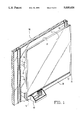
- FIG. 1 is a perspective view of a markerboard constructed according to the teachings of the invention
- FIG. 2 is an exploded perspective view of the markerboard shown in FIG. 1;
- FIG. 3 is a rear elevational view of the markerboard shown in FIG. 1;
- FIG. 4 is an enlarged, fragmentary end elevational view of the markerboard shown in FIG. 1, illustrating the application of a polypropylene coated vinyl sheet to a substrate;
- FIG. 5 is a top plan view of the markerboard shown in FIG. 1;
- FIG. 6 is a sectional view of the markerboard, taken between and in the direction of arrows VI--VI in FIG. 3.
- Markerboard 10 constructed according to the teachings of the invention.
- Markerboard 10 includes a solid substrate or core 12, best shown in FIGS. 2, 3, 4 and 6, erasable means 14 best shown in FIGS. 2, 3, 4 and 6, first and second stiles or vertical frame members 16 and 18, best shown in FIGS. 1 and 2, a lower rail 20, best shown in FIGS. 2 and 6, and a plurality of mounting clips 22, best shown in FIG. 2.
- the substrate 12 is constructed of a suitable support material, such as wood particle board.
- Substrate 12 has a relatively large outer rectangular configuration, such as 28 to 40 inches high and 36 to 48 inches wide, and a relatively thin depth, such as 0.75 inch.
- Substrate 12 has front and back major opposed parallel surfaces 24 and 26, respectively, best shown in FIG. 6, first and second longitudinal ends having vertically extending side edges 28 and 30, respectively, a top edge 32 and a bottom edge 34.
- the edges 28, 30, 32 and 34 extend between, and are in general perpendicular to, the major front and back surfaces 24 and 26.
- the erasable means 14 is a flexible plastic sheet, hereinafter referred to as plastic sheet 14, with plastic sheet 14 being sized to cover the front surface 24 of substrate 12, and additionally to completely wrap over the top edge 32, and to at least partially wrap over the first and second side and bottom edges 28, 30 and 34, respectively.
- plastic sheet 14 is a polypropylene coated vinyl sheet.
- Plastic sheet 14 is fixed to substrate 12, such as with a suitable adhesive.
- a suitable polypropylene coated vinyl, adhesive-backed sheet is available from Sun Process, Elk Grove Village, Ill. 60007.
- FIG. 4 is a side elevational view of substrate 12 with plastic sheet 14 secured thereto, indicating the . complete wrap of the top edge 32 which continues on to the back surface 26 of substrate 12, ending at sheet edge 36.
- Plastic sheet 14 extends partially across each side edge 28 and 30, as illustrated in FIG. 4, ending at sheet edge 38.
- plastic sheet 14 extends partially across the bottom edge 34, ending at sheet edge 40.
- the partial wraps of the side edges 28 and 30 and bottom edge 34 is sufficient, as these edges are covered and the sheet edges captured by the stiles 16 and 18 and bottom rail 20 during assembly of markerboard 10, as will be hereinafter explained.
- the bottom rail 20 is preferably a metallic extrusion, such as aluminum, with the bottom rail 20 being shown in perspective in FIG. 2, and more clearly in an enlarged cross-sectional view in FIG. 6, which view is taken between and in the direction of arrows VI--VI in the rear view of markerboard 10 in FIG. 3.
- Bottom rail 20 is an elongated structure having first and second longitudinal ends 42 and 44, respectively.
- bottom rail 20 includes an upstanding wall 46 at an upper end 47 thereof which is sized to snugly enter a groove 48 in the bottom edge 34 of substrate 12. Upstanding wall 46 rises upwardly from a central portion of a horizontal member 50 having upturned lips 52 and 54 which run along front and rear sides 56 and 58 of rail 20.
- the bottom edge 34 of substrate 12 rests upon lips 52 and 54, with a piece of foam tape 60 being disposed in a cavity formed between the front lip 52 and wall 46.
- the foam tape 60 such as a polyolefin, closed cell foam tape having an adhesive on one side, for example, insures that the portion of plastic sheet 14 which is folded over the bottom edge 34 of substrate 12 remains folded over and in continuous contact with bottom edge 34.
- a wall 62 depends from a central portion of horizontal member 50, which joins a horizontal leg 64 via a right angle bend 66 which directs horizontal leg 64 towards the front side 56 of rail 20.
- Horizontal leg 64 joins a front wall 68 below an upper edge 70 thereof, forming a cavity 72 accessible via an elongated slot 74 which runs along the front side 56 of rail 20.
- the front wall 68 is substantially co-planar with the plastic sheet 14, with a vertical plane 76 passing through the outer facing surfaces of plastic sheet 14 and the front wall 68.
- the front wall 68 enters a bottom edge 78 via a smoothly curved right angle bend 80.
- the bottom edge 78 ends at 82, with the surface of end 82 being co-planar with lip 54 and the back surface 26 of substrate 12, as indicated by plane 83.
- An additional stiffening leg 84 may extend perpendicularly outward from an inner side of front wall 68, towards the back 58 of rail 20, ending at 86, which end also lies in plane 83.
- the front wall 68 forms a lip 88 starting at its upper edge 70 and ending at horizontal portion 64, which lip functions to hold optional accessories, such as a marker and eraser tray 90 shown in FIG. 1 and in phantom in FIG. 6.
- the stiles 16 and 18 are preferably formed of metal, such as aluminum, and they have a length dimension selected to cover and conceal the side edges 28 and 30 of the substrate 12, as well as to cover and conceal the ends 42 and 44 of the bottom rail 20. In addition to the trim function, the stiles 16 and 18 provide a uniform clamping function for the partial over-wrap of the plastic sheet 14 around the side edges 28 and 30 of the substrate 12.
- Each stile 16 and 18, such as stile 16, as best shown in FIG. 2, has a vertically oriented outer side 92 which smoothly curves into upper and lower portions 94 and 96, which portions smoothly blend into the upper edge 32 of the substrate 12 and the lower edge 78 of the bottom rail.
- a vertically oriented front 98 of stile 16 is coplanar with the plastic sheet 14 and the front wall 68 of the bottom rail 20, and a back portion 100 of stile 16 includes an integral outwardly extending flange 101 which lies against the back surface 26 of substrate 12.
- Flange 101 has a plurality of spaced openings 102 for receiving screws 104.
- Each mounting clip 22, as best shown in FIG. 2, is an L-shaped bracket having first and second legs 106 and 108.
- Leg 106 has openings 110 for receiving screws 112 for attaching mounting clip 22 to the back portion 100 of a stile 16 or 18.
- the second leg 108 has T-shaped connectors 114 dimensioned to enter openings in slotted standards 116 of an office space dividing partition system 118 shown in FIG. 1.
- a new markerboard 10 which provides a writing or communicating surface for dry erase markers which includes a flexible plastic sheet 14 wrapped over a front surface of a substrate 12, including the substrate's edges, permitting a wrap-around marker surface on the upper edge 32, and permitting flush trim or frame pieces to be used on the remaining three edges 28, 30 and 34.
- No parts of the markerboard 10 extend past the plane 76 of the marker surface, providing a very thin profile of about 0.75 inch.
- a bottom rail 20 has an elongated slot 74 having an accessory receiving lip 88 for optionally hanging items such as a small shelf 90 for holding a dry erasable pen set and an eraser, paper management items, and the like.
- Markerboard 10 may be quickly attached to the slotted standards 116 of an office space dividing partition system 118, at any desired height, and just as quickly removed, using slotted standard mounting clips 22 which are attached to the back side of markerboard 10.
- the disclosed construction of markerboard 10 facilitates manufacturing thereof, without cutting and chipping problems.
Abstract
Description
Claims (6)
Priority Applications (1)
| Application Number | Priority Date | Filing Date | Title |
|---|---|---|---|
| US07/531,994 US5035626A (en) | 1990-06-01 | 1990-06-01 | Markerboard |
Applications Claiming Priority (1)
| Application Number | Priority Date | Filing Date | Title |
|---|---|---|---|
| US07/531,994 US5035626A (en) | 1990-06-01 | 1990-06-01 | Markerboard |
Publications (1)
| Publication Number | Publication Date |
|---|---|
| US5035626A true US5035626A (en) | 1991-07-30 |
Family
ID=24119966
Family Applications (1)
| Application Number | Title | Priority Date | Filing Date |
|---|---|---|---|
| US07/531,994 Expired - Fee Related US5035626A (en) | 1990-06-01 | 1990-06-01 | Markerboard |
Country Status (1)
| Country | Link |
|---|---|
| US (1) | US5035626A (en) |
Cited By (30)
| Publication number | Priority date | Publication date | Assignee | Title |
|---|---|---|---|---|
| US5131849A (en) * | 1991-10-04 | 1992-07-21 | Perrero John J | Teaching board apparatus |
| US5176522A (en) * | 1992-04-16 | 1993-01-05 | Robertson Jr Charles D | Erasable marker board assembly |
| US5409383A (en) * | 1993-02-23 | 1995-04-25 | Mannino; Thomas C. | Multi-functional writing device |
| US5622504A (en) * | 1995-04-20 | 1997-04-22 | Jamie H. Tarziers | Reusable bulletin board display |
| US5626478A (en) * | 1995-10-27 | 1997-05-06 | Gatlin; Gray | Portable coaching device and method |
| US5725381A (en) * | 1996-10-03 | 1998-03-10 | Kollath; Richard Craig | Motivation system for children |
| US5727952A (en) * | 1996-07-19 | 1998-03-17 | Classic Modular Systems, Inc. | Edge-encapsulated writing board |
| US5752837A (en) * | 1996-07-26 | 1998-05-19 | Palmer; Mary Margaret | Tool kit for facilitators and trainers |
| GB2334002A (en) * | 1998-01-14 | 1999-08-11 | Steelcase Inc | Office wall partition with attached markerboard |
| GB2334976A (en) * | 1998-03-06 | 1999-09-08 | Komfort Systems Ltd | Partition assembly connector |
| US6139331A (en) * | 1999-12-21 | 2000-10-31 | Owen; Mike C. | Board base apparatus |
| US20030201376A1 (en) * | 2002-04-29 | 2003-10-30 | Colin Knight | Devices and method for hanging a display board |
| US20040229202A1 (en) * | 2003-05-15 | 2004-11-18 | Sohl Henry Ellis | Dry erase board with image in relief |
| WO2005002391A2 (en) * | 2003-06-24 | 2005-01-13 | Best Rite Manufacturing | Encapsulated tray, end caps, and method for making the same for a writing board |
| US20050127255A1 (en) * | 2003-06-24 | 2005-06-16 | Greg Moore | Encapsulated end caps and method of making the same for a writing board tray |
| WO2005070702A1 (en) * | 2004-01-16 | 2005-08-04 | Michael Owen | White board and white board display system |
| US20060003307A1 (en) * | 2004-07-02 | 2006-01-05 | 3M Innovative Properties Company | Dry erase article |
| US20080248456A1 (en) * | 2007-04-09 | 2008-10-09 | Cheris Albert B | Reorientable Dry Erase Board |
| US20080286744A1 (en) * | 2007-04-06 | 2008-11-20 | Cheris Albert B | Foldable Dry Erase Board |
| US20090029338A1 (en) * | 2007-07-24 | 2009-01-29 | Acco Brands Usa Llc | Display board assembly |
| GB2437762B (en) * | 2006-05-06 | 2010-09-29 | Tecna Display Ltd | Display hanger |
| USD669531S1 (en) | 2012-02-24 | 2012-10-23 | Steelcase Inc. | Display board |
| USD669534S1 (en) * | 2011-11-08 | 2012-10-23 | Panasonic Corporation | Electronic whiteboard |
| US20130078025A1 (en) * | 2010-03-31 | 2013-03-28 | Carmit Turgeman | Refill system and method |
| US9066589B2 (en) | 2012-02-27 | 2015-06-30 | Steelcase Inc. | Learning suite furniture system |
| USD787593S1 (en) | 2016-06-29 | 2017-05-23 | Bruce Robins | Whiteboard |
| JP2019035206A (en) * | 2017-08-10 | 2019-03-07 | 明正工業株式会社 | Underground double wall structure |
| JP2019035207A (en) * | 2017-08-10 | 2019-03-07 | 明正工業株式会社 | Underground double wall structure |
| US10306981B2 (en) | 2016-12-02 | 2019-06-04 | Altria Client Services Llc | Universal mounting system (UMS) and method of installing thereof |
| US10334970B2 (en) * | 2016-12-02 | 2019-07-02 | Altria Client Services Llc | Adaptive merchandising platform (AMP) mounting system and method of installing thereof |
Citations (10)
| Publication number | Priority date | Publication date | Assignee | Title |
|---|---|---|---|---|
| US883402A (en) * | 1907-05-27 | 1908-03-31 | John W Hainline | Tray attachment for blackboards. |
| US1984845A (en) * | 1932-04-25 | 1934-12-18 | Howard L Smith | Attachment for blackboards |
| US3283421A (en) * | 1964-10-30 | 1966-11-08 | Andrew F Schott | Educational worksheet |
| DE2114620A1 (en) * | 1971-03-26 | 1973-04-05 | Rexham Corp | UNIVERSALLY USABLE GRAPHIC DISPLAY AND REPRESENTATION MATERIAL |
| US3762116A (en) * | 1971-07-02 | 1973-10-02 | Westinghouse Electric Corp | Space divider system and connector assembly therefor |
| US3949132A (en) * | 1972-05-25 | 1976-04-06 | The Gillette Company | Marking boards and erasable ink compositions therefor |
| GB1450281A (en) * | 1974-01-03 | 1976-09-22 | Stratabord Ltd | Dry-wipe writing system |
| US4401222A (en) * | 1981-06-08 | 1983-08-30 | Westinghouse Electric Corp. | Support rail |
| US4779369A (en) * | 1984-01-16 | 1988-10-25 | Universal Components Limited | Display apparatus |
| US4978568A (en) * | 1988-08-08 | 1990-12-18 | Hach Associates, Inc. | Flexible writing surface |
-
1990
- 1990-06-01 US US07/531,994 patent/US5035626A/en not_active Expired - Fee Related
Patent Citations (10)
| Publication number | Priority date | Publication date | Assignee | Title |
|---|---|---|---|---|
| US883402A (en) * | 1907-05-27 | 1908-03-31 | John W Hainline | Tray attachment for blackboards. |
| US1984845A (en) * | 1932-04-25 | 1934-12-18 | Howard L Smith | Attachment for blackboards |
| US3283421A (en) * | 1964-10-30 | 1966-11-08 | Andrew F Schott | Educational worksheet |
| DE2114620A1 (en) * | 1971-03-26 | 1973-04-05 | Rexham Corp | UNIVERSALLY USABLE GRAPHIC DISPLAY AND REPRESENTATION MATERIAL |
| US3762116A (en) * | 1971-07-02 | 1973-10-02 | Westinghouse Electric Corp | Space divider system and connector assembly therefor |
| US3949132A (en) * | 1972-05-25 | 1976-04-06 | The Gillette Company | Marking boards and erasable ink compositions therefor |
| GB1450281A (en) * | 1974-01-03 | 1976-09-22 | Stratabord Ltd | Dry-wipe writing system |
| US4401222A (en) * | 1981-06-08 | 1983-08-30 | Westinghouse Electric Corp. | Support rail |
| US4779369A (en) * | 1984-01-16 | 1988-10-25 | Universal Components Limited | Display apparatus |
| US4978568A (en) * | 1988-08-08 | 1990-12-18 | Hach Associates, Inc. | Flexible writing surface |
Cited By (56)
| Publication number | Priority date | Publication date | Assignee | Title |
|---|---|---|---|---|
| US5131849A (en) * | 1991-10-04 | 1992-07-21 | Perrero John J | Teaching board apparatus |
| US5176522A (en) * | 1992-04-16 | 1993-01-05 | Robertson Jr Charles D | Erasable marker board assembly |
| US5409383A (en) * | 1993-02-23 | 1995-04-25 | Mannino; Thomas C. | Multi-functional writing device |
| US5622504A (en) * | 1995-04-20 | 1997-04-22 | Jamie H. Tarziers | Reusable bulletin board display |
| US5626478A (en) * | 1995-10-27 | 1997-05-06 | Gatlin; Gray | Portable coaching device and method |
| US5727952A (en) * | 1996-07-19 | 1998-03-17 | Classic Modular Systems, Inc. | Edge-encapsulated writing board |
| US5752837A (en) * | 1996-07-26 | 1998-05-19 | Palmer; Mary Margaret | Tool kit for facilitators and trainers |
| US5725381A (en) * | 1996-10-03 | 1998-03-10 | Kollath; Richard Craig | Motivation system for children |
| GB2334002A (en) * | 1998-01-14 | 1999-08-11 | Steelcase Inc | Office wall partition with attached markerboard |
| GB2334002B (en) * | 1998-01-14 | 2001-11-21 | Steelcase Inc | Partition system with attached markerboard |
| GB2334976A (en) * | 1998-03-06 | 1999-09-08 | Komfort Systems Ltd | Partition assembly connector |
| GB2334976B (en) * | 1998-03-06 | 2002-08-14 | Komfort Systems Ltd | Panel assembly apparatus |
| US6139331A (en) * | 1999-12-21 | 2000-10-31 | Owen; Mike C. | Board base apparatus |
| US7147196B2 (en) | 2002-04-29 | 2006-12-12 | General Binding Corporation | Devices and method for hanging a display board |
| US20030201376A1 (en) * | 2002-04-29 | 2003-10-30 | Colin Knight | Devices and method for hanging a display board |
| US20040229202A1 (en) * | 2003-05-15 | 2004-11-18 | Sohl Henry Ellis | Dry erase board with image in relief |
| US6945785B2 (en) * | 2003-05-15 | 2005-09-20 | Henry Ellis Sohl | Dry erase board with image in relief |
| WO2005002391A2 (en) * | 2003-06-24 | 2005-01-13 | Best Rite Manufacturing | Encapsulated tray, end caps, and method for making the same for a writing board |
| US20050127255A1 (en) * | 2003-06-24 | 2005-06-16 | Greg Moore | Encapsulated end caps and method of making the same for a writing board tray |
| US7249745B2 (en) | 2003-06-24 | 2007-07-31 | Mooreco, L.P. | Encapsulated end caps and method of making the same for a writing board tray |
| US20050014125A1 (en) * | 2003-06-24 | 2005-01-20 | Greg Moore | Encapsulated tray, end caps, and method for making the same for a writing board |
| WO2005002391A3 (en) * | 2003-06-24 | 2005-10-27 | Best Rite Mfg | Encapsulated tray, end caps, and method for making the same for a writing board |
| US7207805B2 (en) | 2003-06-24 | 2007-04-24 | Mooreco, L.P. | Encapsulated tray and end caps for a writing board |
| US20050191611A1 (en) * | 2004-01-16 | 2005-09-01 | Michael Owen | White board and white board display system |
| WO2005070702A1 (en) * | 2004-01-16 | 2005-08-04 | Michael Owen | White board and white board display system |
| US7604481B2 (en) * | 2004-01-16 | 2009-10-20 | Meadwestvaco Corporation | White board and white board display system |
| US20060003307A1 (en) * | 2004-07-02 | 2006-01-05 | 3M Innovative Properties Company | Dry erase article |
| US7399184B2 (en) * | 2004-07-02 | 2008-07-15 | 3M Innovative Properties Company | Dry erase article |
| WO2006083256A1 (en) * | 2005-02-02 | 2006-08-10 | Best-Rite Manufacturing | Encapsulated end caps and method of making the same for a writing board tray |
| GB2437762B (en) * | 2006-05-06 | 2010-09-29 | Tecna Display Ltd | Display hanger |
| US20080286744A1 (en) * | 2007-04-06 | 2008-11-20 | Cheris Albert B | Foldable Dry Erase Board |
| US7980857B2 (en) | 2007-04-06 | 2011-07-19 | Tenex Corporation | Foldable dry erase board |
| US20080248456A1 (en) * | 2007-04-09 | 2008-10-09 | Cheris Albert B | Reorientable Dry Erase Board |
| US20090029338A1 (en) * | 2007-07-24 | 2009-01-29 | Acco Brands Usa Llc | Display board assembly |
| US20130078025A1 (en) * | 2010-03-31 | 2013-03-28 | Carmit Turgeman | Refill system and method |
| USD669534S1 (en) * | 2011-11-08 | 2012-10-23 | Panasonic Corporation | Electronic whiteboard |
| USD669531S1 (en) | 2012-02-24 | 2012-10-23 | Steelcase Inc. | Display board |
| US10292490B2 (en) | 2012-02-27 | 2019-05-21 | Steelcase Inc. | Table and lectern furniture system |
| US10448734B2 (en) | 2012-02-27 | 2019-10-22 | Steelcase Inc. | Table and lectern furniture system |
| US9723921B2 (en) | 2012-02-27 | 2017-08-08 | Steelcase Inc. | Table and lectern furniture system |
| US11759008B2 (en) | 2012-02-27 | 2023-09-19 | Steelcase Inc. | Table and panel furniture system |
| US11369195B2 (en) | 2012-02-27 | 2022-06-28 | Steelcase Inc. | Table and panel furniture system |
| US9066589B2 (en) | 2012-02-27 | 2015-06-30 | Steelcase Inc. | Learning suite furniture system |
| US9226578B2 (en) | 2012-02-27 | 2016-01-05 | Steelcase Inc. | Learning suite furniture system |
| US11116312B2 (en) | 2012-02-27 | 2021-09-14 | Steelcase Inc. | Table and panel furniture system |
| USD787593S1 (en) | 2016-06-29 | 2017-05-23 | Bruce Robins | Whiteboard |
| US11160395B2 (en) | 2016-12-02 | 2021-11-02 | Altria Client Services Llc | Method of making support bracket |
| US10548417B2 (en) | 2016-12-02 | 2020-02-04 | Altria Client Services Llc | Adaptive merchandising platform (AMP) mounting system and method of installing thereof |
| US10888179B2 (en) | 2016-12-02 | 2021-01-12 | Altria Client Services Llc | Support bracket for mounting system |
| US10334970B2 (en) * | 2016-12-02 | 2019-07-02 | Altria Client Services Llc | Adaptive merchandising platform (AMP) mounting system and method of installing thereof |
| US10306981B2 (en) | 2016-12-02 | 2019-06-04 | Altria Client Services Llc | Universal mounting system (UMS) and method of installing thereof |
| US11178964B2 (en) | 2016-12-02 | 2021-11-23 | Altria Client Services Llc | Mounting system with horizontally-slideable bracket and support bracket |
| US11707144B2 (en) | 2016-12-02 | 2023-07-25 | Altria Client Services Llc | Method of installing mounting system with support bracket |
| US11864649B2 (en) | 2016-12-02 | 2024-01-09 | Altria Client Services Llc | Method of installing mounting system with insertable brackets and support brackets |
| JP2019035207A (en) * | 2017-08-10 | 2019-03-07 | 明正工業株式会社 | Underground double wall structure |
| JP2019035206A (en) * | 2017-08-10 | 2019-03-07 | 明正工業株式会社 | Underground double wall structure |
Similar Documents
| Publication | Publication Date | Title |
|---|---|---|
| US5035626A (en) | Markerboard | |
| US4197686A (en) | Fabric wall covering system | |
| US5301477A (en) | Panel system | |
| US3294353A (en) | Trim means or a border edge covering | |
| US5906079A (en) | Partition system with attached markerboard | |
| US20170020286A1 (en) | Shelf Cover System Configured To Releasably Attach To Wire Frame Shelves | |
| US20020009703A1 (en) | Two sided writing board | |
| JPS6038123B2 (en) | Furnishing system | |
| US5520234A (en) | Window top decorating assembly | |
| US7225852B2 (en) | Covered pad for wall panel and manufacturing process | |
| US20050236347A1 (en) | Display system | |
| US3857136A (en) | Cable bushing apparatus | |
| US4273277A (en) | Visor-connected tape cartridge holder | |
| JPH0552203B2 (en) | ||
| JP4140966B2 (en) | Wall structure for installation such as shelf holder | |
| US2887739A (en) | Detachable baseboards | |
| US5826848A (en) | Cover for bracket | |
| US3501883A (en) | Method and apparatus for mounting wallboard | |
| GB2236243A (en) | Shelf support means | |
| US3135532A (en) | Easel-back binder | |
| JPS635574Y2 (en) | ||
| US20080098680A1 (en) | Three-dimensional cover tile | |
| CN213778300U (en) | Shelf assembly and refrigerator | |
| US5221067A (en) | Wall partition bracket assembly | |
| JPH052335Y2 (en) |
Legal Events
| Date | Code | Title | Description |
|---|---|---|---|
| AS | Assignment |
Owner name: WESTINGHOUSE ELECTRIC CORPORATION, PENNSYLVANIA Free format text: ASSIGNMENT OF ASSIGNORS INTEREST.;ASSIGNOR:PERSING, BRAIN J.;REEL/FRAME:005399/0638 Effective date: 19900608 |
|
| FEPP | Fee payment procedure |
Free format text: PAYOR NUMBER ASSIGNED (ORIGINAL EVENT CODE: ASPN); ENTITY STATUS OF PATENT OWNER: LARGE ENTITY |
|
| FPAY | Fee payment |
Year of fee payment: 4 |
|
| AS | Assignment |
Owner name: NATIONSBANK, N.A., AS COLLATERAL AGENT, NORTH CARO Free format text: SECURITY AGREEMENT;ASSIGNOR:KNOLL, INC.;REEL/FRAME:007803/0214 Effective date: 19960228 |
|
| AS | Assignment |
Owner name: KNOLL, INC., PENNSYLVANIA Free format text: ASSIGNMENT OF ASSIGNORS INTEREST;ASSIGNOR:WESTINGHOUSE ELECTRIC CORPORATION;REEL/FRAME:007888/0022 Effective date: 19960229 |
|
| AS | Assignment |
Owner name: KNOLL, INC., PENNSYLVANIA Free format text: RELEASE BY SECURED PARTY;ASSIGNOR:NATIONSBANK, N.A. AS COLLATERAL AGENT;REEL/FRAME:008660/0504 Effective date: 19970806 |
|
| REMI | Maintenance fee reminder mailed | ||
| LAPS | Lapse for failure to pay maintenance fees | ||
| FP | Lapsed due to failure to pay maintenance fee |
Effective date: 19990730 |
|
| STCH | Information on status: patent discontinuation |
Free format text: PATENT EXPIRED DUE TO NONPAYMENT OF MAINTENANCE FEES UNDER 37 CFR 1.362 |