US5031302A - Method of making a filler pipe for a fuel tank of a motor vehicle - Google Patents
Method of making a filler pipe for a fuel tank of a motor vehicle Download PDFInfo
- Publication number
- US5031302A US5031302A US07/462,782 US46278290A US5031302A US 5031302 A US5031302 A US 5031302A US 46278290 A US46278290 A US 46278290A US 5031302 A US5031302 A US 5031302A
- Authority
- US
- United States
- Prior art keywords
- sealing ring
- insert
- filler pipe
- ring means
- cross
- Prior art date
- Legal status (The legal status is an assumption and is not a legal conclusion. Google has not performed a legal analysis and makes no representation as to the accuracy of the status listed.)
- Expired - Fee Related
Links
Images

Classifications
-
- B—PERFORMING OPERATIONS; TRANSPORTING
- B60—VEHICLES IN GENERAL
- B60K—ARRANGEMENT OR MOUNTING OF PROPULSION UNITS OR OF TRANSMISSIONS IN VEHICLES; ARRANGEMENT OR MOUNTING OF PLURAL DIVERSE PRIME-MOVERS IN VEHICLES; AUXILIARY DRIVES FOR VEHICLES; INSTRUMENTATION OR DASHBOARDS FOR VEHICLES; ARRANGEMENTS IN CONNECTION WITH COOLING, AIR INTAKE, GAS EXHAUST OR FUEL SUPPLY OF PROPULSION UNITS IN VEHICLES
- B60K15/00—Arrangement in connection with fuel supply of combustion engines or other fuel consuming energy converters, e.g. fuel cells; Mounting or construction of fuel tanks
- B60K15/03—Fuel tanks
- B60K15/04—Tank inlets
-
- Y—GENERAL TAGGING OF NEW TECHNOLOGICAL DEVELOPMENTS; GENERAL TAGGING OF CROSS-SECTIONAL TECHNOLOGIES SPANNING OVER SEVERAL SECTIONS OF THE IPC; TECHNICAL SUBJECTS COVERED BY FORMER USPC CROSS-REFERENCE ART COLLECTIONS [XRACs] AND DIGESTS
- Y10—TECHNICAL SUBJECTS COVERED BY FORMER USPC
- Y10S—TECHNICAL SUBJECTS COVERED BY FORMER USPC CROSS-REFERENCE ART COLLECTIONS [XRACs] AND DIGESTS
- Y10S277/00—Seal for a joint or juncture
- Y10S277/91—O-ring seal
-
- Y—GENERAL TAGGING OF NEW TECHNOLOGICAL DEVELOPMENTS; GENERAL TAGGING OF CROSS-SECTIONAL TECHNOLOGIES SPANNING OVER SEVERAL SECTIONS OF THE IPC; TECHNICAL SUBJECTS COVERED BY FORMER USPC CROSS-REFERENCE ART COLLECTIONS [XRACs] AND DIGESTS
- Y10—TECHNICAL SUBJECTS COVERED BY FORMER USPC
- Y10S—TECHNICAL SUBJECTS COVERED BY FORMER USPC CROSS-REFERENCE ART COLLECTIONS [XRACs] AND DIGESTS
- Y10S277/00—Seal for a joint or juncture
- Y10S277/924—Deformation, material removal, or molding for manufacture of seal
-
- Y—GENERAL TAGGING OF NEW TECHNOLOGICAL DEVELOPMENTS; GENERAL TAGGING OF CROSS-SECTIONAL TECHNOLOGIES SPANNING OVER SEVERAL SECTIONS OF THE IPC; TECHNICAL SUBJECTS COVERED BY FORMER USPC CROSS-REFERENCE ART COLLECTIONS [XRACs] AND DIGESTS
- Y10—TECHNICAL SUBJECTS COVERED BY FORMER USPC
- Y10T—TECHNICAL SUBJECTS COVERED BY FORMER US CLASSIFICATION
- Y10T29/00—Metal working
- Y10T29/49—Method of mechanical manufacture
- Y10T29/49428—Gas and water specific plumbing component making
-
- Y—GENERAL TAGGING OF NEW TECHNOLOGICAL DEVELOPMENTS; GENERAL TAGGING OF CROSS-SECTIONAL TECHNOLOGIES SPANNING OVER SEVERAL SECTIONS OF THE IPC; TECHNICAL SUBJECTS COVERED BY FORMER USPC CROSS-REFERENCE ART COLLECTIONS [XRACs] AND DIGESTS
- Y10—TECHNICAL SUBJECTS COVERED BY FORMER USPC
- Y10T—TECHNICAL SUBJECTS COVERED BY FORMER US CLASSIFICATION
- Y10T29/00—Metal working
- Y10T29/49—Method of mechanical manufacture
- Y10T29/49826—Assembling or joining
- Y10T29/49908—Joining by deforming
- Y10T29/49925—Inward deformation of aperture or hollow body wall
- Y10T29/49927—Hollow body is axially joined cup or tube
-
- Y—GENERAL TAGGING OF NEW TECHNOLOGICAL DEVELOPMENTS; GENERAL TAGGING OF CROSS-SECTIONAL TECHNOLOGIES SPANNING OVER SEVERAL SECTIONS OF THE IPC; TECHNICAL SUBJECTS COVERED BY FORMER USPC CROSS-REFERENCE ART COLLECTIONS [XRACs] AND DIGESTS
- Y10—TECHNICAL SUBJECTS COVERED BY FORMER USPC
- Y10T—TECHNICAL SUBJECTS COVERED BY FORMER US CLASSIFICATION
- Y10T29/00—Metal working
- Y10T29/49—Method of mechanical manufacture
- Y10T29/49826—Assembling or joining
- Y10T29/49908—Joining by deforming
- Y10T29/49938—Radially expanding part in cavity, aperture, or hollow body
- Y10T29/4994—Radially expanding internal tube
Definitions
- the present invention relates to a filler pipe for a fuel tank of a motor vehicle which is provided at its cap end with a cylindrical insert whereby an elastic sealing ring is arranged between an outer surface of the insert and an inner surface of the filler pipe made of plastic material.
- FIG. 4 is a view, partly in cross section, and on an enlarged scale, of the sealing ring according to FIG. 3.
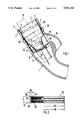
- FIG. 3 illustrates a second embodiment of a filler pipe 28 whereby radial beads 31 are locally provided at an insert 29 within the area of a sealing ring 30 which effect an additional fixing of the sealing ring 30.
- the beads 31 are constructed spherically shaped.
- the sealing ring 30 cooperating with the beads 31 is composed--as viewed in cross section--of two end-face circularly shaped sections 32 and 33 which are connected with each other by a thin-walled web 34.
- the web 34 extends in an auxiliary plane 35 which connects with each other the center points 36 and 37 of the circularly shaped sections 32 and 33 that are disposed one above the other.
Landscapes
- Engineering & Computer Science (AREA)
- Life Sciences & Earth Sciences (AREA)
- Sustainable Development (AREA)
- Sustainable Energy (AREA)
- Chemical & Material Sciences (AREA)
- Combustion & Propulsion (AREA)
- Transportation (AREA)
- Mechanical Engineering (AREA)
- Cooling, Air Intake And Gas Exhaust, And Fuel Tank Arrangements In Propulsion Units (AREA)
Abstract
A filler pipe for a fuel tank of a motor vehicle includes at its cap end a cylindrical insert whereby an elastic sealing ring is arranged between an outer surface of the insert and an inner surface of the filler pipe made of plastic material. In order that a simple cost-favorable connection between the insert and the filler pipe is achieved combined with a good seal, the profiled sealing ring having an elongated cross-sectional shape is mounted on the insert under prestress. Furthermore, the insert and sealing ring are subjected to a common blow-molding operation.
Description
This is a divisional of application Ser. No. 260,730, filed Oct. 14, 1988, now U.S. Pat. No. 4,915,249.
The present invention relates to a filler pipe for a fuel tank of a motor vehicle which is provided at its cap end with a cylindrical insert whereby an elastic sealing ring is arranged between an outer surface of the insert and an inner surface of the filler pipe made of plastic material.
With a known arrangement of the aforementioned type (EP-A 0 210 322) an insert made of metal is inserted into a preassembled hollow cylindrical extension of the filler pipe made of plastic material, whereby for axially fixing of the insert a flange connection is realized subsequently between the insert and the filler pipe. Furthermore, an elastic sealing ring is clamped-in between an outer surface of the insert and an inner surface of the filler pipe, which is formed by an O-ring.
This arrangement entails the disadvantage that for purposes of the connection of the filler pipe and insert, several time-consuming and cost-intensive operating steps are necessary, as a result of which the manufacturing costs are increased. Additionally, an annular groove has to provided at the insert for the axial fixation of the O-ring because the O-ring would otherwise displace in the axial direction.
It is the object of the present invention to provide a simple cost-favorable connection between the insert and filler pipe. Therebeyond, a functionally correct sealing between insert and filler pipe is to be assured.
The underlying problems are solved according to the present invention in that the sealing ring has a profiled elongated cross-sectional shape and is mounted on the insert under prestress and in that the sealing ring and the insert are fixed by the externally disposed filler pipe.
The principal advantages achieved with the present invention reside in that an automatic fastening for the sealing ring in the axial direction is achieved by the profiled elongated sealing ring mounted under prestress on the insert. A simple cost-favorable connection between the insert and the filler pipe is achieved by the common blow-molding of the insert and of the sealing ring. The grooves provided at the inner surface of the sealing ring assure that the sealing ring cannot displace itself along the outer surface of the insert. The cross-sectional enlargements provided at the outer surface of the sealing ring effect a good form-locking connection between the sealing ring and the filler pipe. If fuel should reach the sealing ring, then the sealing ring made of rubber or plastic material will swell, and the seal between the insert and filler pipe is additionally improved. It is achieved by the flat elongated shape of the sealing ring that it is also reliably retained in position during the relatively high pressures which occur during the blow-molding operation. An additional securing of the sealing ring in the axial direction is achieved in that radial beads are locally provided at the insert, on which the sealing ring is mounted.
These and other objects, features and advantages of the present invention will become more apparent from the following description when taken in connection with the accompanying drawing which shows, for purposes of illustration only, two embodiments in accordance with the present invention, and wherein:
FIG. 1 is a longitudinal cross-sectional view through a filler pipe of a fuel tank in accordance with the present invention;
FIG. 2 is a view, partly in cross section, and on an enlarged scale, of the sealing ring according to FIG. 1;
FIG. 3 is a longitudinal cross-sectional view corresponding to FIG. 1, of a further embodiment of a filler pipe in accordance with the present invention; and
FIG. 4 is a view, partly in cross section, and on an enlarged scale, of the sealing ring according to FIG. 3.
Referring now to the drawing wherein like reference numerals are used throughout the various views to designate like parts, FIG. 1 illustrates a partial area of a filler pipe generally designated by reference numeral 1 and made of plastic material whose one end is connected with a fuel tank (not shown) of a motor vehicle. The other end 2 of the filler pipe 1, which is located remote from the fuel tank, is provided with a cylindrically constructed insert 3 which receives a closure cap (not shown). The insert 3 preferably made of metal has internally a thread 4 which cooperates with an external thread of the closure cap.
According to FIG. 1, the insert 3 is provided at its upper open end 5 with an outwardly directed flange 6 which is supported sectionwise at an end face 7 of the filler pipe 1. A bottom section 8 of the insert 3 which is located in the lower area, closes the pipe section 11 of the filler pipe 1 leading to the fuel tank with the exception of a through-opening 9 for a filling nozzle 10 indicated in dash and dot lines, whereby the through-opening 9 is provided with a pivotal spring-loaded flap 12.
The insert 3 made of several parts includes above the through-opening 9 an annular space 13 which is in communication with a vent line 14 of the filler pipe 1. The vent line 14 is connected laterally at the filler pipe 1 and to an opening 15 of the annular space 13. Several apertures 17 are provided at an inner conical wall 16 forming the annular space 13, through which the air can flow in the direction to the closure cap.
An elastic sealing ring 21 is arranged above the annular space 13 between an outer surface 18 of the insert 3 and an inner surface 19 of a hollow cylindrical section 20 in the upper end area of the filler pipe 1. According to FIGS. 1 and 2, the profiled sealing ring 21 having an elongated cross-sectional shape is mounted under prestress on the outer surface 18 of the insert 3 at any desired place. The insert 3 together with the sealing ring 21 is connected form-lockingly by blow-molding with the externally disposed hollow cylindrical section 20 of the filler pipe 1. This takes place in such a manner that the insert 3 together with the emplaced sealing ring 21 is placed into a blow mold and is subsequently subjected to a blow-molding operation so that the filler pipe 1 surrounds sectionwise the insert 3 and the sealing ring 21. The radial pressure of the sealing ring 21 is attained by the blow-molding.
The sealing ring 21 made of suitable material such as rubber or plastic material includes at its inner surface several grooves 23 placed alongside one another. The radially extending groove 23 are--as viewed in cross section--constructed saw-tooth-like. According to FIG. 2, the grooves 23 are arranged over the entire length L of the sealing ring 21. An axial displacement of the sealing ring 21 during the blow-molding is prevented by the grooves 23 having a slight height and by the flat elongated shape of the sealing ring 21. At its outer surface, the sealing ring 21 is provided locally with cross-sectional enlargements 25. According to FIG. 2, three semi-circularly shaped cross-sectional enlargements 25 arranged at a distance to one another are provided. The cross-sectional enlargements 25 are formed by the semi-circularly shaped beads 26. However, the possibility also exists that the beads be constructed wave-shaped, triangularly shaped, rectangularly shaped or the like. One cylindrical connecting area 27 each is provided between two adjacent beads 26 whereby the connecting area 27 has an outer diameter D2 which is smaller than the outer diameter D1 of the beads 26. The ratio of the length L to the maximum thickness D of the sealing ring 21 amounts to about 2.5 : 1 to 5 : 1, i.e., the length of the sealing ring 21 is about 2.5 to 5 times as large as its maximum thickness. If fuel penetrates into the gap area between the insert 3 and the filler pipe 1 and reaches the sealing ring 21, the latter swells up and effects an improved seal so that no fuel can leave into the atmosphere by way of the sealing ring 21.
FIG. 3 illustrates a second embodiment of a filler pipe 28 whereby radial beads 31 are locally provided at an insert 29 within the area of a sealing ring 30 which effect an additional fixing of the sealing ring 30.
The beads 31 are constructed spherically shaped. The sealing ring 30 cooperating with the beads 31 is composed--as viewed in cross section--of two end-face circularly shaped sections 32 and 33 which are connected with each other by a thin-walled web 34. The web 34 extends in an auxiliary plane 35 which connects with each other the center points 36 and 37 of the circularly shaped sections 32 and 33 that are disposed one above the other.
The spherically shaped beads 31 have such a size that the spaced circularly shaped sections 32 and 33 of the sealing ring 30 are supported section wise at the mutually facing radii 38 and 39.
The web 34 bulges locally in the outward direction owing to the beads 31.
While we have shown only two embodiments in accordance with the present invention, it is understood that the same is not limited thereto but is susceptible of numerous changes and modifications as known to those skilled in the art, and we therefore do not wish to be limited to the details shown and described herein but intend to cover all such changes and modifications as are encompassed by the scope of the appended claims.
Claims (11)
1. A method of manufacturing a filler pipe arrangement for a fuel tank of a motor vehicle comprising:
providing a filler pipe with an inner surface of plastic materials,
providing a cylindrical insert means at a filler cap end of the filler pipe,
disposing an elastic sealing ring means between an outer surface of the insert means and the inner surface of the filler pipe made of plastic material, the sealing ring means having a profiled elongated cross-sectional shape,
and mounting the sealing ring means on the insert means under prestress with the sealing ring means and the insert means being fixed by the filler pipe disposed externally thereof.
2. A method according to claim 1, comprising placing the insert means together with the sealing ring means into a blow-molding tool where it is fixed by holding means, and subsequently subjecting the insert means and sealing ring means to a common blow-molding operation.
3. A method according to claim 1, wherein the sealing ring means is provided at its inner surface with several adjacent grooves.
4. A method according to claim 3, wherein said grooves are constructed saw-tooth-like, as viewed in cross section.
5. A method according to claim 1, wherein the sealing ring means includes cross-sectional enlargements locally provided at its outer surface.
6. A method according to claim 5, wherein the cross-sectional enlargements are formed by substantially semi-circularly shaped beads.
7. A method according to claim 5, wherein a cylindrical connecting area having a smaller outer diameter is provided between two adjacent enlargements.
8. A method according to claim 1, wherein the ratio of the length to the maximum thickness of the sealing ring means is about 2.5:1 to about 5:1.
9. A method according to claim 1, wherein the elongated sealing ring means is composed of two semi-circularly shaped sections--as viewed in cross section--which are connected with each other by a thin-walled web.
10. A method according to claim 9, wherein radial bead means are locally provided at the insert means, the sealing means being mounted on said bead means, whereby the circularly shaped sections of the sealing ring means are supported at the bead means.
11. A method according to claim 10, wherein the outwardly protruding beam means are constructed spherically shaped whereby said bead means are shaped in such a manner that the end-face circularly shaped sections of the sealing ring means are sectionwise in abutment at the terminal radii of the bead means.
Applications Claiming Priority (2)
| Application Number | Priority Date | Filing Date | Title |
|---|---|---|---|
| DE19873734782 DE3734782A1 (en) | 1987-10-14 | 1987-10-14 | FUEL CONNECTOR FOR A FUEL TANK OF A MOTOR VEHICLE |
| DE3734782 | 1987-10-14 |
Related Parent Applications (1)
| Application Number | Title | Priority Date | Filing Date |
|---|---|---|---|
| US07/260,730 Division US4915249A (en) | 1987-10-14 | 1988-10-14 | Filler pipe for a fuel tank of a motor vehicle |
Publications (1)
| Publication Number | Publication Date |
|---|---|
| US5031302A true US5031302A (en) | 1991-07-16 |
Family
ID=6338321
Family Applications (2)
| Application Number | Title | Priority Date | Filing Date |
|---|---|---|---|
| US07/260,730 Expired - Fee Related US4915249A (en) | 1987-10-14 | 1988-10-14 | Filler pipe for a fuel tank of a motor vehicle |
| US07/462,782 Expired - Fee Related US5031302A (en) | 1987-10-14 | 1990-01-10 | Method of making a filler pipe for a fuel tank of a motor vehicle |
Family Applications Before (1)
| Application Number | Title | Priority Date | Filing Date |
|---|---|---|---|
| US07/260,730 Expired - Fee Related US4915249A (en) | 1987-10-14 | 1988-10-14 | Filler pipe for a fuel tank of a motor vehicle |
Country Status (5)
| Country | Link |
|---|---|
| US (2) | US4915249A (en) |
| EP (1) | EP0311756B1 (en) |
| JP (1) | JPH01122726A (en) |
| DE (2) | DE3734782A1 (en) |
| ES (1) | ES2026229T3 (en) |
Cited By (8)
| Publication number | Priority date | Publication date | Assignee | Title |
|---|---|---|---|---|
| US20020100160A1 (en) * | 1999-08-06 | 2002-08-01 | Tsuguo Kido | Fuel inlet and manufacturing method thereof |
| US20040049906A1 (en) * | 2002-09-03 | 2004-03-18 | Om Corporation | Method for manufacturing a filler neck |
| US20040069782A1 (en) * | 2002-10-09 | 2004-04-15 | Natsushi Miura | Filler neck |
| US20060174972A1 (en) * | 2003-09-30 | 2006-08-10 | Pacitto Angelo Jr | Fuel filler tube assembly and manufacturing method |
| US20060246819A1 (en) * | 2005-04-07 | 2006-11-02 | Traxxas | Fuel filler cap for a model vehicle |
| US20080128415A1 (en) * | 1999-12-03 | 2008-06-05 | Shelby Enterprises, Inc. | Fuel tank filler neck and method of manufacturing same |
| US20100313969A1 (en) * | 2009-06-16 | 2010-12-16 | Ryan Matthew Stokes | Fuel filler assembly |
| US20120152948A1 (en) * | 2010-12-17 | 2012-06-21 | Watson Kenneth A | Fuel inlet including a nozzle retention device |
Families Citing this family (25)
| Publication number | Priority date | Publication date | Assignee | Title |
|---|---|---|---|---|
| DE3823973A1 (en) * | 1988-07-15 | 1990-01-18 | Audi Ag | Filler neck for a fuel tank |
| DE3829948A1 (en) * | 1988-09-03 | 1990-03-15 | Freudenberg Carl Fa | DISPENSER GASKET |
| DE3918947A1 (en) * | 1989-06-09 | 1990-12-13 | Siegfried Ott | LOCK FOR THE FILLING SOCKET OF LIQUID CONTAINERS |
| GB2240331A (en) * | 1990-01-30 | 1991-07-31 | Ford Motor Co | Mounting a sleeve in the neck of a filler pipe |
| DE9101290U1 (en) * | 1991-02-05 | 1991-04-25 | Ott, Siegfried, 8220 Traunstein, De | |
| DE9103228U1 (en) * | 1991-03-16 | 1991-06-06 | Rhein-Bonar Kunststoff-Technik Gmbh, 6832 Hockenheim, De | |
| US5253773A (en) * | 1992-08-26 | 1993-10-19 | General Signal Corporation | Filler tube for liquid containers |
| US5538055A (en) * | 1992-12-16 | 1996-07-23 | Temetec Fahrzeugtechnik Entwicklungsgesellschaft Mbh | Tank closure |
| DE4242599C2 (en) * | 1992-12-16 | 1996-04-25 | Temtec Fahrzeugtechnik Entwicklungsgesellschaft Mbh | Container closure |
| IT1260665B (en) * | 1993-07-26 | 1996-04-22 | Ergom Materie Plastiche Spa | UNION GROUP FOR A FUEL TANK, PARTICULARLY OF A VEHICLE |
| US5466016A (en) * | 1994-04-11 | 1995-11-14 | General Motors Corporation | Solderless filler neck joint |
| AT403140B (en) * | 1995-08-01 | 1997-11-25 | Blau Automobiltechnik Gmbh | END PIECE FOR THE FUEL FITTING OF A VEHICLE FUEL TANK |
| IT1284714B1 (en) * | 1996-07-30 | 1998-05-21 | Ergom Materie Plastiche Spa | GROUP OF FUEL TANK OF A VEHICLE. |
| US6032960A (en) * | 1997-06-06 | 2000-03-07 | Wendl; Manfred | Multi-layered sealing element |
| EP0893294B1 (en) * | 1997-07-24 | 2007-01-03 | Nippon Pillar Packing Co., Ltd. | Fuel feed port sealing apparatus |
| JP3417282B2 (en) * | 1998-01-13 | 2003-06-16 | トヨタ自動車株式会社 | Hollow resin container |
| AT3866U1 (en) | 1999-02-19 | 2000-09-25 | Tesma Motoren Getriebetechnik | FUEL FILLING FITTINGS FOR MOTOR VEHICLES |
| AT5686U1 (en) * | 2001-10-09 | 2002-10-25 | Tesma Motoren Getriebetechnik | FILLING TUBE FOR A FUEL TANK |
| DK1448927T3 (en) * | 2001-11-28 | 2005-10-24 | Friatec Ag | Connector |
| DE10331073B4 (en) * | 2003-07-09 | 2007-07-12 | Alfmeier Präzision AG Baugruppen und Systemlösungen | Vehicle tank with a filler pipe |
| JP4884156B2 (en) * | 2006-10-12 | 2012-02-29 | トヨタ自動車株式会社 | Fuel tank filler structure |
| US20080145891A1 (en) * | 2006-12-15 | 2008-06-19 | Brian Christopher Burton | Apparatus and method for processing histological specimens |
| FI121974B (en) * | 2007-05-14 | 2011-06-30 | Flaekt Woods Ab | Method for forming a seal between the ventilation ducts and / or their end means and the seal |
| JP6177152B2 (en) * | 2014-01-31 | 2017-08-09 | 株式会社Fts | Filler pipe |
| DE102015214084A1 (en) | 2015-07-24 | 2016-08-18 | Allgaier Werke Gmbh | Filler neck for a fuel tank of a motor vehicle |
Citations (9)
| Publication number | Priority date | Publication date | Assignee | Title |
|---|---|---|---|---|
| US2245154A (en) * | 1939-05-04 | 1941-06-10 | Arthur T Mcwane | Separation resisting pipe joint |
| US2615740A (en) * | 1948-09-03 | 1952-10-28 | Hamilton Kent Mfg Company | Sealing ring |
| US3325174A (en) * | 1964-11-16 | 1967-06-13 | Woodward Iron Company | Pipe joint packing |
| US4185844A (en) * | 1978-04-24 | 1980-01-29 | Chrysler Corporation | Fuel tank filler tube assembly |
| DE3027002A1 (en) * | 1980-07-17 | 1982-02-11 | Volkswagenwerk Ag, 3180 Wolfsburg | Plastics filler tube for car fuel tank - has metal bush pressed and sealed around upper tube end, contg. inner support sleeve |
| EP0210322A1 (en) * | 1985-08-01 | 1987-02-04 | Rhein-Conti Kunststoff-Technik GmbH | Tank filling pipe |
| US4747508A (en) * | 1987-03-09 | 1988-05-31 | General Motors Corporation | Fuel tank venting |
| US4782974A (en) * | 1987-12-14 | 1988-11-08 | Raphael Elkayam | Oil tank safety cap adapter and method of application by retrofitting |
| US4813453A (en) * | 1987-04-21 | 1989-03-21 | Borg-Warner Automotive, Inc. | Vehicle fuel tank vapor recovery system |
-
1987
- 1987-10-14 DE DE19873734782 patent/DE3734782A1/en not_active Withdrawn
-
1988
- 1988-07-18 DE DE8888111510T patent/DE3866081D1/en not_active Expired - Lifetime
- 1988-07-18 EP EP88111510A patent/EP0311756B1/en not_active Expired - Lifetime
- 1988-07-18 ES ES198888111510T patent/ES2026229T3/en not_active Expired - Lifetime
- 1988-10-07 JP JP63252228A patent/JPH01122726A/en active Pending
- 1988-10-14 US US07/260,730 patent/US4915249A/en not_active Expired - Fee Related
-
1990
- 1990-01-10 US US07/462,782 patent/US5031302A/en not_active Expired - Fee Related
Patent Citations (9)
| Publication number | Priority date | Publication date | Assignee | Title |
|---|---|---|---|---|
| US2245154A (en) * | 1939-05-04 | 1941-06-10 | Arthur T Mcwane | Separation resisting pipe joint |
| US2615740A (en) * | 1948-09-03 | 1952-10-28 | Hamilton Kent Mfg Company | Sealing ring |
| US3325174A (en) * | 1964-11-16 | 1967-06-13 | Woodward Iron Company | Pipe joint packing |
| US4185844A (en) * | 1978-04-24 | 1980-01-29 | Chrysler Corporation | Fuel tank filler tube assembly |
| DE3027002A1 (en) * | 1980-07-17 | 1982-02-11 | Volkswagenwerk Ag, 3180 Wolfsburg | Plastics filler tube for car fuel tank - has metal bush pressed and sealed around upper tube end, contg. inner support sleeve |
| EP0210322A1 (en) * | 1985-08-01 | 1987-02-04 | Rhein-Conti Kunststoff-Technik GmbH | Tank filling pipe |
| US4747508A (en) * | 1987-03-09 | 1988-05-31 | General Motors Corporation | Fuel tank venting |
| US4813453A (en) * | 1987-04-21 | 1989-03-21 | Borg-Warner Automotive, Inc. | Vehicle fuel tank vapor recovery system |
| US4782974A (en) * | 1987-12-14 | 1988-11-08 | Raphael Elkayam | Oil tank safety cap adapter and method of application by retrofitting |
Cited By (17)
| Publication number | Priority date | Publication date | Assignee | Title |
|---|---|---|---|---|
| US6757974B2 (en) * | 1999-08-06 | 2004-07-06 | Futaba Industrial Co., Ltd. | Fuel inlet and manufacturing method thereof |
| US20020100160A1 (en) * | 1999-08-06 | 2002-08-01 | Tsuguo Kido | Fuel inlet and manufacturing method thereof |
| US20080128415A1 (en) * | 1999-12-03 | 2008-06-05 | Shelby Enterprises, Inc. | Fuel tank filler neck and method of manufacturing same |
| US20040049906A1 (en) * | 2002-09-03 | 2004-03-18 | Om Corporation | Method for manufacturing a filler neck |
| US6931729B2 (en) * | 2002-09-03 | 2005-08-23 | Asteer Co., Ltd. | Method for manufacturing a filler neck |
| US20040069782A1 (en) * | 2002-10-09 | 2004-04-15 | Natsushi Miura | Filler neck |
| US20100132837A1 (en) * | 2003-09-30 | 2010-06-03 | Shelby Enterprises, Inc. | Fuel filler tube assembly and manufacturing method |
| US7677278B2 (en) | 2003-09-30 | 2010-03-16 | Shelby Enterprises, Inc. | Fuel filler tube assembly and manufacturing method |
| US20060174972A1 (en) * | 2003-09-30 | 2006-08-10 | Pacitto Angelo Jr | Fuel filler tube assembly and manufacturing method |
| US20070144609A1 (en) * | 2005-04-07 | 2007-06-28 | Traxxas | Fuel filler cap for a model vehicle |
| US7377295B2 (en) | 2005-04-07 | 2008-05-27 | Traxxas Lp | Fuel filler cap for a model vehicle |
| US20060246819A1 (en) * | 2005-04-07 | 2006-11-02 | Traxxas | Fuel filler cap for a model vehicle |
| US7383824B2 (en) * | 2005-04-07 | 2008-06-10 | Traxxas Lp | Fuel filler cap for a model vehicle |
| US20100313969A1 (en) * | 2009-06-16 | 2010-12-16 | Ryan Matthew Stokes | Fuel filler assembly |
| US8215333B2 (en) * | 2009-06-16 | 2012-07-10 | Honda Motor Co., Ltd. | Fuel filler assembly |
| US20120152948A1 (en) * | 2010-12-17 | 2012-06-21 | Watson Kenneth A | Fuel inlet including a nozzle retention device |
| US8714212B2 (en) * | 2010-12-17 | 2014-05-06 | Kenneth A. Watson | Fuel inlet including a nozzle retention device |
Also Published As
| Publication number | Publication date |
|---|---|
| DE3734782A1 (en) | 1989-05-03 |
| DE3866081D1 (en) | 1991-12-12 |
| US4915249A (en) | 1990-04-10 |
| JPH01122726A (en) | 1989-05-16 |
| EP0311756A3 (en) | 1990-03-21 |
| EP0311756B1 (en) | 1991-11-06 |
| ES2026229T3 (en) | 1992-04-16 |
| EP0311756A2 (en) | 1989-04-19 |
Similar Documents
| Publication | Publication Date | Title |
|---|---|---|
| US5031302A (en) | Method of making a filler pipe for a fuel tank of a motor vehicle | |
| US5078429A (en) | Rapid connection fluid coupling having shutter and tool used therefor | |
| EP0930190B1 (en) | Hollow resin container | |
| EP0840051B1 (en) | Hose connecting structure | |
| US4625777A (en) | Fuel tank ventilating system | |
| US5103865A (en) | Integrally molded vapor vent valve | |
| US8636163B2 (en) | Motor vehicle fuel tank | |
| GB2289104A (en) | Grommet | |
| US4114929A (en) | Plastic pipe or hose connection for fuel conduits | |
| US5582435A (en) | Resin pipe provided with retainer fitting | |
| US4394925A (en) | Fuel tank-filler pipe particularly for motor vehicles | |
| US20060185748A1 (en) | Hose for transporting fluid | |
| US6808209B2 (en) | Attachment to be attached to fuel tank | |
| EP0810073A2 (en) | Process for producing resin hose | |
| US3913781A (en) | Expansion tanks of cooling systems | |
| US5462023A (en) | Rain cover of an ignition plug attaching hole | |
| US6453941B1 (en) | Pipe tubular element comprising a rigid longitudinal portion and a flexible longitudinal part in one single piece | |
| US9217523B2 (en) | Connecting structure for tube | |
| US20050126657A1 (en) | Failed nozzle relief for a mechanically sealed refueling nozzle in a filler tube | |
| US4800642A (en) | Method of producing a hydropneumatic accumulator | |
| JPH0927226A (en) | Grommet | |
| US6446686B2 (en) | Filler pipe | |
| US6293419B1 (en) | Fuel tank cover assembly for fuel tank | |
| CN218805676U (en) | Bumper wind scooper seal structure and car | |
| GB2316727A (en) | Adhesive injection apparatus |
Legal Events
| Date | Code | Title | Description |
|---|---|---|---|
| REMI | Maintenance fee reminder mailed | ||
| LAPS | Lapse for failure to pay maintenance fees | ||
| FP | Lapsed due to failure to pay maintenance fee |
Effective date: 19950719 |
|
| STCH | Information on status: patent discontinuation |
Free format text: PATENT EXPIRED DUE TO NONPAYMENT OF MAINTENANCE FEES UNDER 37 CFR 1.362 |