US502905A - Vehicle-gear - Google Patents
Vehicle-gear Download PDFInfo
- Publication number
- US502905A US502905A US502905DA US502905A US 502905 A US502905 A US 502905A US 502905D A US502905D A US 502905DA US 502905 A US502905 A US 502905A
- Authority
- US
- United States
- Prior art keywords
- spring
- axle
- springs
- clip
- secured
- Prior art date
- Legal status (The legal status is an assumption and is not a legal conclusion. Google has not performed a legal analysis and makes no representation as to the accuracy of the status listed.)
- Expired - Lifetime
Links
Images
Classifications
-
- B—PERFORMING OPERATIONS; TRANSPORTING
- B60—VEHICLES IN GENERAL
- B60G—VEHICLE SUSPENSION ARRANGEMENTS
- B60G11/00—Resilient suspensions characterised by arrangement, location or kind of springs
- B60G11/32—Resilient suspensions characterised by arrangement, location or kind of springs having springs of different kinds
- B60G11/34—Resilient suspensions characterised by arrangement, location or kind of springs having springs of different kinds including leaf springs
- B60G11/44—Resilient suspensions characterised by arrangement, location or kind of springs having springs of different kinds including leaf springs and also torsion-bar springs
-
- B—PERFORMING OPERATIONS; TRANSPORTING
- B60—VEHICLES IN GENERAL
- B60G—VEHICLE SUSPENSION ARRANGEMENTS
- B60G2202/00—Indexing codes relating to the type of spring, damper or actuator
- B60G2202/10—Type of spring
- B60G2202/14—Plastic spring, e.g. rubber
- B60G2202/142—Plastic spring, e.g. rubber subjected to shear, e.g. Neidhart type
- B60G2202/1424—Torsional
Definitions
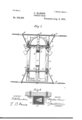
- Figure 1 represents a bottom plan view thereof; Fig. 2 a side elevation; Fig.3 alongitudinal section; Fig. 4 a front elevation.
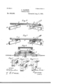
- Figs. 5, 6 and 7 are enlarged perspective views of the brace or holder employed in connection with the springs; Fig. '8 an enlarged sectional view on the line X X-, Fig. 1, showing the said brace and its relation to the spring.
- the reference letter A indicates the carriage or vehicle frame to which my improvements are shown as applied, and which may be of any preferred or convenient kind, as this does not form a material part of my invention.
- a longitudinally extending bar or beam A Secured to or forming a part of this frame is a longitudinally extending bar or beam A, which extends out below the upwardly extending front end of the frame A, and is thereat provided with the semi-circular metallic track or Way a secured to it and to the frame sides by means of suitable bolts or other fastening devices.
- the fifth-wheel a operates.
- This consists of the cross-beams B, B rigidly secured to each other by suitable fastenings, and having the semi-circular track or fifth-wheel proper a fixed thereto and arranged to bear against the track o. of the beam A.
- the fifth-wheel frame is revolubly secured to the main frame by means of the king-bolt b, which extends through the two and is fastened at its lower end by means of a suitable nut.
- a clip or holder 0 Secured to the under side of the cross-beam B directly under the point of intersection of the beam B, is a clip or holder 0 by which the front torsion spring is held in place.
- This clip has formed'in it an obliquely or diagonally extending slot 1) in which the spring 0' is secured,and the clip is held firmly and rigidly in place by means of the king-bolt b passing through it at one end and a second bolt arranged at its-remaining end.
- the spring 0' is formed of a fiat band of steel of any preferred size and strength and should be of a comparative length equal to that of the cross-beam B.
- the rods D-D are, owing to the diagonal or oblique edgewise disposition of the spring 0, normally inclined downward to a slight degree, and diverge or extend out laterally'as they project toward the axle E, whereat they are 'pivotally' secured to the upper side thereof by means of clips d of any convenient or preferred construction. It is essential to the operation of the spring 0 and its companion,which willbe described later, that its ends should notbe' confined or their torsional movements in any way limited, but to prevent lateral displacement and ICC) to aid the clips 0, braces or holders E are provided.
- braces or holders is arranged at each end of the torsion springs, and consist of the U-shaped metallic clip 6, the ends of which are when in connection with the springs O, firmly secured to the outer extremities of the beam B and project downwardly so as to surround the spring.
- a rubber bushing 6 Secured in the loop formed by the clip e, is a rubber bushing 6 provided with a peripheral groove f in which the clip lies, and a V-shaped or tri-angular recess f in its center for the reception of the spring. This arrangement is shown in detail by Figs.
- the clip 6 is shown with its upper ends bent out laterally, which form is used in connection with the rear spring as will hereinafter appear; the form of the holder E being however shown in dotted lines in Figs. 6 and 7.
- the ends of one of the springs extend, which is arranged therein so that its forward edge, which is the edge that is comparatively stationary, will extend to the angle of the recess nearest the front and rear of each holder respectively, thereby allowing the remaining edge to swing in the course of its operation, in the arc of a circle as shown in dotted lines in Fig.8.
- the rubber bushing e of holder E prevents the metallic clip c and the spring from direct contact, which would obviously result in highly injurious effects to both, for owing to the great friction between the two, they would soon wear away to such an extent as to be useless. This of course will be avoided by using the rubber bushing.
- the bushing is also used as a preventive of noise while the gear is in action and to insure a smooth and noiseless action of the parts.
- a strap-spring F Operating in conjunction with the torsion spring 0 is a strap-spring F, which is formed of a flexible strap of steel, as is the case with the torsion spring.
- the spring F is securely and rigidly fastened to the rear extremity of the beam B by means of the clip or fastening device F, and from thence it curves downwardly and proceeds directly under the clip C to the under side of the middle portion of the axle E, to which it is pivotally secured by the clip g.
- the springs provided for the rear portion of the carriage are the same in principle and contour as the springs just described the details of their fixtures only being varied to suit the different requirements arising from their different locations. They will now be described in connection with the springs C and F.
- the reference letter G indicates the rear torsion spring which is in construction and arrangement similar to the spring 0.
- G represents the clip by which the spring is held in its ed gewise diagonal position, which is in turn firmly secured to the beam A.
- the ends of the spring are confined by holders g similar in construction and functions to the holders E before described and are connected to the rods H, which are in turn pivoted to the rear axle H.
- the strap spring I is secured at its base or rigid end, to the beam A adjacent to the clip G, and has its outer end connected to the axle H at its middle, all of which is the same as the springs O and F as before explained.
- a vehicle gear the combination of an axle, a pair of rods connected to the axle, a torsion spring extending parallel with the axle and fixed at its middle to the vehicle body, the end of said spring being connected to the rods of the axle, a bearing embracing each end of the torsion spring whereby the movements of said ends are limited, the lbearing having its inner surface provided with a rubber lining for preventing friction, and a leaf-spring fixed to the vehicle body 5 and-extending longitudinally across the torision sprint, to a point directly under the axle, the axle and free end of the leaf-spring being connected, substantially as described.
Landscapes
- Engineering & Computer Science (AREA)
- Mechanical Engineering (AREA)
- Vehicle Body Suspensions (AREA)
- Springs (AREA)
Description
(No Model.)
2 Sheets-Sheet 1. C. HANSEN.
o Y. Q .1] J 1 1 I Q I FL a? I limp V I! a? I g1;
I, 2 6' ow Q /7WESSES.' lNVE/VTOR v r I B) I 5 @M. 6
2 Sheets-Sheet 2.
0. HANSEN VEHICLE GEAR.
(No Model.)
Patented Aug. 8, 1893.
INVENTOI? ATTORNEY;
WITNESSES UNITED STATES PATENT OFFICE.
CHRISTIAN HANSEN, or ROCKFORD, ILLINOIS.
VEHICLE-GEAR.
SPECIFICATION forming part of Letters Patent No. 502,905, dated August 8, 1893. Application filed April 13, 1893- Serial No. 470,190. (No model.)
To all whom itmayconcem t:
Be it known that I, CHRISTIAN HANsEN,;a citizen of the United States, residing atRockford, in the county of Winnebago and State of Illinois, haveinvented certain new and useful Improvements in Vehicle-Gears; and I do declare the following to bea full, clear, and
exact description of the invention, such as willapplied to carriages and other light vehicles,
unattended by the disadvantages which are common to all or most of the torsion springs now used.
To this end my invention consists of certain novel features of construction and com binations of parts which will be fully described hereinafter and finally embodied in the claims.
Referring to the accompanying drawings, which represent a carriage frame vto which the features of my invention are applied;
Figure 1 represents a bottom plan view thereof; Fig. 2 a side elevation; Fig.3 alongitudinal section; Fig. 4 a front elevation. Figs. 5, 6 and 7 are enlarged perspective views of the brace or holder employed in connection with the springs; Fig. '8 an enlarged sectional view on the line X X-, Fig. 1, showing the said brace and its relation to the spring.
The reference letter A indicates the carriage or vehicle frame to which my improvements are shown as applied, and which may be of any preferred or convenient kind, as this does not form a material part of my invention. Secured to or forming a part of this frame is a longitudinally extending bar or beam A, which extends out below the upwardly extending front end of the frame A, and is thereat provided with the semi-circular metallic track or Way a secured to it and to the frame sides by means of suitable bolts or other fastening devices.
In connection with this track the fifth-wheel a operates. Thisconsists of the cross-beams B, B rigidly secured to each other by suitable fastenings, and having the semi-circular track or fifth-wheel proper a fixed thereto and arranged to bear against the track o. of the beam A. The fifth-wheel frame is revolubly secured to the main frame by means of the king-bolt b, which extends through the two and is fastened at its lower end by means of a suitable nut.
The springs and their gear will now be described. Secured to the under side of the cross-beam B directly under the point of intersection of the beam B, is a clip or holder 0 by which the front torsion spring is held in place. This clip has formed'in it an obliquely or diagonally extending slot 1) in which the spring 0' is secured,and the clip is held firmly and rigidly in place by means of the king-bolt b passing through it at one end and a second bolt arranged at its-remaining end. The spring 0' is formed of a fiat band of steel of any preferred size and strength and should be of a comparative length equal to that of the cross-beam B. To secure it in position it is first passed through the slot 1) so that half of its length will occur on each side of the clip 0, and be secured therein by means of the wedge-shaped pin 0 fitting in the slit and binding against the edge of the spring on one side and the end of the slot at the other. To the extreme ends of the spring 0 a connecting bar or rod DD is secured by means of a slot 0 formed in its end which receives the end of the spring, and the 0011- nection is insured and prevented from disarrangement by means of the wedge-pin dsimilar in construction and functions to the pin 0, previously described. The rods D-D are, owing to the diagonal or oblique edgewise disposition of the spring 0, normally inclined downward to a slight degree, and diverge or extend out laterally'as they project toward the axle E, whereat they are 'pivotally' secured to the upper side thereof by means of clips d of any convenient or preferred construction. It is essential to the operation of the spring 0 and its companion,which willbe described later, that its ends should notbe' confined or their torsional movements in any way limited, but to prevent lateral displacement and ICC) to aid the clips 0, braces or holders E are provided. One of these braces or holders is arranged at each end of the torsion springs, and consist of the U-shaped metallic clip 6, the ends of which are when in connection with the springs O, firmly secured to the outer extremities of the beam B and project downwardly so as to surround the spring. Secured in the loop formed by the clip e, is a rubber bushing 6 provided with a peripheral groove f in which the clip lies, and a V-shaped or tri-angular recess f in its center for the reception of the spring. This arrangement is shown in detail by Figs. 5, 6 and 7, but in such views the clip 6 is shown with its upper ends bent out laterally, which form is used in connection with the rear spring as will hereinafter appear; the form of the holder E being however shown in dotted lines in Figs. 6 and 7. Through the openingf the ends of one of the springs extend, which is arranged therein so that its forward edge, which is the edge that is comparatively stationary, will extend to the angle of the recess nearest the front and rear of each holder respectively, thereby allowing the remaining edge to swing in the course of its operation, in the arc of a circle as shown in dotted lines in Fig.8. Apart from the function of preventing lateral or vertical displacement of the springs, the rubber bushing e of holder E prevents the metallic clip c and the spring from direct contact, which would obviously result in highly injurious effects to both, for owing to the great friction between the two, they would soon wear away to such an extent as to be useless. This of course will be avoided by using the rubber bushing. The bushing is also used as a preventive of noise while the gear is in action and to insure a smooth and noiseless action of the parts.
Operating in conjunction with the torsion spring 0 is a strap-spring F, which is formed of a flexible strap of steel, as is the case with the torsion spring. The spring F is securely and rigidly fastened to the rear extremity of the beam B by means of the clip or fastening device F, and from thence it curves downwardly and proceeds directly under the clip C to the under side of the middle portion of the axle E, to which it is pivotally secured by the clip g.
The springs provided for the rear portion of the carriage are the same in principle and contour as the springs just described the details of their fixtures only being varied to suit the different requirements arising from their different locations. They will now be described in connection with the springs C and F.
The reference letter G indicates the rear torsion spring which is in construction and arrangement similar to the spring 0. G represents the clip by which the spring is held in its ed gewise diagonal position, which is in turn firmly secured to the beam A. The ends of the spring are confined by holders g similar in construction and functions to the holders E before described and are connected to the rods H, which are in turn pivoted to the rear axle H. r
The strap spring I is secured at its base or rigid end, to the beam A adjacent to the clip G, and has its outer end connected to the axle H at its middle, all of which is the same as the springs O and F as before explained.
From the above description it will be apparent that when the carriage frame A is weighted, the springs C and F will be twisted in their respective fastenings according to the amount of weight applied, and owing to the well-known principle of the torsion spring, will resist the twisting operation, thereby giving the carriage a gentle and un dulatory action. It Will also appear that the springs F and I will assist or co-act with the the torsion springs and thereby add to the spring movement of the carriage. The operation of these springs is shown in dotted lines in Fig. 2.
Having thus described my invention, what I claim is- 1. In a vehicle gear, the combination of an axle, a pair of rods connected to the axle, a torsion spring extending parallel with the axle and fixed at its middle to the vehicle body and connected at its ends to the rods of the axle, and a leaf-spring fixed to the vehicle body and extending longitudinally across the torsion spring to a point directly under the axle, the axle and free end of the leaf-spring being connected, substantially as described.
2. In a vehicle gear, the combination of an axle, a pair of rods connected to the axle, a torsion spring extending parallel with the axle and fixed at its middle to the vehicle body, the end of said spring being connected to the rods of the axle, a bearing embracing each end of the torsion spring whereby the movements of said ends are limited, the lbearing having its inner surface provided with a rubber lining for preventing friction, and a leaf-spring fixed to the vehicle body 5 and-extending longitudinally across the torision sprint, to a point directly under the axle, the axle and free end of the leaf-spring being connected, substantially as described.
In testimony whereof I aflix my signature in presence of two witnesses.
CHRISTIAN HANSEN.
Witnesses:
JOHN BENSON, 01.01: ROHLEN.
Publications (1)
| Publication Number | Publication Date |
|---|---|
| US502905A true US502905A (en) | 1893-08-08 |
Family
ID=2571741
Family Applications (1)
| Application Number | Title | Priority Date | Filing Date |
|---|---|---|---|
| US502905D Expired - Lifetime US502905A (en) | Vehicle-gear |
Country Status (1)
| Country | Link |
|---|---|
| US (1) | US502905A (en) |
-
0
- US US502905D patent/US502905A/en not_active Expired - Lifetime
Similar Documents
| Publication | Publication Date | Title |
|---|---|---|
| US387052A (en) | Spring-vehicle | |
| US291332A (en) | Wagg-n-tonque support | |
| US597304A (en) | Body-loop for vehicles | |
| US298456A (en) | Wagon-spring | |
| US461626A (en) | John j | |
| US596313A (en) | Carriage-spring | |
| US500789A (en) | alexander | |
| US251687A (en) | Amos babnes | |
| US255461A (en) | Vehicle-spring | |
| US414395A (en) | End-gate fastening | |
| US304573A (en) | James p | |
| US466538A (en) | Vehicle-spring | |
| US117171A (en) | Improvement in buggy-springs | |
| US389869A (en) | Austin beery | |
| US204589A (en) | Improvement in vehicle spring and axle | |
| US270879A (en) | Lauren m | |
| US300254A (en) | Peteb hebeet | |
| US171864A (en) | Improvement in spring-braces for vehicles | |
| US441769A (en) | Sulky | |
| US402894A (en) | Vehicle-spring | |
| US458395A (en) | Brace for vehicle-bodies | |
| US279531A (en) | Two-wheeled vehicle | |
| US210463A (en) | Improvement in whiffletrees | |
| US218703A (en) | Improvement in trace-supporters | |
| US196041A (en) | Improvement in side-bar wagons |