US5028126A - Foldable spectacle frame - Google Patents
Foldable spectacle frame Download PDFInfo
- Publication number
- US5028126A US5028126A US07/501,035 US50103590A US5028126A US 5028126 A US5028126 A US 5028126A US 50103590 A US50103590 A US 50103590A US 5028126 A US5028126 A US 5028126A
- Authority
- US
- United States
- Prior art keywords
- lens frames
- spectacle frame
- pair
- pivot pin
- projecting
- Prior art date
- Legal status (The legal status is an assumption and is not a legal conclusion. Google has not performed a legal analysis and makes no representation as to the accuracy of the status listed.)
- Expired - Fee Related
Links
Images


Classifications
-
- G—PHYSICS
- G02—OPTICS
- G02C—SPECTACLES; SUNGLASSES OR GOGGLES INSOFAR AS THEY HAVE THE SAME FEATURES AS SPECTACLES; CONTACT LENSES
- G02C5/00—Constructions of non-optical parts
- G02C5/02—Bridges; Browbars; Intermediate bars
- G02C5/08—Bridges; Browbars; Intermediate bars foldable
Definitions
- the present invention relates to improvements in spectacle frames, and more particularly to a spectacle frame which is foldable to a flat form of the smallest possible size.
- spectacles for the aged are usually carried about and worn only for reading. Accordingly, various spectacle frames have heretofore been proposed which are portable with convenience.
- a spectacle frame which is foldable at three points as seen in FIG. 1 and which comprises a pair of lens frames hingedly connected together at the midportion therebetween, and temples of a minimum length to support the lens frames on the wearer free of trouble, i.e., a length slightly longer than the lateral width of the lens frames.
- the hinge between the lens frames is so constructed that bridges 8, 8 projecting from the inner portions 2b, 2b of the respective lens frames are movable about a vertical pivot pin 16 as shown in FIG. 8.
- the spectacle frame therefore has the problem that although it is inwardly foldable to a reduced size to the greatest possible extent, the temples 6, 6 are opposed to each other to make the folded frame bulky as shown in FIGS. 9 and 10. Consequently, a case used for accommodating the spectacles also becomes bulky, bulging the pocket of a garment when the case is placed therein.
- the present invention has been accomplished in view of the above problem.
- the main object of the present invention is to provide a spectacle frame which is foldable to a flat form of minimized size.
- the spectacle frame of the present invention comprises a pair of lens frames, a pair of temples hingedly connected to the outer portions of the respective lens frames, bridges each projecting from the inner portion of one of the lens frames toward the other lens frame, and a hinge portion provided at the forward ends of the bridges to make the lens frames inwardly foldable, the hinge portion having a pivot pin inclined at a small angle with a vertical line, so that when the spectacle frame is folded, the inner faces of the lens frames are opposed to each other with the temples opposed to the outer faces of the lens frames.
- FIG. 1 is a perspective view of a spectacle frame which is foldable at three points;
- FIG. 2 is an exploded perspective view showing a hinge portion of both brides of the spectacle frame of the invention
- FIG. 3 is a view in section taken along the line A--A in FIG. 5 and showing the hinge portion of the bridges;
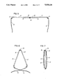
- FIG. 4 is a perspective view showing the spectacle frame of the invention as folded inward at the hinge portion;
- FIG. 5 is a plan view of the spectacle frame which is foldable at three points;
- FIGS. 6 and 7 are plan view illustrating how to fold the spectacle frame of the invention.
- FIG. 8 is a sectional view corresponding to FIG. 3 and showing the hinge portion of the bridges of a conventional spectacle frame.
- FIGS. 9 and 10 are plan views illustrating how to fold the conventional spectacle frame.
- a spectacle frame of the present invention will be described below with reference to the illustrated embodiment.
- the embodiment is given for illustrative purposes only and should not be construed as limiting the invention in any way.
- the spectacle frame of the present invention comprises a pair of lens frames 2, 2 having connectors 4, 4 at their outer portions 2a, 2a, and a pair of temples 6, 6 attached to the outer ends of the connectors 4, 4 and pivotally movable toward the inner faces of the respective lens frames 2, 2.
- a member made of rubber, silicone or like resin material can be provided on the outer end of each temple 6 for preventing slippage of the temple when the spectacles are worn.
- a bridge 8 extends from the inner portion 2b of each lens frame 2 toward the other lens frame.
- a hinge portion is provided at the forward ends of the bridges 8, 8.
- One of the bridges (the right bridge in these drawings) is formed in the vicinity of its forward end with a block 10 projecting inward.
- the block 10 has upper and lower projections 11,12 projecting from the outer end thereof inward in parallel to each other and defining a recess therebetween. As shown in FIG. 3, the projections 11, 12 are inclined at a small angle 8 with a horizontal plane.
- the other bridge (the left bridge shown) is formed in the vicinity of its forward end with a block 10 projecting inward.
- the block 10 has a projection 13 projecting from the central portion of its outer end and fitting in the recess of the right bridge. With respect to a horizontal plane, the projection 13 is inclined at the same angle ⁇ as the projections 11, 12.
- the angle of inclination is determined in accordance with the width of the lens frames 2, 2 so that the opposite connectors 4, 4 will not collide with each other when the lens frames are folded as shown in FIG. 4.
- the angle of inclination generally proposed is in the range of about 3 to about 15 degrees.
- the projection 11 is formed with a hole 11a, the projection 12 with a bore 12a extending or not extending therethrough, and the projection 13 with a hole 13a.
- a pivot pin 16 is fitted in these holes and the bore. As shown in FIG. 3, the pivot pin 16 loosely extends through the holes 11a, 13a and is screwed in the bore 12a to render the bridges 8, 8 movable about the pin 16. Instead of being screwed in the bore 12a, the pivot pin 16 can be made to extend through the bore 12a, with the projecting end fastened with a nut.
- the pivot pin 16 is inserted as inclined at the angle ⁇ with a vertical line.
- the two bridges 8, 8 bear against each other at their forward free end faces 15, 15, which therefore serve as a stopper against pivotal movement.
- the spectacle frame can be folded in the following manner. First, the lens frames 2, 2 are moved inward about the pivot pin 16, whereby the lens frames are folded as inclined relative to each other as seen in FIGS. 4 and 5. Accordingly, the connector 4 on the right lens frame is positioned below the connector 4 on the left lens frame without collision. Next, the temples 6, 6 are moved inward, whereby the spectacle frame can be folded to a flat form of minimized size as shown in FIG. 7.
- the pivot pin is preferably inclined with about 0 to 8 degrees from its vertical position, so that the spectacles can be accomodated in a case of approximately the same size as a disposable lighter and is very convenient to carry about.
- the temples are positionable over the outer faces of the lens frames and therefore serve to protect the lenses.
- the recess and the projection providing the hinge portion on the bridges can be alternatively formed on the left and right sides, respectively.
Landscapes
- Physics & Mathematics (AREA)
- Health & Medical Sciences (AREA)
- General Physics & Mathematics (AREA)
- Ophthalmology & Optometry (AREA)
- Optics & Photonics (AREA)
- Eyeglasses (AREA)
Abstract
Description
Claims (4)
Priority Applications (1)
| Application Number | Priority Date | Filing Date | Title |
|---|---|---|---|
| US07/501,035 US5028126A (en) | 1990-03-29 | 1990-03-29 | Foldable spectacle frame |
Applications Claiming Priority (1)
| Application Number | Priority Date | Filing Date | Title |
|---|---|---|---|
| US07/501,035 US5028126A (en) | 1990-03-29 | 1990-03-29 | Foldable spectacle frame |
Publications (1)
| Publication Number | Publication Date |
|---|---|
| US5028126A true US5028126A (en) | 1991-07-02 |
Family
ID=23991895
Family Applications (1)
| Application Number | Title | Priority Date | Filing Date |
|---|---|---|---|
| US07/501,035 Expired - Fee Related US5028126A (en) | 1990-03-29 | 1990-03-29 | Foldable spectacle frame |
Country Status (1)
| Country | Link |
|---|---|
| US (1) | US5028126A (en) |
Cited By (23)
| Publication number | Priority date | Publication date | Assignee | Title |
|---|---|---|---|---|
| US5208616A (en) * | 1991-10-16 | 1993-05-04 | Antony Chang | Folding spectacles |
| US5384604A (en) * | 1994-07-28 | 1995-01-24 | Chang; Tien-Tzu | Collapsible glasses |
| US5532766A (en) * | 1995-09-27 | 1996-07-02 | Al W. Paulsen | Foldable eyeglasses having locking means |
| US5764336A (en) * | 1997-02-20 | 1998-06-09 | Bausch & Lomb Incorporated | Eyewear temple crank mechanism |
| WO2000005617A1 (en) * | 1998-07-20 | 2000-02-03 | Liesegang Jose Joaquim | Spectacles frame |
| US6048061A (en) * | 1998-06-24 | 2000-04-11 | Chiu; Lien Fa | Foldable eyeglasses |
| US6375323B1 (en) * | 1998-12-23 | 2002-04-23 | Stanley Schleger | Foldable eyewear with mechanism facilitating quick opening |
| US6447116B1 (en) * | 2000-06-30 | 2002-09-10 | Contour Optik, Inc. | Folding eyeglasses |
| US20040141148A1 (en) * | 2003-01-22 | 2004-07-22 | Pin Chou | Foldable glasses |
| EP1447705A1 (en) * | 2003-02-14 | 2004-08-18 | Contour Optik Inc. | Foldable glasses |
| WO2006047923A1 (en) * | 2004-11-01 | 2006-05-11 | Yong Gao | A spectacle folded into box-shaped |
| USD692940S1 (en) * | 2013-05-20 | 2013-11-05 | Ibt Holdings, Llc | Sunglasses |
| USD697128S1 (en) * | 2013-09-23 | 2014-01-07 | Idea Village Products, Inc. | Sunglasses |
| USD702282S1 (en) * | 2013-09-23 | 2014-04-08 | IdeaVillage Products, Inc | Sunglasses |
| USD702281S1 (en) * | 2013-09-23 | 2014-04-08 | IdeaVillage Products, Inc | Sunglasses |
| USD705847S1 (en) * | 2013-05-20 | 2014-05-27 | IdeaVillage Products, Inc | Sunglasses |
| USD713444S1 (en) * | 2014-06-24 | 2014-09-16 | Neckglasses, LLC | Foldable glasses |
| USD719606S1 (en) * | 2013-09-24 | 2014-12-16 | Lvmh Swiss Manufactures Sa | Glasses |
| USD745595S1 (en) * | 2013-09-23 | 2015-12-15 | Idea Village Products Corp. | Sunglasses |
| US9541771B2 (en) | 2015-02-23 | 2017-01-10 | Microvision Optical, Llc | Dual-folding eyeglasses and eyeglass collapsible case |
| USD827700S1 (en) * | 2017-04-14 | 2018-09-04 | Neckglasses, LLC | Glasses with foldable arms |
| US10156735B2 (en) | 2015-02-23 | 2018-12-18 | Microvision Optical, Llc | Dual-folding eyeglasses and eyeglass collapsible case |
| US11409127B1 (en) | 2019-09-25 | 2022-08-09 | Roman F Coppola | Folding frame for eyeglasses |
Citations (1)
| Publication number | Priority date | Publication date | Assignee | Title |
|---|---|---|---|---|
| US2537248A (en) * | 1945-10-02 | 1951-01-09 | Vigano Gianni | Foldable spectacles |
-
1990
- 1990-03-29 US US07/501,035 patent/US5028126A/en not_active Expired - Fee Related
Patent Citations (1)
| Publication number | Priority date | Publication date | Assignee | Title |
|---|---|---|---|---|
| US2537248A (en) * | 1945-10-02 | 1951-01-09 | Vigano Gianni | Foldable spectacles |
Cited By (26)
| Publication number | Priority date | Publication date | Assignee | Title |
|---|---|---|---|---|
| US5208616A (en) * | 1991-10-16 | 1993-05-04 | Antony Chang | Folding spectacles |
| US5384604A (en) * | 1994-07-28 | 1995-01-24 | Chang; Tien-Tzu | Collapsible glasses |
| US5532766A (en) * | 1995-09-27 | 1996-07-02 | Al W. Paulsen | Foldable eyeglasses having locking means |
| EP0879438A4 (en) * | 1995-09-27 | 1999-03-24 | Paulsen Al W | Foldable eyeglasses having locking means |
| US5764336A (en) * | 1997-02-20 | 1998-06-09 | Bausch & Lomb Incorporated | Eyewear temple crank mechanism |
| US6048061A (en) * | 1998-06-24 | 2000-04-11 | Chiu; Lien Fa | Foldable eyeglasses |
| WO2000005617A1 (en) * | 1998-07-20 | 2000-02-03 | Liesegang Jose Joaquim | Spectacles frame |
| US6540349B1 (en) | 1998-07-20 | 2003-04-01 | Liesegang Jose Joaquim | Spectacles frame |
| US6375323B1 (en) * | 1998-12-23 | 2002-04-23 | Stanley Schleger | Foldable eyewear with mechanism facilitating quick opening |
| US6447116B1 (en) * | 2000-06-30 | 2002-09-10 | Contour Optik, Inc. | Folding eyeglasses |
| US6783236B2 (en) | 2003-01-22 | 2004-08-31 | Pin Chou | Foldable glasses |
| US20040141148A1 (en) * | 2003-01-22 | 2004-07-22 | Pin Chou | Foldable glasses |
| EP1447705A1 (en) * | 2003-02-14 | 2004-08-18 | Contour Optik Inc. | Foldable glasses |
| WO2006047923A1 (en) * | 2004-11-01 | 2006-05-11 | Yong Gao | A spectacle folded into box-shaped |
| USD692940S1 (en) * | 2013-05-20 | 2013-11-05 | Ibt Holdings, Llc | Sunglasses |
| USD705847S1 (en) * | 2013-05-20 | 2014-05-27 | IdeaVillage Products, Inc | Sunglasses |
| USD702281S1 (en) * | 2013-09-23 | 2014-04-08 | IdeaVillage Products, Inc | Sunglasses |
| USD702282S1 (en) * | 2013-09-23 | 2014-04-08 | IdeaVillage Products, Inc | Sunglasses |
| USD697128S1 (en) * | 2013-09-23 | 2014-01-07 | Idea Village Products, Inc. | Sunglasses |
| USD745595S1 (en) * | 2013-09-23 | 2015-12-15 | Idea Village Products Corp. | Sunglasses |
| USD719606S1 (en) * | 2013-09-24 | 2014-12-16 | Lvmh Swiss Manufactures Sa | Glasses |
| USD713444S1 (en) * | 2014-06-24 | 2014-09-16 | Neckglasses, LLC | Foldable glasses |
| US9541771B2 (en) | 2015-02-23 | 2017-01-10 | Microvision Optical, Llc | Dual-folding eyeglasses and eyeglass collapsible case |
| US10156735B2 (en) | 2015-02-23 | 2018-12-18 | Microvision Optical, Llc | Dual-folding eyeglasses and eyeglass collapsible case |
| USD827700S1 (en) * | 2017-04-14 | 2018-09-04 | Neckglasses, LLC | Glasses with foldable arms |
| US11409127B1 (en) | 2019-09-25 | 2022-08-09 | Roman F Coppola | Folding frame for eyeglasses |
Similar Documents
| Publication | Publication Date | Title |
|---|---|---|
| US5028126A (en) | Foldable spectacle frame | |
| US5760867A (en) | Double-hinged adjustable eyeglasses | |
| US6102541A (en) | Eyeglasses convertible into an eyeglass case | |
| KR100232262B1 (en) | Glasses with variable frame | |
| US5208616A (en) | Folding spectacles | |
| US4681410A (en) | Foldable eyeglasses | |
| US5828436A (en) | Eyeglass frame formed from a non-cylindrical material having resilient, deformable bellows | |
| US4840476A (en) | Compact eyeglass construction | |
| MY122432A (en) | Rimless eyeglass frame and rimless eyeglasses employing such frame | |
| US5793463A (en) | Universal attachment with moveable sideshields for eyeglasses | |
| US5640218A (en) | Foldable spectacles with temple members having deformable earpieces for fitting into compact case | |
| US6048061A (en) | Foldable eyeglasses | |
| CA2141896C (en) | Folding frameless eyeglasses | |
| KR960001800A (en) | Ear hooks for eyeglass frames | |
| JP2000180798A (en) | Folding spectacles | |
| US5225857A (en) | Collapsible glasses frames | |
| EP0056822B1 (en) | Collapsable glasses frame | |
| GB2168499A (en) | Spectacle frame | |
| US6068375A (en) | Eyeglass assembly | |
| KR100293308B1 (en) | Foldable case storage glasses | |
| KR200188390Y1 (en) | Hinge system of the spectacles frame | |
| KR200270188Y1 (en) | Structur of fold formula glasses | |
| JP2001066554A (en) | Spectacles | |
| AU602091B2 (en) | Spectacles with extractable temples | |
| KR940003919B1 (en) | Spectacles |
Legal Events
| Date | Code | Title | Description |
|---|---|---|---|
| AS | Assignment |
Owner name: TAMAKI OPTICAL CO., LTD., 17-30, KAMIKITA 9-CHOME, Free format text: ASSIGNMENT OF ASSIGNORS INTEREST.;ASSIGNOR:TAKEUCHI, YASUSHI;REEL/FRAME:005265/0846 Effective date: 19900228 |
|
| CC | Certificate of correction | ||
| FEPP | Fee payment procedure |
Free format text: PAYOR NUMBER ASSIGNED (ORIGINAL EVENT CODE: ASPN); ENTITY STATUS OF PATENT OWNER: SMALL ENTITY |
|
| FPAY | Fee payment |
Year of fee payment: 4 |
|
| FPAY | Fee payment |
Year of fee payment: 8 |
|
| REMI | Maintenance fee reminder mailed | ||
| LAPS | Lapse for failure to pay maintenance fees | ||
| STCH | Information on status: patent discontinuation |
Free format text: PATENT EXPIRED DUE TO NONPAYMENT OF MAINTENANCE FEES UNDER 37 CFR 1.362 |
|
| FP | Lapsed due to failure to pay maintenance fee |
Effective date: 20030702 |