US5025386A - Automated mail collecting and telecommunication machine II - Google Patents
Automated mail collecting and telecommunication machine II Download PDFInfo
- Publication number
- US5025386A US5025386A US07/262,029 US26202988A US5025386A US 5025386 A US5025386 A US 5025386A US 26202988 A US26202988 A US 26202988A US 5025386 A US5025386 A US 5025386A
- Authority
- US
- United States
- Prior art keywords
- item
- mailed
- coupled
- payment
- computer
- Prior art date
- Legal status (The legal status is an assumption and is not a legal conclusion. Google has not performed a legal analysis and makes no representation as to the accuracy of the status listed.)
- Expired - Lifetime
Links
Images


Classifications
-
- G—PHYSICS
- G07—CHECKING-DEVICES
- G07F—COIN-FREED OR LIKE APPARATUS
- G07F17/00—Coin-freed apparatus for hiring articles; Coin-freed facilities or services
- G07F17/0014—Coin-freed apparatus for hiring articles; Coin-freed facilities or services for vending, access and use of specific services not covered anywhere else in G07F17/00
-
- G—PHYSICS
- G07—CHECKING-DEVICES
- G07B—TICKET-ISSUING APPARATUS; FARE-REGISTERING APPARATUS; FRANKING APPARATUS
- G07B17/00—Franking apparatus
- G07B17/00185—Details internally of apparatus in a franking system, e.g. franking machine at customer or apparatus at post office
- G07B17/00193—Constructional details of apparatus in a franking system
-
- G—PHYSICS
- G07—CHECKING-DEVICES
- G07F—COIN-FREED OR LIKE APPARATUS
- G07F17/00—Coin-freed apparatus for hiring articles; Coin-freed facilities or services
- G07F17/26—Coin-freed apparatus for hiring articles; Coin-freed facilities or services for printing, stamping, franking, typing or teleprinting apparatus
-
- G—PHYSICS
- G07—CHECKING-DEVICES
- G07B—TICKET-ISSUING APPARATUS; FARE-REGISTERING APPARATUS; FRANKING APPARATUS
- G07B17/00—Franking apparatus
- G07B17/00016—Relations between apparatus, e.g. franking machine at customer or apparatus at post office, in a franking system
- G07B17/0008—Communication details outside or between apparatus
- G07B2017/00088—Communication details outside or between apparatus via landlines
- G07B2017/00096—Communication details outside or between apparatus via landlines via phone lines
-
- G—PHYSICS
- G07—CHECKING-DEVICES
- G07B—TICKET-ISSUING APPARATUS; FARE-REGISTERING APPARATUS; FRANKING APPARATUS
- G07B17/00—Franking apparatus
- G07B17/00016—Relations between apparatus, e.g. franking machine at customer or apparatus at post office, in a franking system
- G07B17/0008—Communication details outside or between apparatus
- G07B2017/00153—Communication details outside or between apparatus for sending information
- G07B2017/00177—Communication details outside or between apparatus for sending information from a portable device, e.g. a card or a PCMCIA
-
- G—PHYSICS
- G07—CHECKING-DEVICES
- G07B—TICKET-ISSUING APPARATUS; FARE-REGISTERING APPARATUS; FRANKING APPARATUS
- G07B17/00—Franking apparatus
- G07B17/00185—Details internally of apparatus in a franking system, e.g. franking machine at customer or apparatus at post office
- G07B17/00193—Constructional details of apparatus in a franking system
- G07B2017/00225—Vending machine or POS (Point Of Sale) apparatus
-
- G—PHYSICS
- G07—CHECKING-DEVICES
- G07B—TICKET-ISSUING APPARATUS; FARE-REGISTERING APPARATUS; FRANKING APPARATUS
- G07B17/00—Franking apparatus
- G07B17/00459—Details relating to mailpieces in a franking system
- G07B17/00508—Printing or attaching on mailpieces
- G07B2017/00572—Details of printed item
- G07B2017/0058—Printing of code
- G07B2017/00588—Barcode
Definitions
- the present invention relates to electronic postage meters of the type having a microprocessor for controlling envelope stamping and the accounting for such stamping, and for the efficient and economical franking of letters. It also relates to motorized weighing conveyors mounted on an electronic weighing device and to electronic scales with the ability to print bar code labels. It further relates to printers able to print data entered on an alphanumerical keyboard in the form of laser readable bar code and to vending machines with the ability to accept payment in coins, bills, and debit, credit, or IC cards. It also relates to coin, and debit, or credit card operated pay-phones, various devices used for the listing of data from some external database, and to telex machines.
- the present invention relates to my copending U.S. patent application Ser. No. 226,777, filed Aug. 1, 1988, entitled "Automated Electronic Postage Meter Having a Direct Access Bar Code Printer.”
- An object of the present invention is to provide an automated machine for the collection and stamping of mail.
- Electronic postage metering and stamping machines will be discussed first.
- Conventional postage metering and stamping machines have the ability to electronically weigh envelopes, package mailings, and to stamp the postage on an envelope. They are operated by an employee and the postage is determined according to the envelope's weight and its destination. The postage can either be debited from the machine's previously charged non-volatile memory or paid in cash to the employee when the machine is used in postal offices. These machines do not significantly affect the further sorting and tracking process.
- Another object of the present invention is to improve the entire mailing process from the point of acceptance to the point of delivery for almost all kinds of postcards, envelopes, and packages, referred to as "a” or “the” "mailing” in this text.
- the advantages of the invention will be listed further.
- the present invention enables mail collecting procedures to be performed directly by a customer who inserts the mailing and manually enters the instructions and data on a keyboard by following the displayed instructions. Therefore, there is no need for any employees to operate the present invention.
- a customer himself chooses and performs the payment procedure by using one of the possible payment modes.
- the machine can also be installed anywhere for the most convenient and continuous customer usage.
- the present invention enables the electronic weighing of a mailing to be performed automatically and securely, without the possibility for a customer to influence the weighing, and the postage is automatically calculated according to the mailing weight data and the destination data entered on the keyboard. Therefore, according to the process of the present invention, there is no possibility for a higher or lower postage being calculated and since each mailing can be returned to the customer in the case of insufficient postage paid or data entered, no further check as to whether the postage was paid is necessary.
- the present invention enables the entire further sorting and tracking process to be performed by automated means.
- multidirectional scanners built-in on both sides of the mailing path at the sorting hubs, each mailing can be sorted and tracked, when required, without any manual labor involved and with extremely high speed and an almost 100% first read rate.
- the mailing when the destination zip code is printed on a mailing in a form of said bar code, the mailing can be automatically sorted all the way to the point of delivery by passing through the different sorting hubs.
- a Zip+four code can also be applied and when an alphanumeric type of bar code is used, the mailing can be sorted and tracked in international mail traffic. This assumes that the part of the printed bar code showing the mailing's zip code is printed in numerals and that the part of the bar code showing the country code is printed in letters so that a combination of two letters represents the country code of each respective country.
- the bar code is printed on the mailing with the letters and numerals arranged according to how they were entered in on the machine's keyboard.
- an identification code in numerals is automatically printed together with the type of special request which information is printed using a letter or letters on the same line with the country and zip code.
- Yet another object of the present invention is to provide a pay-phone device for public use.
- conventional pay-phones will be discussed.
- pay-phones for public use are designed to accept payment means, such as coins, and debit or credit cards, and most of them are able to accept only one out of the three said means.
- the same displaying and processing means are used and this enables the device to be economical while giving the customer all possible options of mode of payment.
- Still another object of the present invention is to provide a device for listing the data of, and entering into some external database.
- Various kinds of databases are available for the listing and entering of data using various means, mostly by connecting existing home or corporate PCs and using them as terminals to list the data available in a certain database for a certain predetermined charge.
- an object of the present invention is to provide a device which will make the data from some external database available to the general public.
- a continuous, convenient, and economical data listing and data entry operation can be obtained.
- a variety of data can be listed, such as data from a phone-book, a Yellow Pages, a Thomas Register, weather report data, and train, bus, and plane schedules, etc., and in addition to getting a listing, a customer can be allowed to enter data into the database for certain purposes, such as for making reservations, etc.
- a further object of the present invention is to provide a device where, when the device is connected to a telex line, a telex message can be sent by using the same procedure as that used in an existing telex machine, with the difference that the message is not printed and dispensed to the customer if this is not specifically requested.
- a message entered on a keyboard is memorized and, upon confirmation of payment for a calculated and displayed charge, sent on. This enables the general public to send messages whenever desired to any connected telex and since the same data entry, payment acceptance, display, printing, and processing means as for the machine's other purposes are used, this procedure also becomes very economical.
- means for accepting payment either in coins, bills, or debit, credit, or IC cards, means for entering any required data, means for displaying said data and the instructions for the use of the machine during the different phases of the process, means for printing, dispensing, processing, and storing the required data, wherein all said means are used for all of the machine's various functions.
- means for the inserting, driving, pressing, bar code printing, and the storing of the mailing, used for the machine's mail collection purpose which is one object of the present invention.
- the machine is able to accept postcards, envelopes, and postal packages, weigh them by an electronic means, print destination data on them in a chosen form of laser readable bar code for the purposes of later completely automatically sorting and tracking the mailing, and store them for subsequent pick up.
- One of the objects of the present invention is the use of the machine as a pay-phone device which would accept the payment of any charges by all the previously discussed payment means.
- the machine has to be connected to a telephone line which is also used as the connection to any external databases when the machine is used as a data listing device, which is yet another object of the present invention.
- the machine When used as a telex sending device, which is a further object of the present invention, the machine has to be connected to a telex line.
- FIG. 1 is a perspective view of the machine housing showing the outside arrangement of its parts as disclosed by an embodiment of this invention.
- FIG. 2 is a left side view of the machine housing showing the insertion slot's sliding door, dot matrix printer opening, liquid crystal display (“LCD”), keyboard and phone handle.
- LCD liquid crystal display
- FIG. 3 is a left side view of the machine's inside mechanisms, showing the mailing pressing mechanism, electronic scale device, insertion slot's rear wall, thermal transfer printing mechanism, transport conveyor mechanism, mailing drop, dot matrix printer, LCD and keyboard.
- FIG. 4 is a top view of the machine's inside mechanisms.
- FIG. 5 is a perspective view of the thermal transfer printer configuration located behind the insertion slot's rear wall.
- FIG. 6 is a perspective view of the mailing pressing mechanism and transport conveyor mechanism.
- FIG. 7 is a perspective view of the insertion slot's rear wall, loading photosensors and transport conveyor mechanism.
- FIG. 8 is an example of a bar code as it would be printed on a mailing sent abroad, i.e., to Hamburg in the Federal Republic of Germany by registered mail, having the country of destination code (D for FRG), zip code (2000 for Hamburg and 13 for certain section in Hamburg), special request code (R for registered mail) and numeral-letter combination (000A for mailing identification).
- D country of destination code
- R special request code
- 000A numeral-letter combination
- FIG. 9 is an example of a bar code as it would be printed on a mailing sent by regular mail to East Hanover, N.J., U.S.A., having the country of destination code (U.S. for U.S.A.) and zip code (07936 for East Hanover).
- FIG. 10 is a block diagram of the machine in accordance with the present invention.
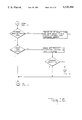
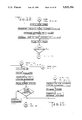
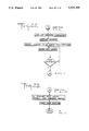
- FIGS. 11 to 23 are flow charts showing the process of the machine as disclosed by the present invention.
- the present invention can be installed as a completely independent unit, its processes will be described on the assumption that the machine is connected to telephone and telex lines.
- FIG. 1 illustrates one embodiment of the present invention.
- a coin changer 2 with escrow to vend/escrow to select ability
- a bill acceptor/validator 3 with escrow to vend/escrow to select ability
- a magnetic and IC card reader/writer 4 with escrow to vend/escrow to select ability
- a dot matrix printer 5 with an opening 51 for refilling with paper and ribbon
- an alphanumerical keyboard 6 a liquid crystal display (LCD) 8, a transparent glass window 7, a phone handle dialing unit 10, and an insertion slot's sliding door 120 all built into machine housing 1.
- LCD liquid crystal display
- the machine's front-placed photo sensor 9 is also built into machine housing 1 and upon detecting a person standing in front of the housing 1 indicates this to the machine's central processing unit ("CPU") 32 which causes a wake-up routine to occur.
- CPU central processing unit
- CPU 32 starts by reading the status of the coin changer 2 and if changer 2 activity is detected, the accumulated amount in escrow is counted, the information is loaded into temporary memory unit 34, and the balance is displayed on LCD 8. If no changer 2 activity is detected, CPU 32 reads the status of the bill acceptor/validator 3, which upon bill insertion automatically checks the bill's validity and, if the bill is valid, drives it into escrow. If this is the case, the bill is held in escrow, the accumulated amount is counted, the information is loaded into temporary memory unit 34, and the balance is displayed on LCD 8. If after a reasonable period of time the amount in escrow, either in bills or in coins, is still lower than requested, a request for additional fund insertion is displayed. If within a reasonable period of time an additional amount is not inserted, the amount in escrow is returned and the machine goes back to the starting procedure as shown in FIG. 11.
- the status of the magnetic and IC card reader/writer 4 is read, as shown in FIG. 11, and if any card is inserted, the procedure is continued, as shown in FIG. 12, to identify what kind of a card was inserted. If the inserted card is identified as a credit card, the machine checks the card's validity and if it is not valid returns it by the procedure shown in FIG. 12. The procedure further includes a check of whether the card is one with or without a PIN (Personal Identification Number). If the card has a PIN, a request to enter the PIN is displayed.
- PIN Personal Identification Number
- the card is kept inside the reader/writer 4 until the entire process is completed.
- the company identification is checked and, if correct, the machine continues the procedure by checking whether a minimum amount exists on the card as shown in FIG. 13. If a minimum amount exists, the machine enables the process to continue, holding the card until the process is finished. If, however, any of the checks do not comply with the requirements, the card is returned and the process is suspended as shown in FIG. 13. After any initial minimum amount requirement is satisfied, the machine can continue the process for any of the machine's functions. The mail collection process will be described first.
- FIGS. 1, 4, and 14 if a customer enters an instruction that the mail collection process is desired, the instruction on how to insert a mailing is displayed on LCD 8 and the solenoid 13 opens the insertion slot's sliding door 120 as shown in FIG. 4. The customer then inserts the mailing into the scale insertion slot 12, FIG. 4.
- the loading photosensor 30, FIG. 7, detects the incoming mailing electric motor 23 is activated to drive transport conveyor 25 which turns over its transmission cylinders 29, FIG. 7, and carries the mailing toward the right border of the insertion slot 12.
- the second loading photosensor 31, FIG. 7, detects the mailing's edge electric motor 23 stops, thereby causing transport conveyor 25 to stop leaving the mailing positioned in front of the printing window 122, as shown in FIGS. 4, 5 and 7, and behind the mailing pressing panel 16, as shown in FIGS. 3, 4 and 6.
- the insertion slot 12, transport conveyor mechanisms 23, 25, 27, and 29, and the mailing pressing mechanisms 14, 15, and 16 are all mounted on insertion slot's rear wall 121 which is hung on electronic scale device 24 so that they do not influence the weight calculation of the mailing during the mailing procedure.
- the scale weighing device 24 is activated and the mailing weight data is then loaded into the temporary memory unit 34. Simultaneously, instructions on how to enter the required data about the mailing's destination on keyboard 6 are displayed and the customer has to enter this data.
- the customer can read this data from the face of the mailing because the mailing has to be inserted in such a way that the address written on its face comes behind transparent glass window 7 and transparent mailing pressing panel 16 and can be read from outside of the machine after the mailing is driven inside the insertion slot 12.
- the data to be entered on keyboard 6 may comprise the mailing's country of destination, the zip code, and a variety of special requests such as registered mail, express mail, etc., or any other data required by company standards.
- FIG. 14 according to the data about the mailing weight, the data about the destination and about any special requests, and based on any instructions stored in the machine's memory, a charge is calculated and displayed together with a request for an additional payment if the amount in escrow is not sufficient to cover the charge.
- the customer is asked to insert an additional amount and if the request is not fulfilled after a second displayed warning, the mailing and any already inserted cash are returned.
- the transport conveyor 25 is rotated counterclockwise to drive the mailing out of insertion slot 12 through insertion slot's sliding door 120 which is opened by its solenoid 13.
- the machine continues the procedure as shown in FIG. 16. If the existing credit on the debit card is not sufficient, an additional amount can be inserted in cash or paid by a new debit card after the first card is debited to zero. If, however, the request is not fulfilled, the machine continues the above described returning procedure as shown in FIG. 18. For payment with a credit or IC card, as shown in FIG. 16, the data about the card and any corresponding charge is loaded into temporary memory unit 34 in order to be stored and forwarded for the purposes of later billing.
- the machine continues the procedure, as shown in FIG. 17, by activating the mailing pressing unit's electric motor 14, FIGS. 3, 4 and 6, which, by using the transmission mechanism 15, pushes forward the transparent pressing panel 16.
- the panel 16 presses the mailing to the insertion slot's rear wall 121 and firmly secures it there so that the rear side of the mailing leans against printing window 122, FIGS. 4, 5 and 7, in a flat fashion so that the bar code can be printed.
- the entered destination data is converted into a chosen form of laser readable bar code and when the mailing is pressed, the thermal transfer printing head 21, shown in FIGS. 3, 4 and 5 prints the bar code on the part of the mailing which leans against the printing window 122 as shown in FIGS. 4, 5 and 7.
- the thermal transfer printing configuration comprises four lateral holders built on the machine's base, wherein the two holders 22 are used to support the configuration carriers 18 which are driven up and down over the two indented holders 19 by indented axle built-in stepping motor 17.
- the configuration further comprises a stepping motor 20 which over supporting bars built-in two said carriers 18, drives the thermal transfer printing head 21 left and right.
- the bar code is printed by the head 21 during its left to right movement. When the head 21 reaches the right printing margin, the carriers 18 move one step downward and carry the head 21 to the next line printing position. According to the described procedure, the bar code is printed on the stationary mailing by moving the printing head 21 in all four possible directions.
- the country code when using alphanumeric type bar code, can be printed as a combination of two letters (e.g., D for Federal Republic of Germany), the zip code in numerals (e.g., 2000 for Hamburg in FRG and 13 for certain section of Hamburg), and the special request code as a single letter (e.g., R for registered mail) with the assumption that when a special request is entered, the machine automatically prints an identification number (e.g., 000A).
- the identification code is printed using alphanumeric combinations starting with zeros and terminating with Zs (i.e., from 0000 to ZZZZ). These alphanumeric combinations yield 36 to the "nth" power combination where "n" can be determined in accordance with requirements.
- FIG. 9 An example of a bar code for a mailing sent by regular mail is shown in FIG. 9.
- Such bar code consists of a country of destination code (U.S. for U.S.A.) and zip code.
- the date of acceptance and postage paid can also be printed in human readable characters under the bar code if required.
- any type of laser readable bar code can be used and arranged in any form depending on which code and arrangement is proven to be the most suitable for the purposes of later tracking and scanning. Considering the fact that not all countries have numerical zip codes and that the country code and special request code can be simply formed as a combination of letters, alphanumeric CODE-39 as shown appears to be the most suitable. It is also to be understood that some other printing means can be used instead of the thermal transfer printing head which seems to be the most suitable considering the costs and the bar code quality required.
- the printing head 21 After the bar code printing procedure is completed, the printing head 21 returns to its starting position and the pressing panel 16 returns backward, leaving the mailing on transport conveyor 25 which, according to the process of the invention as shown in FIG. 17, is driven downward by the electric motor 27, shown in FIGS. 3, 4 and 6.
- Electric motor 27, mounted on insertion slot's rear wall turns the entire transport conveyor configuration, which comprises transport conveyor 25, electric motor 23 and cylinders 29, shown in FIGS. 3, 4, 6 and 7, up and down.
- electric motor 27 turns the conveyor configuration back to its starting position.
- the machine displays instructions on how one can continue the process by entering directions for a "follow on” procedure which can be entered when another of the machine's services is required as shown in FIG. 17. If no "follow on” directions are entered, the machine continues the procedure by printing and dispensing a receipt from its dot matrix printer 5 in the case of a mailing with a special request, taking the charged amount from escrow and returning the change or the card, FIG. 17, and loading or transferring the relevant data as shown in FIG. 23.
- the machine can either load all relevant data on a disk in its disk drive unit 11, FIG. 4, for later use or, when connected to some external database, transfer it to that database for later use.
- FIG. 1 Another function of the present invention is as a pay-phone device wherein the same previously described payment accepting and displaying means are used.
- FIG. 1 there is shown a phone handle 10 hung on machine housing 1, comprising a phone unit connected to a phone line through the housing 1 and including a dialing keyboard inside its middle section.
- FIG. 11 if there is no minimum amount required for using the machine as a pay-phone device, as soon as any amount is inserted, the customer can pick up the phone handle 10 and get a dial tone.
- the card validity checking procedure corresponds to the one previously described for the machine's mail collection function and as shown in FIGS. 12 and 13.
- the machine continues the procedure by displaying instructions on how to dial the desired number.
- the number is permanently displayed as dialed in order to avoid the dialing of a wrong number.
- the machine continues by displaying information on whether the number was connected and instructions on how to repeat the dialing procedure if the desired number is not obtained.
- the remaining credit is permanently displayed and the line remains connected for as long as the credit equals zero, as shown in FIG. 20.
- the accumulated charge is permanently displayed and the line can be disconnected if a certain given limit is reached. Referring now to FIG. 20, if the line is disconnected by the customer before the credit equals zero or the limit is not reached, the customer has the opportunity to enter directions for a "follow on" procedure before any change from escrow or a card is returned, as shown in FIG. 22, after which the machine continues the procedure as shown in FIG. 23.
- the invention can also be used as a data listing and data entry device which uses the same payment making, data entering, data displaying, and data printing means as discussed previously.
- the payment procedure for an initial minimum amount corresponds to the one previously described for the machine's use as a mail collecting device.
- FIG. 19 when a customer enters the direction that a connection with a database is desired, the information on how to obtain a connection with that certain database is displayed on LCD 8.
- the payment procedure in this case corresponds to the one described for use of the machine as a pay-phone device, with the assumption that the charge per time unit (seconds) is higher than in the previous case.
- the customer can enter data into the database by using the machine's keyboard 6.
- Different reservation, purchasing, or advertising procedures can be performed by using this process which allows for convenient and economical access to various databases for the general public.
- the present invention can also be used as a telex sending device for the purpose of sending messages to any desired telex number.
- the same payment making, data entering, data displaying, and printing means as described previously can be used. Referring now to FIGS. 11, 12, and 13, the payment procedure for an initial minimum amount corresponds to the procedure previously described for the machine's other functions. If the customer enters an instruction that a telex connection is desired, instructions on how to print a message and the destination are displayed on LCD 8 as shown in FIG. 21. The customer enters a message and destination number which are simultaneously displayed on LCD 8 and which can be corrected before entering the instruction that the message is completed.
- the charge is calculated and displayed for the customer together with a request for an additional amount of payment if the amount in escrow is not sufficient to cover the charge.
- a warning is also displayed and if the request is not fulfilled following the displayed warning, the message is erased and the inserted amount or the card are returned according to the procedure shown in FIG. 22. If the payment is correctly made, instructions on how to enter an execute order are displayed as shown in FIG. 21 and upon this order, the machine automatically dials the desired number and sends the entered message.
- the machine continues the dialing procedure for a certain period of time while keeping the message memorized until it determines that the number is not obtainable, upon which time the message is erased and the cash or card returned as shown in FIG. 22.
- the message is sent and erased from the machine's memory. If, however, the customer wants the message to be printed and has previously entered this instruction, the machine prints the message on its dot matrix printer 5 and dispenses it to the customer as it is being sent. Change from escrow or the inserted card is returned according to the procedure shown in FIG. 22 unless a "follow on" direction is entered by the customer.
- the data storing or forwarding procedures and the change or card returning procedures are identical, regardless of the machine's function, to those shown in FIGS. 22 and 23.
- a receipt for charges paid is printed and dispensed to customer.
- a customer can always correct any entered data immediately by moving the pointer over the displayed text.
Abstract
Description
Claims (19)
Priority Applications (3)
| Application Number | Priority Date | Filing Date | Title |
|---|---|---|---|
| US07/262,029 US5025386A (en) | 1988-08-01 | 1988-10-25 | Automated mail collecting and telecommunication machine II |
| PCT/US1989/004456 WO1990004824A1 (en) | 1988-10-25 | 1989-10-06 | Automated mail collecting and telecommunication machine |
| CA002000682A CA2000682C (en) | 1988-10-25 | 1989-10-13 | Automated mail collecting and telecommunication machine ii |
Applications Claiming Priority (2)
| Application Number | Priority Date | Filing Date | Title |
|---|---|---|---|
| US07/226,778 US4900905A (en) | 1988-08-01 | 1988-08-01 | Automated mail collecting and telecommunication machine |
| US07/262,029 US5025386A (en) | 1988-08-01 | 1988-10-25 | Automated mail collecting and telecommunication machine II |
Related Parent Applications (1)
| Application Number | Title | Priority Date | Filing Date |
|---|---|---|---|
| US07/226,778 Continuation-In-Part US4900905A (en) | 1988-08-01 | 1988-08-01 | Automated mail collecting and telecommunication machine |
Publications (1)
| Publication Number | Publication Date |
|---|---|
| US5025386A true US5025386A (en) | 1991-06-18 |
Family
ID=22995883
Family Applications (1)
| Application Number | Title | Priority Date | Filing Date |
|---|---|---|---|
| US07/262,029 Expired - Lifetime US5025386A (en) | 1988-08-01 | 1988-10-25 | Automated mail collecting and telecommunication machine II |
Country Status (3)
| Country | Link |
|---|---|
| US (1) | US5025386A (en) |
| CA (1) | CA2000682C (en) |
| WO (1) | WO1990004824A1 (en) |
Cited By (43)
| Publication number | Priority date | Publication date | Assignee | Title |
|---|---|---|---|---|
| WO1992017861A1 (en) * | 1991-04-01 | 1992-10-15 | Pi Electronics Incorporated | Automated self-service package shipping machine |
| WO1992018949A1 (en) * | 1991-04-10 | 1992-10-29 | U-Ship International, Ltd. | System for mailing and collecting items |
| US5293030A (en) * | 1991-03-09 | 1994-03-08 | Francotyp-Postalia Gmbh | Method and device for processing mail |
| US5309363A (en) * | 1992-03-05 | 1994-05-03 | Frank M. Graves | Remotely rechargeable postage meter |
| US5369221A (en) * | 1991-04-10 | 1994-11-29 | U-Ship, Usa, Ltd. | System for mailing and collecting items |
| US5586037A (en) * | 1991-04-01 | 1996-12-17 | Pi Electronics, Inc. | Automated self-service mail processing and storing systems |
| DE19605015C1 (en) * | 1996-01-31 | 1997-03-06 | Francotyp Postalia Gmbh | Device for printing on print carrier standing on edge e.g. letter in franking or addressing machine |
| DE19605014C1 (en) * | 1996-01-31 | 1997-03-13 | Francotyp Postalia Gmbh | Printing device for postal franking or addressing machine |
| EP0779601A2 (en) | 1995-12-14 | 1997-06-18 | Francotyp-Postalia AG & Co. | Method for paying the resetting of an electronic franking machine and arrangement for operating a data host |
| EP0788073A2 (en) | 1996-01-31 | 1997-08-06 | Francotyp-Postalia Aktiengesellschaft & Co. | Device for printing a printing support standing on an edge |
| EP0787586A1 (en) * | 1994-10-20 | 1997-08-06 | Omron Corporation | Printing device and postage franking machine |
| US5656799A (en) * | 1991-04-10 | 1997-08-12 | U-Ship, Inc. | Automated package shipping machine |
| EP0789332A2 (en) | 1996-01-31 | 1997-08-13 | Francotyp-Postalia AG & Co. | Device for printing a printing support standing on an edge |
| US5712787A (en) * | 1995-07-10 | 1998-01-27 | Canada Post Corporation | Electronic postal counter |
| US5715164A (en) * | 1994-12-14 | 1998-02-03 | Ascom Hasler Mailing Systems Ag | System and method for communications with postage meters |
| US5728998A (en) * | 1996-03-29 | 1998-03-17 | Motorola, Inc. | Secure smart card reader with virtual image display and pull-down options |
| DE19740395A1 (en) * | 1997-09-05 | 1999-03-11 | Francotyp Postalia Gmbh | Print carrier transport and imprinting arrangement |
| EP0903244A2 (en) | 1997-09-05 | 1999-03-24 | Francotyp-Postalia AG & Co. | Printing Device and Method for the Printout on a Printing Medium |
| EP0944028A2 (en) | 1998-03-18 | 1999-09-22 | Francotyp-Postalia AG & Co. | Method for a franking and address printing machine |
| EP0961236A2 (en) | 1998-05-15 | 1999-12-01 | Francotyp-Postalia Aktiengesellschaft & Co. | Apparatus for printing mailpieces |
| EP1073018A1 (en) | 1999-07-30 | 2001-01-31 | Francotyp-Postalia AG & Co. | Pre-payment and post-payment franking machine |
| US6224187B1 (en) * | 1997-06-18 | 2001-05-01 | Francotyp Postalia Ag & Co. | Device for positioning an ink jet print head and a cleaning and sealing device |
| WO2001037712A2 (en) * | 1999-11-24 | 2001-05-31 | Brivo Systems, Inc. | Method for outbound shipment of packages direct from home or office using an unattended transfer device |
| US20020029153A1 (en) * | 1999-06-24 | 2002-03-07 | Pitney Bowes Inc. | Method and apparatus for tracking a special service delivery of a mail item created by an office worker |
| WO2002021421A1 (en) * | 2000-09-08 | 2002-03-14 | United States Postal Service | Systems and methods for redirecting items in a delivery system |
| DE19925681C2 (en) * | 1998-05-15 | 2002-09-12 | Francotyp Postalia Ag | Device for printing postal matter |
| US20030028458A1 (en) * | 2000-06-28 | 2003-02-06 | Joel Gaillard | System and method to accomplish a transaction |
| US20030182155A1 (en) * | 2002-03-20 | 2003-09-25 | David Nitzan | Method and apparatus for handling mail pieces that require special handling |
| US20030182154A1 (en) * | 2002-03-20 | 2003-09-25 | Myers Gregory K. | Method and apparatus for handling mail pieces that require special handling |
| US20030217018A1 (en) * | 2002-05-17 | 2003-11-20 | Groff Jason J. | System and method for conducting a shipping transaction |
| US20030230436A1 (en) * | 2002-04-16 | 2003-12-18 | Styrbjorn Garde | Automatic mailing machine and method of handling postal items |
| US20040059675A1 (en) * | 2001-03-16 | 2004-03-25 | Joel Gaillard | System and method for replacing identification data on a portable transaction device |
| US20040089482A1 (en) * | 1991-04-10 | 2004-05-13 | Uship Intellectual Properties, Llc | Automated package shipping machine |
| US20050108111A1 (en) * | 2003-11-17 | 2005-05-19 | Kranyec Stephen L. | Mailing kiosk with safeguards and methods of use |
| US6917924B1 (en) | 1991-04-10 | 2005-07-12 | Uship Intellectual Properties, Llc | Automated package shipping machine |
| US6997374B2 (en) | 2001-11-29 | 2006-02-14 | Lockheed Martin Corporation | Apparatus for testing for particulate contaminants in depositories for mail-like articles |
| NL1029623C2 (en) * | 2004-07-27 | 2006-12-05 | Neopost Ind Sa | Print using moving print heads. |
| US20080148970A1 (en) * | 2006-12-20 | 2008-06-26 | Palo Alto Research Center Incorporated | Document processing devices, systems and methods thereof |
| US7617112B2 (en) | 2005-08-29 | 2009-11-10 | Harrison Jr Shelton E | Postal system, method and device |
| US20100128072A1 (en) * | 2008-11-26 | 2010-05-27 | Andreas Wagner | Universally usable electronic manual stamping device |
| CN103927641A (en) * | 2014-04-11 | 2014-07-16 | 高恬溪 | Self-service express pickup system and method based on O2O logistics platform |
| US20150148210A1 (en) * | 2012-06-06 | 2015-05-28 | Services De Marketing Sibthorpe Inc. | Assembly for custom box blank preparation and method |
| US9478094B2 (en) | 2009-12-29 | 2016-10-25 | Pitney Bowes Inc. | Postal services kiosk having payment card security |
Families Citing this family (7)
| Publication number | Priority date | Publication date | Assignee | Title |
|---|---|---|---|---|
| US5313404A (en) * | 1986-10-17 | 1994-05-17 | Wu Sheng J | Automatic postal teller machine |
| CA2049407A1 (en) * | 1990-08-20 | 1992-02-21 | Wu Sheng-Jung | Automatic mail-processing device with full functions |
| FR2667422A1 (en) * | 1990-09-28 | 1992-04-03 | Necco Gilbert | METHOD AND APPARATUS FOR AUTOMATIC POSTAGE FOR THE PAYMENT OF TAXES. |
| DE4034292A1 (en) * | 1990-10-25 | 1992-04-30 | Francotyp Postalia Gmbh | METHOD FOR MAILING POSTAGE AND ARRANGEMENT FOR CARRYING IT OUT |
| GB2274622B (en) * | 1993-01-29 | 1996-05-08 | Neopost Ltd | Mail handling apparatus |
| IT1261584B (en) * | 1993-09-09 | 1996-05-23 | Olivetti & Co Spa | ELECTRONIC POSTAGE ITEMS OF POSTAGE |
| WO2007088414A1 (en) * | 2006-02-03 | 2007-08-09 | Al Jenaibi Abdulla Hamad Saeed | Automatic mail sending machine for the automatic po box |
Citations (12)
| Publication number | Priority date | Publication date | Assignee | Title |
|---|---|---|---|---|
| US4024380A (en) * | 1971-01-18 | 1977-05-17 | Damon Mott Gunn | Self service postal apparatus and method |
| US4439636A (en) * | 1982-03-09 | 1984-03-27 | Martha Newkirk | Credit card actuated telecommunication access network |
| US4511793A (en) * | 1983-04-04 | 1985-04-16 | Sylvester Racanelli | Mail metering process and machine |
| US4722430A (en) * | 1984-02-03 | 1988-02-02 | Francesco Canziani | Carriage for sorting-machines in particular, with independently actioned tiltable plate |
| US4756399A (en) * | 1984-02-24 | 1988-07-12 | Meccanizzazione Postale E Automazione S.P.A. | Belt conveyor for the sorting of sundry articles |
| US4796193A (en) * | 1986-07-07 | 1989-01-03 | Pitney Bowes Inc. | Postage payment system where accounting for postage payment occurs at a time subsequent to the printing of the postage and employing a visual marking imprinted on the mailpiece to show that accounting has occurred |
| US4800506A (en) * | 1987-03-13 | 1989-01-24 | Pitney Bowes Inc. | Apparatus for preparing mail pieces |
| US4802218A (en) * | 1986-11-26 | 1989-01-31 | Wright Technologies, L.P. | Automated transaction system |
| US4837701A (en) * | 1985-12-26 | 1989-06-06 | Pitney Bowes Inc. | Mail processing system with multiple work stations |
| US4853869A (en) * | 1987-03-13 | 1989-08-01 | Pitney Bowes, Inc. | System and method for processing a letter for bulk mailing |
| US4878574A (en) * | 1985-08-14 | 1989-11-07 | Gustav Wagner Maschinenfabrik Gmbh & Co. Kg | Apparatus for sorting workpieces |
| US4900905A (en) * | 1988-08-01 | 1990-02-13 | Pavo Pusic | Automated mail collecting and telecommunication machine |
-
1988
- 1988-10-25 US US07/262,029 patent/US5025386A/en not_active Expired - Lifetime
-
1989
- 1989-10-06 WO PCT/US1989/004456 patent/WO1990004824A1/en unknown
- 1989-10-13 CA CA002000682A patent/CA2000682C/en not_active Expired - Lifetime
Patent Citations (12)
| Publication number | Priority date | Publication date | Assignee | Title |
|---|---|---|---|---|
| US4024380A (en) * | 1971-01-18 | 1977-05-17 | Damon Mott Gunn | Self service postal apparatus and method |
| US4439636A (en) * | 1982-03-09 | 1984-03-27 | Martha Newkirk | Credit card actuated telecommunication access network |
| US4511793A (en) * | 1983-04-04 | 1985-04-16 | Sylvester Racanelli | Mail metering process and machine |
| US4722430A (en) * | 1984-02-03 | 1988-02-02 | Francesco Canziani | Carriage for sorting-machines in particular, with independently actioned tiltable plate |
| US4756399A (en) * | 1984-02-24 | 1988-07-12 | Meccanizzazione Postale E Automazione S.P.A. | Belt conveyor for the sorting of sundry articles |
| US4878574A (en) * | 1985-08-14 | 1989-11-07 | Gustav Wagner Maschinenfabrik Gmbh & Co. Kg | Apparatus for sorting workpieces |
| US4837701A (en) * | 1985-12-26 | 1989-06-06 | Pitney Bowes Inc. | Mail processing system with multiple work stations |
| US4796193A (en) * | 1986-07-07 | 1989-01-03 | Pitney Bowes Inc. | Postage payment system where accounting for postage payment occurs at a time subsequent to the printing of the postage and employing a visual marking imprinted on the mailpiece to show that accounting has occurred |
| US4802218A (en) * | 1986-11-26 | 1989-01-31 | Wright Technologies, L.P. | Automated transaction system |
| US4800506A (en) * | 1987-03-13 | 1989-01-24 | Pitney Bowes Inc. | Apparatus for preparing mail pieces |
| US4853869A (en) * | 1987-03-13 | 1989-08-01 | Pitney Bowes, Inc. | System and method for processing a letter for bulk mailing |
| US4900905A (en) * | 1988-08-01 | 1990-02-13 | Pavo Pusic | Automated mail collecting and telecommunication machine |
Cited By (68)
| Publication number | Priority date | Publication date | Assignee | Title |
|---|---|---|---|---|
| US5293030A (en) * | 1991-03-09 | 1994-03-08 | Francotyp-Postalia Gmbh | Method and device for processing mail |
| US5586037A (en) * | 1991-04-01 | 1996-12-17 | Pi Electronics, Inc. | Automated self-service mail processing and storing systems |
| US6477514B1 (en) * | 1991-04-01 | 2002-11-05 | Pi Electronics Corp. | Automated self-service mail processing and storing systems |
| WO1992017861A1 (en) * | 1991-04-01 | 1992-10-15 | Pi Electronics Incorporated | Automated self-service package shipping machine |
| US20040089482A1 (en) * | 1991-04-10 | 2004-05-13 | Uship Intellectual Properties, Llc | Automated package shipping machine |
| US5656799A (en) * | 1991-04-10 | 1997-08-12 | U-Ship, Inc. | Automated package shipping machine |
| US5369221A (en) * | 1991-04-10 | 1994-11-29 | U-Ship, Usa, Ltd. | System for mailing and collecting items |
| US20080133372A1 (en) * | 1991-04-10 | 2008-06-05 | Ramsden Gary W | Automated package shipping machine |
| US5233532A (en) * | 1991-04-10 | 1993-08-03 | U-Ship Usa, Ltd. | System for mailing and collecting items |
| US6105014A (en) * | 1991-04-10 | 2000-08-15 | United Shipping & Technology, Inc. | Automated package shipping machine |
| US6917924B1 (en) | 1991-04-10 | 2005-07-12 | Uship Intellectual Properties, Llc | Automated package shipping machine |
| US5831220A (en) * | 1991-04-10 | 1998-11-03 | U-Ship, Inc. | Automated package shipping machine |
| WO1992018949A1 (en) * | 1991-04-10 | 1992-10-29 | U-Ship International, Ltd. | System for mailing and collecting items |
| US5340948A (en) * | 1991-04-10 | 1994-08-23 | U-Ship, Usa Ltd. | System for mailing and collecting items |
| US5309363A (en) * | 1992-03-05 | 1994-05-03 | Frank M. Graves | Remotely rechargeable postage meter |
| EP0787586A1 (en) * | 1994-10-20 | 1997-08-06 | Omron Corporation | Printing device and postage franking machine |
| EP0787586A4 (en) * | 1994-10-20 | 1998-04-01 | Omron Tateisi Electronics Co | Printing device and postage franking machine |
| US5715164A (en) * | 1994-12-14 | 1998-02-03 | Ascom Hasler Mailing Systems Ag | System and method for communications with postage meters |
| US6101487A (en) * | 1995-07-10 | 2000-08-08 | Canada Post Corporation | Electronic postal counter |
| US5712787A (en) * | 1995-07-10 | 1998-01-27 | Canada Post Corporation | Electronic postal counter |
| EP0779601A2 (en) | 1995-12-14 | 1997-06-18 | Francotyp-Postalia AG & Co. | Method for paying the resetting of an electronic franking machine and arrangement for operating a data host |
| US5729460A (en) * | 1995-12-14 | 1998-03-17 | Francotyp-Postalia Ag & Co. | Method for payment of the recrediting of an electronic postage meter and arrangement for the operation of a data central |
| DE19605015C1 (en) * | 1996-01-31 | 1997-03-06 | Francotyp Postalia Gmbh | Device for printing on print carrier standing on edge e.g. letter in franking or addressing machine |
| US5880747A (en) * | 1996-01-31 | 1999-03-09 | Francotyp-Postalia Aktiengesellschaft Und Co. | Device for printing to stock standing on edge |
| DE19645363C1 (en) * | 1996-01-31 | 1998-01-22 | Francotyp Postalia Gmbh | Device for printing a print carrier standing on an edge |
| DE19645303C1 (en) * | 1996-01-31 | 1997-12-11 | Francotyp Postalia Gmbh | Device for printing a print carrier standing on an edge |
| US5949444A (en) * | 1996-01-31 | 1999-09-07 | Francotyp Postalia Ag & Co. | Device for printing stock |
| EP0789332A2 (en) | 1996-01-31 | 1997-08-13 | Francotyp-Postalia AG & Co. | Device for printing a printing support standing on an edge |
| US6296339B1 (en) | 1996-01-31 | 2001-10-02 | Francotyp-Postalia Ag & Co. | Device for printing to stock in non-vertical orientation |
| EP0788073A2 (en) | 1996-01-31 | 1997-08-06 | Francotyp-Postalia Aktiengesellschaft & Co. | Device for printing a printing support standing on an edge |
| DE19605014C1 (en) * | 1996-01-31 | 1997-03-13 | Francotyp Postalia Gmbh | Printing device for postal franking or addressing machine |
| US5728998A (en) * | 1996-03-29 | 1998-03-17 | Motorola, Inc. | Secure smart card reader with virtual image display and pull-down options |
| US6224187B1 (en) * | 1997-06-18 | 2001-05-01 | Francotyp Postalia Ag & Co. | Device for positioning an ink jet print head and a cleaning and sealing device |
| US6182566B1 (en) | 1997-09-05 | 2001-02-06 | Francotyp-Postalia Ag & Co. | Printer device and method for printing on a print medium |
| US6045278A (en) * | 1997-09-05 | 2000-04-04 | Francotyp-Postalia Ag & Co. | Apparatus for transporting and printing print media |
| EP0904945A2 (en) | 1997-09-05 | 1999-03-31 | Francotyp-Postalia AG & Co. | Device for conveying of printing supports and for printing on them |
| EP0903244A2 (en) | 1997-09-05 | 1999-03-24 | Francotyp-Postalia AG & Co. | Printing Device and Method for the Printout on a Printing Medium |
| DE19740395A1 (en) * | 1997-09-05 | 1999-03-11 | Francotyp Postalia Gmbh | Print carrier transport and imprinting arrangement |
| US6438529B1 (en) | 1998-03-18 | 2002-08-20 | Francotyp-Postalia Ag & Co. | Method for operating a postage meter and addressing machine |
| EP0944028A2 (en) | 1998-03-18 | 1999-09-22 | Francotyp-Postalia AG & Co. | Method for a franking and address printing machine |
| EP0961236A2 (en) | 1998-05-15 | 1999-12-01 | Francotyp-Postalia Aktiengesellschaft & Co. | Apparatus for printing mailpieces |
| DE19925681C2 (en) * | 1998-05-15 | 2002-09-12 | Francotyp Postalia Ag | Device for printing postal matter |
| US7647230B2 (en) * | 1999-06-24 | 2010-01-12 | Pitney Bowes Inc. | Method and apparatus for tracking a special service delivery of a mail item created by an office worker |
| US20020029153A1 (en) * | 1999-06-24 | 2002-03-07 | Pitney Bowes Inc. | Method and apparatus for tracking a special service delivery of a mail item created by an office worker |
| US6853990B1 (en) | 1999-07-30 | 2005-02-08 | Wolfgang Thiel | Franking and prepayment machine |
| EP1073018A1 (en) | 1999-07-30 | 2001-01-31 | Francotyp-Postalia AG & Co. | Pre-payment and post-payment franking machine |
| WO2001037712A3 (en) * | 1999-11-24 | 2002-01-03 | Brivo Systems Inc | Method for outbound shipment of packages direct from home or office using an unattended transfer device |
| WO2001037712A2 (en) * | 1999-11-24 | 2001-05-31 | Brivo Systems, Inc. | Method for outbound shipment of packages direct from home or office using an unattended transfer device |
| US20030028435A1 (en) * | 2000-06-28 | 2003-02-06 | Joel Gaillard | System and method for deferred purchase of a product |
| US20030028458A1 (en) * | 2000-06-28 | 2003-02-06 | Joel Gaillard | System and method to accomplish a transaction |
| US8036993B2 (en) | 2000-09-08 | 2011-10-11 | United States Postal Service | Systems and methods for redirecting items in a delivery system |
| WO2002021421A1 (en) * | 2000-09-08 | 2002-03-14 | United States Postal Service | Systems and methods for redirecting items in a delivery system |
| US20040059675A1 (en) * | 2001-03-16 | 2004-03-25 | Joel Gaillard | System and method for replacing identification data on a portable transaction device |
| US6997374B2 (en) | 2001-11-29 | 2006-02-14 | Lockheed Martin Corporation | Apparatus for testing for particulate contaminants in depositories for mail-like articles |
| US20030182155A1 (en) * | 2002-03-20 | 2003-09-25 | David Nitzan | Method and apparatus for handling mail pieces that require special handling |
| US20030182154A1 (en) * | 2002-03-20 | 2003-09-25 | Myers Gregory K. | Method and apparatus for handling mail pieces that require special handling |
| US20030230436A1 (en) * | 2002-04-16 | 2003-12-18 | Styrbjorn Garde | Automatic mailing machine and method of handling postal items |
| US20030217018A1 (en) * | 2002-05-17 | 2003-11-20 | Groff Jason J. | System and method for conducting a shipping transaction |
| US20050108111A1 (en) * | 2003-11-17 | 2005-05-19 | Kranyec Stephen L. | Mailing kiosk with safeguards and methods of use |
| GB2417713B (en) * | 2004-07-27 | 2008-12-24 | Neopost Ind Sa | Printing using traveling printheads |
| NL1029623C2 (en) * | 2004-07-27 | 2006-12-05 | Neopost Ind Sa | Print using moving print heads. |
| US7617112B2 (en) | 2005-08-29 | 2009-11-10 | Harrison Jr Shelton E | Postal system, method and device |
| US20080148970A1 (en) * | 2006-12-20 | 2008-06-26 | Palo Alto Research Center Incorporated | Document processing devices, systems and methods thereof |
| US7913920B2 (en) * | 2006-12-20 | 2011-03-29 | Palo Alto Research Center Incorporated | Document processing devices, systems and methods thereof |
| US20100128072A1 (en) * | 2008-11-26 | 2010-05-27 | Andreas Wagner | Universally usable electronic manual stamping device |
| US9478094B2 (en) | 2009-12-29 | 2016-10-25 | Pitney Bowes Inc. | Postal services kiosk having payment card security |
| US20150148210A1 (en) * | 2012-06-06 | 2015-05-28 | Services De Marketing Sibthorpe Inc. | Assembly for custom box blank preparation and method |
| CN103927641A (en) * | 2014-04-11 | 2014-07-16 | 高恬溪 | Self-service express pickup system and method based on O2O logistics platform |
Also Published As
| Publication number | Publication date |
|---|---|
| CA2000682C (en) | 1999-05-04 |
| CA2000682A1 (en) | 1990-04-25 |
| WO1990004824A1 (en) | 1990-05-03 |
Similar Documents
| Publication | Publication Date | Title |
|---|---|---|
| US5025386A (en) | Automated mail collecting and telecommunication machine II | |
| US4900905A (en) | Automated mail collecting and telecommunication machine | |
| US5065000A (en) | Automated electronic postage meter having a direct acess bar code printer | |
| US4998204A (en) | Mailing system and method for low volume mailers printing postage information upon inserts | |
| US5923406A (en) | Personal postage stamp vending machine | |
| US4821195A (en) | Method and apparatus for sequentially numbering mail pieces | |
| US4907161A (en) | Batch mailing system | |
| US5696908A (en) | Telephone debit card dispenser and method | |
| US4947333A (en) | Batch mailing system | |
| US5868236A (en) | Pin vending dispenser | |
| EP0373972B1 (en) | Certified weigher-short paid mail | |
| CA1277423C (en) | System for detecting tampering with a postage value accounting unit | |
| US5970150A (en) | System for producing verifiable kiosk receipts and records | |
| US5909373A (en) | System for discounting postage for a postage kiosk containing a franking machine | |
| USRE40443E1 (en) | System and method for accounting for postage for mail | |
| US7346590B2 (en) | Method to account for domestic and international mail fees | |
| US20050209976A1 (en) | Mail receipt terminal having deposit tracking capability | |
| CA2164761C (en) | System and method for secured metering of mail | |
| EP0609092A2 (en) | Mail handling apparatus | |
| WO1998007119A2 (en) | Method and transaction machine for managing payments by means of financial documents | |
| EP1178440A1 (en) | Apparatus and method for the automatic acceptance and processing of mail | |
| CA1274313A (en) | Postage accounting system | |
| KR20030042599A (en) | Automated mail teception system | |
| JPH11299631A (en) | Mail box | |
| JPH0267927A (en) | Mail post |
Legal Events
| Date | Code | Title | Description |
|---|---|---|---|
| FPAY | Fee payment |
Year of fee payment: 4 |
|
| AS | Assignment |
Owner name: U-SHIP, INC., MINNESOTA Free format text: ASSIGNMENT OF ASSIGNORS INTEREST;ASSIGNOR:PUSIC, PAVO;REEL/FRAME:008639/0809 Effective date: 19970620 |
|
| FEPP | Fee payment procedure |
Free format text: PAYOR NUMBER ASSIGNED (ORIGINAL EVENT CODE: ASPN); ENTITY STATUS OF PATENT OWNER: LARGE ENTITY |
|
| FPAY | Fee payment |
Year of fee payment: 8 |
|
| AS | Assignment |
Owner name: UNITED SHIPPING & TECHNOLOGY, INC., MINNESOTA Free format text: CHANGE OF NAME;ASSIGNOR:U-SHIP, INC.;REEL/FRAME:010628/0450 Effective date: 19990504 |
|
| AS | Assignment |
Owner name: INTELLIGENT KIOSK COMPANY, A CORPORATION OF MINNES Free format text: ASSIGNMENT OF ASSIGNORS INTEREST;ASSIGNOR:UNITED SHIPPING & TECHNOLOGY, INC.;REEL/FRAME:012653/0454 Effective date: 20020214 |
|
| FEPP | Fee payment procedure |
Free format text: PETITION RELATED TO MAINTENANCE FEES FILED (ORIGINAL EVENT CODE: PMFP); ENTITY STATUS OF PATENT OWNER: LARGE ENTITY |
|
| REMI | Maintenance fee reminder mailed | ||
| AS | Assignment |
Owner name: INTELLIGENT KIOSK COMPANY, THE, MINNESOTA Free format text: ASSIGNMENT OF ASSIGNORS INTEREST;ASSIGNOR:UNITED SHIPPING & TECHNOLOGY, INC.;REEL/FRAME:014822/0782 Effective date: 20020214 |
|
| REIN | Reinstatement after maintenance fee payment confirmed | ||
| FP | Lapsed due to failure to pay maintenance fee |
Effective date: 20030618 |
|
| AS | Assignment |
Owner name: USHIP INTELLECTUAL PROPERTIES, LLC, CONNECTICUT Free format text: ASSIGNMENT OF ASSIGNORS INTEREST;ASSIGNOR:INTELLIGENT KIOSK COMPANY, INC., THE;REEL/FRAME:014653/0434 Effective date: 20030912 Owner name: USHIP INTELLECTUAL PROPERTIES, LLC, CONNECTICUT Free format text: ASSIGNMENT OF ASSIGNORS INTEREST;ASSIGNOR:INTELLIGENT KIOSK COMPANY, INC.,THE;REEL/FRAME:014506/0843 Effective date: 20030912 |
|
| AS | Assignment |
Owner name: ST. CROIX ADVANCED COMPUTING, GP, MINNESOTA Free format text: SECURITY INTEREST;ASSIGNOR:USHIP INTELLECTUAL PROPERTIES, LLC;REEL/FRAME:014027/0594 Effective date: 20030912 |
|
| FEPP | Fee payment procedure |
Free format text: PETITION RELATED TO MAINTENANCE FEES GRANTED (ORIGINAL EVENT CODE: PMFG); ENTITY STATUS OF PATENT OWNER: LARGE ENTITY |
|
| FPAY | Fee payment |
Year of fee payment: 12 |
|
| SULP | Surcharge for late payment | ||
| PRDP | Patent reinstated due to the acceptance of a late maintenance fee |
Effective date: 20040329 |
|
| STCF | Information on status: patent grant |
Free format text: PATENTED CASE |
|
| AS | Assignment |
Owner name: USHIP INTELLECTUAL PROPERTIES, LLC, CONNECTICUT Free format text: RELEASE BY SECURED PARTY;ASSIGNOR:ST. CROIX ADVANCED COMPUTING, GP;REEL/FRAME:015687/0045 Effective date: 20050126 |