US502425A - sawyer - Google Patents
sawyer Download PDFInfo
- Publication number
- US502425A US502425A US502425DA US502425A US 502425 A US502425 A US 502425A US 502425D A US502425D A US 502425DA US 502425 A US502425 A US 502425A
- Authority
- US
- United States
- Prior art keywords
- plate
- type
- index
- figures
- index plate
- Prior art date
- Legal status (The legal status is an assumption and is not a legal conclusion. Google has not performed a legal analysis and makes no representation as to the accuracy of the status listed.)
- Expired - Lifetime
Links
Images


Classifications
-
- G—PHYSICS
- G06—COMPUTING OR CALCULATING; COUNTING
- G06G—ANALOGUE COMPUTERS
- G06G3/00—Devices in which the computing operation is performed mechanically
Definitions
- This invention relates to improvements in multiplying machines, (or arithmometers,) and it consistsin the adaptation of type-writers of Hall construction to perform the operation of multiplication.
- Multiplying machines are largely and constantly used in life insurance offices and are very costly besides being liable to get out of order, and the machines heretofore made and noW in use will only multiply numbers consisting of eight places, whereas there is no limit to the number of figures which could be multiplied by my improved multiplier and any multiplication problem and result could be printed off more quickly than the figures can be written down,
- index plate As is well known all type-writers of the Hall class are provided with index plate, operting pointer and type plate by means of which the characters are printed upon the sheet.
- the index plate of the Halltype-writer, so called, (patent dated March 1, 1881, by Thomas Hall and numbered 238,387, and patent to John R. Robinson, dated March 3, 1891, No. 447,857, type -writers,) happens to be peculiarly well suited to the purposes of my improved multiplier, although other type-writing machines can be changed and adapted to perform the operation of multiplying.
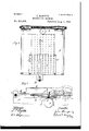
- Figure 1 of the drawings represents a side elevation of the Hall type-writer, so called showing the keyboard in section.
- Fig. 2 represents a reduced plan of the same, showing the position of the index plate for multiplication.
- Fig. 3 represents an arrangement of figures on the types.
- Fig. 4 represents another arrangement of figures on the same.
- Fig. 5 represents the index multiplication plate.
- Fig. 6 represents a bottom View of the type holder or form and its operating mechanism.
- Figs. 7 and 8 represent side elevations of the type mechanism with the type in position for printing, Fig. 7 showing the normal position of the type holder and mechanism and Fig. 8 the position of the parts when a letter or numeral is being printed upon the paper.
- Fig. 9 represents a full sized plan of the index plate for multiplying in position.
- the index plate would have to be connected with the types in such a way that on pointing and printing the result of either figure 9 in the eighth row or 8 in the ninth row, 72 would be printed; and on pointing and printing the result of either figure 9 in the fifth row or 5 in the ninth row 45 would be printed, and so on.
- Suchan arrangement does not appear to he wanted in the case of the Hall type writer, but it might be necessary with other machines, for which it might be advisable to arrange the index plate dif ferently, so that forty-five out of the eightytwo types would bear two indications: for
- one type would represent 8X9 and 9X8; one type 5X9 and 9X5; one type 3X9 and 9X3, and so on.
- A represents the frame of the type-writer and B represents a plate which is hinged at Z) I) and which is capable of lifting up, thereby exposing the paper C upon which the printing is done.
- B represents a plate which is hinged at Z) I) and which is capable of lifting up, thereby exposing the paper C upon which the printing is done.
- This plate B there is a hole cl. This hole is just above and over the periphery of the rubber roll D about which the paper passes.
- the paper C is held in place by the spring-tongue c.
- an elastic type-plate c Just above the ink ribbon but in no wise connected with it is an elastic type-plate c,the same being shown in section, and is held in place by the form t.
- This type-plate is of rubber and ordinarily contains in relief the letters of the alphabet,
- the index plate which contains the letters of the alphabet is shown at h and the index plate for multiplication, that shown by Fig. 5, is shown at At H is shown an arm, hinged at p and connected by means of the plate 7a to the form 0' which latter holds the type plate. .arm H is fastened a pointer h which rests 'on the index platej.
- This index plate j is on a raised form as shown in Fig. 1 and by having it arranged as shown the alphabet index plate h does not have to be removed when it is desired to multiply-but all that need be done is to insert a multiplication type-plate c in the form 11.
- This type plate 0 and holder or form i are is adapted to move intermittently and bring any given letter, or in case of multiplication the product of any two numerals into alignment With the opening (I, and when so brought into alignment the arm II is depressed and the proper letter or figure on the type-plate is pressed, by means of a plunger 9 mounted on plate S through the opening cl upon the paper.
- the spacing mechanism consisting of a worm and gear is shown at p 1.
- the type-holderorform so called,adapted to hold the flexible type-plate upon which, when it is desired to multiply, the plate containing the product of two numerals as shown in Figs. 3 and 4, is fastened, is shown at 1'.
- this type-holder i is fastened by suitable screws t" t" the rubber type-plate 0 containing in relief the figures (the product of two numerals) as shown in Fig. 3 or those as shown in Fig. 4.
- This type-form i is pivoted at 2, 2
- the arms 7, 7 are fastened at 8, S, but so as to permit their free movement however, to the plate S.
- the plunger so called, which is securely fastened to the plate S.
- This plunger g is provided with a collar 8 under which the inner periphery of form 4 moves. It will be seen that by this arrangement of parts the type plate when attached to the form 2'- can be moved by means of the plate 76 and arm H either forward or backward or right and left so that any given product of two numerals can be brought directly over the hole (1 in the plate B and directly under the plunger g, as this plunger g is always directly over and in alignment with the hole d.
- index plate of the multiplier is further shown at j and the index plate of the alphabet is shown at 7t.
- index plates are permanently attached to the top of the plate S.
- index platej are printed or attached in any suitable way the figures, and on the index plate h the letters of the alphabet are printed or fastened as may be desired.
- the index plate h is provided with holes 1; v and the letters are at the bottom of the holes, but so as to be visible when looking from above. Into theseholes a spur t upon the end of the arm H fits when the arm is depressed. This arrangementis desired so that the operator can more easily and quickly have the pointer over the letter it is desired to print.
- the index plate j is not provided with any holes, but the pointer simply rests upon the surface of the index plate.
- the pointer h is made of flexible metal so as to permit the arm H to be easily depressed for the purpose of printing.
- the arm H is adapted to be grasped by the thumb and finger and, as it is hinged at p, can be raised or lowered at the will of the operator and by this construction and arrange ment of parts when the pointer is moved to point a figure that is to be multiplied, the figure or figures representing a portion of the product on the type-form are brought directly under the plunger g and over the hole cl and when the arm H is depressed by the same movement that puts the spur o in the hole, the plunger g presses the given letter or product of the numerals through the hole (1 onto the paper 0, see Fig. 8. After the plate S and its printing mechanism have been depressed as shown in Fig.
- lips or stops which pass loosely through the plate S and are so constructed as to limit the upward movement of the plate S.
Landscapes
- Physics & Mathematics (AREA)
- Engineering & Computer Science (AREA)
- Theoretical Computer Science (AREA)
- Mathematical Physics (AREA)
- Computer Hardware Design (AREA)
- General Physics & Mathematics (AREA)
- Printing Methods (AREA)
Description
(No Model.) -4 Sheets-Sheet 1.
- J. .SAWY'ERf MULTIPLYINGMAOHINE.
N0. 502,425. Patented Aug. 1, 1893..
hulbz Zzkwh'an.
i J. B a J e 1F,
D L Y A.
ATTORNEY. Z
4 Sheets-Sheet a.
(No Model.)
J. SAWYER. MULTIPLYING MACHINE.
No. 502,425. Patented Aug. 1, 1893.
(No Model.) 4 Sheets-Sheet 4.
J SAWYER MULTIPLYING MACHINE.
PatentedlAug. 1, 1893.
. W *7 i y y 9 iimwyoi Zital UNITED STATES PATENT OFFICE.
JOHN SAWYER, OF LONDON, ENGLAND.
MULTIPLYING-MACHINE.
SPECIFICATION forming part of Letters Patent No. 502,425, dated August 1, 1893.
Application filed August 24, 1892. Serial No. 4441018- (No model.)
To all whom it may concern/.-
Be it known that I, JOHN SAWYER, a citizen of Great Britain, residing at London, England, have invented a new and useful lmprovementin lvlultiplyingdvlachines, of which the following is a specification.
This invention relates to improvements in multiplying machines, (or arithmometers,) and it consistsin the adaptation of type-writers of Hall construction to perform the operation of multiplication.
Multiplying machines (or arithmometers) are largely and constantly used in life insurance offices and are very costly besides being liable to get out of order, and the machines heretofore made and noW in use will only multiply numbers consisting of eight places, whereas there is no limit to the number of figures which could be multiplied by my improved multiplier and any multiplication problem and result could be printed off more quickly than the figures can be written down,
all mental labor being saved except the simple process of addition, as hereinafter explained. Although the ordinary arithmometer displays the answer without addition,there is more manipulation required than in my improved machine.
As is well known all type-writers of the Hall class are provided with index plate, operting pointer and type plate by means of which the characters are printed upon the sheet. The index plate of the Halltype-writer, so called, (patent dated March 1, 1881, by Thomas Hall and numbered 238,387, and patent to John R. Robinson, dated March 3, 1891, No. 447,857, type -writers,) happens to be peculiarly well suited to the purposes of my improved multiplier, although other type-writing machines can be changed and adapted to perform the operation of multiplying.
Figure 1 of the drawings represents a side elevation of the Hall type-writer, so called showing the keyboard in section. Fig. 2 represents a reduced plan of the same, showing the position of the index plate for multiplication. Fig. 3 represents an arrangement of figures on the types. Fig. 4: represents another arrangement of figures on the same. Fig. 5 represents the index multiplication plate. Fig. 6 represents a bottom View of the type holder or form and its operating mechanism. Figs. 7 and 8 represent side elevations of the type mechanism with the type in position for printing, Fig. 7 showing the normal position of the type holder and mechanism and Fig. 8 the position of the parts when a letter or numeral is being printed upon the paper. Fig. 9 represents a full sized plan of the index plate for multiplying in position.
For the purpose of my invention I cause the depression of the type plate of the ordinary type-writer to print in some instances two characters instead of only one as is usually the practice when printing letters or numbers, these two characters being numbers representing the product of two numerals. I employ eighty-two figures, eighty-one of them arranged in nine rows of nine each with a single figure to represent zero. The arrangement of the nine rows on the index plate is as follows as also shown in Fig. 5 of the drawings:
rowrowl row-1 I First Second T h i r d Fourth rowl F i f t h row-1 S ix t h rowl Seventh row-1 Eighth rowl Ninth r0w T e n t h row- The figures printed by type plate are respectively:
1 2 3 4 5 6 7 8 9 2 4: (i 810121al618 3 6 9121518212427 4 812162024283236 51015202530354045 61218243036424854 71421283542495663 81624324048566472 As an example in order to multiply eight hundred and fifty-three by nine the figures 8, 5, and 3 in the ninth row will be touched in order thereby printing 72 45 27. If the figures were placed on the types as shown above it would be necessary also to place thereon a perpendicular line in the center as and eight hundred and fifty-three multiplied by nine would appear thus:
so that the figures could be added up in the usual Way.
The multiplication of eight thousand seven hundred and nine by nine thousand eight hundred and sixin the two forms of type will serve as examples.
It is not necessary to have in the typeholder as many as eighty-two types, as some of them are repetitions and the following thirty-seven types are all that need be used in the printing, if found desirable:
For example:
If thirty-seven types only were in the machine, the index plate would have to be connected with the types in such a way that on pointing and printing the result of either figure 9 in the eighth row or 8 in the ninth row, 72 would be printed; and on pointing and printing the result of either figure 9 in the fifth row or 5 in the ninth row 45 would be printed, and so on. Suchan arrangement does not appear to he wanted in the case of the Hall type writer, but it might be necessary with other machines, for which it might be advisable to arrange the index plate dif ferently, so that forty-five out of the eightytwo types would bear two indications: for
example one type would represent 8X9 and 9X8; one type 5X9 and 9X5; one type 3X9 and 9X3, and so on.
The positions of the type-forms and index plate are fully shown in Figs. 1 and 2 of the drawings.
A represents the frame of the type-writer and B represents a plate which is hinged at Z) I) and which is capable of lifting up, thereby exposing the paper C upon which the printing is done. Through this plate B there is a hole cl. This hole is just above and over the periphery of the rubber roll D about which the paper passes. The paper C is held in place by the spring-tongue c. On this plate Bis pasted a thin ink ribbon at of the size of the type plate, so that every time the type plate is depressed as hereinafter explained it inks itself upon the ribbon. Just above the ink ribbon but in no wise connected with it is an elastic type-plate c,the same being shown in section, and is held in place by the form t. This type-plate is of rubber and ordinarily contains in relief the letters of the alphabet, but when it is desired to multiply the typeplate will contain the figures as shown in Fig.3 or those as shown in Fig. 4 of the drawings.
The index plate which contains the letters of the alphabet is shown at h and the index plate for multiplication, that shown by Fig. 5, is shown at At H is shown an arm, hinged at p and connected by means of the plate 7a to the form 0' which latter holds the type plate. .arm H is fastened a pointer h which rests 'on the index platej.
To this This index plate j is on a raised form as shown in Fig. 1 and by having it arranged as shown the alphabet index plate h does not have to be removed when it is desired to multiply-but all that need be done is to insert a multiplication type-plate c in the form 11. This type plate 0 and holder or form i are is adapted to move intermittently and bring any given letter, or in case of multiplication the product of any two numerals into alignment With the opening (I, and when so brought into alignment the arm II is depressed and the proper letter or figure on the type-plate is pressed, by means of a plunger 9 mounted on plate S through the opening cl upon the paper.
The spacing mechanism consisting of a worm and gear is shown at p 1.
The type-holderorform, so called,adapted to hold the flexible type-plate upon which, when it is desired to multiply, the plate containing the product of two numerals as shown in Figs. 3 and 4, is fastened, is shown at 1'. Upon this type-holder i is fastened by suitable screws t" t" the rubber type-plate 0 containing in relief the figures (the product of two numerals) as shown in Fig. 3 or those as shown in Fig. 4.
This rubber type plate is not shown in Fig. 6
of the drawings in order that the mechanism of the type-form can be more clearly explained. This type-form i is pivoted at 2, 2
to arms 3, 3, which, in turn are pivoted at 5, 5 to a frame 4 and this frame 4 is again pivoted at 6, 6 to arms 7, 7. The arms 7, 7 are fastened at 8, S, but so as to permit their free movement however, to the plate S.
At g is shown the plunger, so called, which is securely fastened to the plate S. This plunger g is provided with a collar 8 under which the inner periphery of form 4 moves. It will be seen that by this arrangement of parts the type plate when attached to the form 2'- can be moved by means of the plate 76 and arm H either forward or backward or right and left so that any given product of two numerals can be brought directly over the hole (1 in the plate B and directly under the plunger g, as this plunger g is always directly over and in alignment with the hole d.
In Fig. 9, the index plate of the multiplier is further shown at j and the index plate of the alphabet is shown at 7t. These index plates are permanently attached to the top of the plate S. On this index platej are printed or attached in any suitable way the figures, and on the index plate h the letters of the alphabet are printed or fastened as may be desired.
The index plate h is provided with holes 1; v and the letters are at the bottom of the holes, but so as to be visible when looking from above. Into theseholes a spur t upon the end of the arm H fits when the arm is depressed. This arrangementis desired so that the operator can more easily and quickly have the pointer over the letter it is desired to print.
The index plate j is not provided with any holes, but the pointer simply rests upon the surface of the index plate. The pointer h is made of flexible metal so as to permit the arm H to be easily depressed for the purpose of printing.
The arm H is adapted to be grasped by the thumb and finger and, as it is hinged at p, can be raised or lowered at the will of the operator and by this construction and arrange ment of parts when the pointer is moved to point a figure that is to be multiplied, the figure or figures representing a portion of the product on the type-form are brought directly under the plunger g and over the hole cl and when the arm H is depressed by the same movement that puts the spur o in the hole, the plunger g presses the given letter or product of the numerals through the hole (1 onto the paper 0, see Fig. 8. After the plate S and its printing mechanism have been depressed as shown in Fig. 8 and the hand of the operator lifted the plate and its mechanism immediately fly back to their normal positions as shown in Fig. 7, by the aid of a spring 12 and arms 13, 13 attached to the rod 14, see Fig. 6, the arms 13,13 being all the time pressed downward by the spring.
At 15, 15, are shown lips or stops which pass loosely through the plate S and are so constructed as to limit the upward movement of the plate S.
hen it is desired to multiply my improved type-plate containing the product of the numerals is fastened to the form i (instead and in place of the alphabet plate) and the index plate and pointer being already and always in position and readiness, the same operation is gone through with as in the case of print- The operator if he wishes to multiply three times four puts the pointer h on figure 4: in the third row and depresses the arm H, and the result is that the product, namely twelve, is printed on the paper.
I claim In a multiplying machine the combination with a typewriter of an index plate 'a type plate having type which print characters representing the product of numerals multiplied together and a pointer mounted over said index plate and connected to said type plate to actuate the latter substantially as set forth.
JOHN SAlVYER.
Witnesses:
WILLIAM HowIE, JOHN STEGGALL SAWYER.
Publications (1)
| Publication Number | Publication Date |
|---|---|
| US502425A true US502425A (en) | 1893-08-01 |
Family
ID=2571262
Family Applications (1)
| Application Number | Title | Priority Date | Filing Date |
|---|---|---|---|
| US502425D Expired - Lifetime US502425A (en) | sawyer |
Country Status (1)
| Country | Link |
|---|---|
| US (1) | US502425A (en) |
-
0
- US US502425D patent/US502425A/en not_active Expired - Lifetime
Similar Documents
| Publication | Publication Date | Title |
|---|---|---|
| US502425A (en) | sawyer | |
| US2165223A (en) | Power-operated typewriter | |
| US2848088A (en) | Machine for printing and checking mutually similar records | |
| US2858923A (en) | Typewriting and like machines | |
| US1247585A (en) | Type-writing machine. | |
| US553909A (en) | Machine | |
| US1293739A (en) | Stenographic writing-machine. | |
| US964340A (en) | Type-writer keyboard. | |
| US1673724A (en) | Keyboard attachment for typing and computing machines | |
| US647853A (en) | Pocket type-writer. | |
| US1152494A (en) | Type-writer. | |
| US703689A (en) | Type-writer. | |
| US1181957A (en) | Automatic type-writer operator. | |
| US674967A (en) | Type-writing machine. | |
| US708570A (en) | Printing-machine. | |
| US666411A (en) | Type-writing machine. | |
| US421536A (en) | Type-writing machine | |
| US435349A (en) | Type-writing machine | |
| US1578650A (en) | Typewriting machine | |
| US576948A (en) | Type-writer attachment | |
| US1542222A (en) | Rapid type printer | |
| US709477A (en) | Adding-machine. | |
| US478109A (en) | ingersoll | |
| US1141525A (en) | Stencil-writing attachment for type-writing machines. | |
| US1802921A (en) | Writing machine |