US5023959A - Extendable waste hose system - Google Patents
Extendable waste hose system Download PDFInfo
- Publication number
- US5023959A US5023959A US07/331,965 US33196589A US5023959A US 5023959 A US5023959 A US 5023959A US 33196589 A US33196589 A US 33196589A US 5023959 A US5023959 A US 5023959A
- Authority
- US
- United States
- Prior art keywords
- hose
- waste
- inlet
- structure according
- collar
- Prior art date
- Legal status (The legal status is an assumption and is not a legal conclusion. Google has not performed a legal analysis and makes no representation as to the accuracy of the status listed.)
- Expired - Lifetime
Links
Images


Classifications
-
- E—FIXED CONSTRUCTIONS
- E03—WATER SUPPLY; SEWERAGE
- E03F—SEWERS; CESSPOOLS
- E03F1/00—Methods, systems, or installations for draining-off sewage or storm water
- E03F1/008—Temporary fluid connections for emptying mobile sewage holding tanks, e.g. of trailers, boats
-
- B—PERFORMING OPERATIONS; TRANSPORTING
- B60—VEHICLES IN GENERAL
- B60R—VEHICLES, VEHICLE FITTINGS, OR VEHICLE PARTS, NOT OTHERWISE PROVIDED FOR
- B60R15/00—Arrangements or adaptations of sanitation devices
-
- E—FIXED CONSTRUCTIONS
- E03—WATER SUPPLY; SEWERAGE
- E03F—SEWERS; CESSPOOLS
- E03F1/00—Methods, systems, or installations for draining-off sewage or storm water
-
- F—MECHANICAL ENGINEERING; LIGHTING; HEATING; WEAPONS; BLASTING
- F16—ENGINEERING ELEMENTS AND UNITS; GENERAL MEASURES FOR PRODUCING AND MAINTAINING EFFECTIVE FUNCTIONING OF MACHINES OR INSTALLATIONS; THERMAL INSULATION IN GENERAL
- F16L—PIPES; JOINTS OR FITTINGS FOR PIPES; SUPPORTS FOR PIPES, CABLES OR PROTECTIVE TUBING; MEANS FOR THERMAL INSULATION IN GENERAL
- F16L3/00—Supports for pipes, cables or protective tubing, e.g. hangers, holders, clamps, cleats, clips, brackets
- F16L3/003—Supports for pipes, cables or protective tubing, e.g. hangers, holders, clamps, cleats, clips, brackets devices for holding the open end of a hose
-
- Y—GENERAL TAGGING OF NEW TECHNOLOGICAL DEVELOPMENTS; GENERAL TAGGING OF CROSS-SECTIONAL TECHNOLOGIES SPANNING OVER SEVERAL SECTIONS OF THE IPC; TECHNICAL SUBJECTS COVERED BY FORMER USPC CROSS-REFERENCE ART COLLECTIONS [XRACs] AND DIGESTS
- Y10—TECHNICAL SUBJECTS COVERED BY FORMER USPC
- Y10T—TECHNICAL SUBJECTS COVERED BY FORMER US CLASSIFICATION
- Y10T137/00—Fluid handling
- Y10T137/6851—With casing, support, protector or static constructional installations
- Y10T137/6855—Vehicle
-
- Y—GENERAL TAGGING OF NEW TECHNOLOGICAL DEVELOPMENTS; GENERAL TAGGING OF CROSS-SECTIONAL TECHNOLOGIES SPANNING OVER SEVERAL SECTIONS OF THE IPC; TECHNICAL SUBJECTS COVERED BY FORMER USPC CROSS-REFERENCE ART COLLECTIONS [XRACs] AND DIGESTS
- Y10—TECHNICAL SUBJECTS COVERED BY FORMER USPC
- Y10T—TECHNICAL SUBJECTS COVERED BY FORMER US CLASSIFICATION
- Y10T137/00—Fluid handling
- Y10T137/6851—With casing, support, protector or static constructional installations
- Y10T137/6918—With hose storage or retrieval means
- Y10T137/6932—With retrieval means
Definitions
- RV recreational vehicle
- a loose hose which connects to an outlet on the recreational vehicle by hand, with the other end being manually connected to the inlet of the dump station.
- a fitting must be put on the outboard end of the hose so it adapts to the particular size of the inlet at that particular dump station. Inlets vary from 3" to 41/2", so that the RV operator generally carries three adapters for the three commonly used sizes within that range. This system is the most labor intensive, the messiest, and the most old-fashioned.
- the instant invention fulfills all the above stated needs and goals.
- an accordion hose driver operated by either an electric motor or a crank, for extending the hose out to the appropriate length, or winding it back into its collapsed storage mode inside a cylindrical housing on the RV.
- This driver utilizes a collar around the hose, the interior surface of the collar being configured to engage the helical ribs of the accordion hose so that as the collar rotates in one direction or the other, the hose will extend or retract, respectively.
- the system also includes means for tensioning the hose once it is extended with the outer end engaged in the dump station inlet, so that the tension holds the hose at the desired degree of inclination, with no sagging, without the need of any further hose support equipment.
- the terminal end of the hose is permanently fitted with an elbow-defining structure which will create a 90 degree bend in the end of the hose for convenient fitting in the waste station inlet a universal coupling for fitting inside the inlet of the waste station and adapted to accommodate any of the commonly used inlet sizes eliminates the need to carry multiple adapters, and also enables the fitting to become a permanent fixture at the end of the hose.
- FIG. 1 is the diagrammatic view of the system in use, connected between an RV and a waste dump inlet;
- FIG. 2 is a more detailed view of the hose drive system and the elbow-defining and coupling structures at the outer end of the hose;
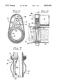
- FIG. 3 is a side elevation view of one type of elbow-defining structure
- FIG. 4 is a side elevation view of another type of elbow-defining structure
- FIG. 5 is a section taken along line 5--5 of FIG. 6;
- FIG. 6 is a side elevation view of the motor driven version of the hose driver showing the accordion hose in phantom;
- FIG. 7 is a side elevation view, partially cut away, of the inlet coupling
- FIG. 8 is a side elevation view, partially cut away, of the hose drive mechanism utilizing a crank rather than an electric motor;
- FIG. 9 is an elevation view of the unidirectional hose cuff
- FIG. 10 is a section taken along line 10--10 of FIG. 9 illustrating the structure that makes the hose tensioner unidirectional;
- FIG. 11 is detail of one section of the hose tensioner illustrating the mechanism by which the hose becomes more greatly tensioned when pulled in one direction than the other;
- FIG. 12 is a side elevation view of an elbow that can replace the end fitting on the hose or fit between the RV outlet and the hose.
- An RV is diagrammatically illustrated at 10 in its parked position while the waste hose 12 is extended from the RV, where it connects internally to the holding tank, to the inlet 14 of an underground waste dump reservoir, not shown.
- the outer end of the hose terminates in a coupling 16 and an elbow 18 which can be provided in one of several forms all of which have the capability converting from the substantially 90 degree bend as shown to a generally linear extension to enable it to fit better in its compartment inside the recreational vehicle.
- the hose driver 18 This driver works on a principle that is sometimes used to axially displace threaded shafts, wherein an external collar 20 engages around the accordion hose, which has a continuous helical rib 22.
- the inner surface 24 of the collar defines a wide helical groove 26 between the collar's spaced ribs 28, with the ribs in the groove being mated as indicated in FIG. 6 so that rotation of the collar will move the accordion hose to the left or to the right.
- the external surface of the collar 20 defines spaced teeth 30 around its circumference which are engaged by the toothed belt 32, driven by the gear 34 of electric motor 36.
- a belt housing 38 is used for the conventional reasons.
- FIG. 8 An alternative to the electric motor 36 is a hand-driven crank version illustrated in FIG. 8.
- a drive shaft 40 extends from the side 42 of the RV into the belt housing 38, where it engages the belt 32 substantially as does the electric motor in the previous embodiment.
- the outer end of the drive shaft is fitted with a quad- or a hex-socket nut 44 which is engaged by the mating end 46 of the hand crank 48.
- the crank handle is of course removed when not in use and stowed in the vehicle.
- other arrangements could be used, such as one in which the crank is collapsible against the outside or inside of the RV.
- the collar 20 does not ride on roller or ball bearings, but simply slides in its track, being centered by the shoulders it defines at 50.
- the collar and the bearing surfaces of the belt housing in which the collar rotates must have a low-friction interface.
- the collar could be made of nylon or another low-friction material.
- the hose When the hose is collapsed as indicated in the right side of FIG. 6, it is stowed within a collapsed hose housing 52, and the inner end of the hose is permanently connected to the outlet of the waste holding tank of the recreational vehicle, which is not shown.
- the entire mechanism, including the housing 52, is mounted to a framework attached to the superstructure of the vehicle, with the details of the framework and its connection to the vehicle depending on the make and model of the RV to which the mechanism is mounted.
- a mechanical elbow is required just above the dump station inlet.
- a rigid elbow could be used, but it is one of the goals of the instant invention to permit the end of the hose to straighten out for stowage, so that it will fit conveniently inside the coupling housing 54, shown in FIGS. 2 and 6, and permit the door 56, shown in FIG. 2, to close to define a substantially flush outer surface for the wall of the RV.
- FIG. 2 which is the preferred embodiment, a pair of spaced ferrules 58 are mounted to the exterior surface of the hose as shown.
- the ferrules could be bonded to the hose, but would more likely be provided with the same type of interior grooving as the collar 20, and just rotated on to the end of the hose before the coupling is installed.
- each ferrule At one edge of each ferrule is an eyelet 60, and one of the eyelets mounts a hook 62.
- the other eyelet serves as a point of engagement for the end of the hook.
- a rotary joint 64 which comprises a pair of annular flanges 66 held firmly together by a retainer ring 68.
- the phantom lines in FIG. 3 illustrate the position taken by the mechanism when straightened, which is not entirely straight, but rather defines a slight S-curve.
- FIG. 4 illustrates a typical stovepipe bend system in which telescoping pipe segments 70 can be moved to define any desired angle, including straight, as shown in phantom in that figure.
- the hose drive 18 is reversed, winding the inner end of the hose back into the housing 52, thereby tensioning the hose until it substantially straightens, eliminating the central dip.
- Hose strength of currently used hoses is more than adequate to sustain the require tension, and the coupling also is sufficiently strong, and engages in the inlet with sufficient friction to prevent its breaking or popping free of the inlet while the hose is being tensioned.
- the difference in diameter between the cylindrical nozzle 76, ring 74 and gasket 72 is such that the nozzle will fit inside the smallest diameter inlet, ordinarily 3", and the gasket is wide enough to seal against inlets up to 41/2" wide, ordinarily the widest inlet in use at dump stations.
- this means comes in the form of a series of spaced, longitudinally extended spring fingers 78.
- These spring elements are connected at the bottom with a ring 80, of which they are apart, and extend up inside the gasket, where they are permitted to slide up and down to accommodate the compression of the fingers by the sides of the inlet 16.
- This frictional mechanism permits a pressed fit of the coupling into any inlet, resulting in there being adequate friction between the spring fingers and the sides of the inlets to hold the gasket 72 firmly down against the top of the inlet.
- the unidirectional hose tensioner 82 illustrated in FIGS. 9-11.
- the unidirectional hose tensioner could be used to replace the drive mechanism 18, or it could be used by the drive mechanism as the collar 20, will the advantages described below.
- the hose tensioner is simple in construction, comprising of a flexible, planar annular ring 84 which is preferably divided by V-cuts 86 into a series of angularly spaced segments 88.
- the periphery of the ring 84 is continuous and is not broken by the V-cuts.
- the periphery is sandwiched between two rigid support rings, an outer support ring 90 and an inner support ring 92 of larger internal diameter than the outer ring 90. These rings are compressed in a suitable housing 94.
- the whole purpose of the hose tensioner is accomplished by the differing internal diameters of the support rings 90 and 92. Because the outer ring 90 is smaller in internal diameter, it supports the ring 84 to a much greater extent than does the ring 92, so that when the hose is pulled outward, or to the left in FIG. 10, it encounters much greater resistance from the ring 84 than when the hose is pushed back into the vehicle or to the right in FIG. 10.
- the tensioner when used as the collar 20, the hose ribs would pass through the V-cuts 86 without any problem.
- the tensioner When the tensioner is rotated by the hose drive mechanism, it would axially drive the hose in or out, just as does the collar 20. Additionally however, the hose can be pulled out when the hose drive is de-energized, if enough tension is put on the hose. When it is desired to push the hose back into its housing 52 however, much less resistance is provided by the tensioner.
- the tensioner as the collar has at least two advantages.
- the second advantage is that even if the hose drive is working, it might take 60 seconds or so for the electric motor, or the crank, to drive the hose back into its housing 52, whereas it could simply be pushed in by the operator in a much shorter period of time.
- FIG. 12 Another optional component of the invention is the elbow 96, illustrated in FIG. 12.
- This elbow has a rigid stub pipe 98 and an end pipe 100 which slides axially along the stub pipe.
- the end pipe has a side outlet 102 which communicates freely with the stub pipe 98 when the pipe is pulled out into its open position shown in phantom in FIG. 12, but is closed off when the stub pipe is pushed in and locked with the hook-and-peg latches 104.
- Other latching means could be provided to lock the end cap in the extended mode shown in phantom.
- the elbow 96 can be used in two possible places: either at the upstream end of the hose, connecting the hose to the RV, or as the elbow bend and cap at the end of the hose that connects to the RV waste system.
- the unit When used at the upstream end, the unit accommodates a code requirement that the RV waste system terminate in a rigid coupling rather than a hose.
- another coupling/adaptor When used at the downstream end of the hose, another coupling/adaptor would be required to adapt the outlet 102 to the dump station inlet.
- waste dumping is the problem to which many have directed their attention.
- their attention has ordinarily been directed to component problems of the entire operation, rather than defining a different operation that substantially eliminates the component problems.
- one patent might illustrate a system for storing the collapsed waste hose conveniently underneath the recreational vehicle, while another patent might disclose an apparatus for supporting the hose along its length to define the required incline.
- different coupling are provided.
- what is needed, and what this invention provides is a comprehensive system which attacks all of the problems incidental to waste dumping from a recreational vehicle, and minimizes the aggravation and waste spillage, while maximizing speed, efficiency, and convenience of the operation.
Abstract
Description
Claims (17)
Priority Applications (3)
| Application Number | Priority Date | Filing Date | Title |
|---|---|---|---|
| US07/331,965 US5023959A (en) | 1989-04-03 | 1989-04-03 | Extendable waste hose system |
| AU65871/90A AU620778B1 (en) | 1989-04-03 | 1990-11-07 | Extendable waste hose system |
| AU65871/90D AU6587190A (en) | 1989-04-03 | 1990-11-07 | Extendable waste hose system |
Applications Claiming Priority (1)
| Application Number | Priority Date | Filing Date | Title |
|---|---|---|---|
| US07/331,965 US5023959A (en) | 1989-04-03 | 1989-04-03 | Extendable waste hose system |
Publications (1)
| Publication Number | Publication Date |
|---|---|
| US5023959A true US5023959A (en) | 1991-06-18 |
Family
ID=23296113
Family Applications (1)
| Application Number | Title | Priority Date | Filing Date |
|---|---|---|---|
| US07/331,965 Expired - Lifetime US5023959A (en) | 1989-04-03 | 1989-04-03 | Extendable waste hose system |
Country Status (2)
| Country | Link |
|---|---|
| US (1) | US5023959A (en) |
| AU (2) | AU6587190A (en) |
Cited By (58)
| Publication number | Priority date | Publication date | Assignee | Title |
|---|---|---|---|---|
| US5226456A (en) * | 1991-12-09 | 1993-07-13 | Semak Mark A | Support for length of flexible or light gauge hose or piping |
| US5247974A (en) * | 1992-01-21 | 1993-09-28 | Thetford Corporation | Pneumatic sealing device for waste disposal systems |
| US5294518A (en) * | 1992-05-01 | 1994-03-15 | International Business Machines Corporation | Amorphous write-read optical storage memory |
| US5311753A (en) * | 1991-06-19 | 1994-05-17 | Shiro Kanao | Drain hose for washing machine and which includes a corrugated intermediate portion |
| US5311909A (en) * | 1992-10-19 | 1994-05-17 | Adcock John R | Flexible hose stabilizing device |
| US5330233A (en) * | 1993-04-27 | 1994-07-19 | James Kress | Recreational vehicle sewer apparatus |
| US5897083A (en) * | 1998-01-12 | 1999-04-27 | Johnson; Albert P. | Retainer for recreational vehicle sewer hose |
| US5904183A (en) * | 1996-10-15 | 1999-05-18 | Leech; Alan R. | Recreational vehicle waste drainer |
| US5947156A (en) * | 1997-03-11 | 1999-09-07 | Tomczyk; Frederick A. | Holding tank having waste evacuation device |
| US5988221A (en) * | 1998-02-23 | 1999-11-23 | Walker; Dewey W. | Drain line extender for recreational vehicles |
| US6223767B1 (en) | 2000-04-01 | 2001-05-01 | William Blake Otis | Stowage receptacle for a recreational vehicle waste hose |
| US6371148B1 (en) * | 1999-03-31 | 2002-04-16 | Certainteed Corporation | Hose feed and retrieval system related applications |
| US6516836B2 (en) * | 2000-12-22 | 2003-02-11 | Reginald E Fields | Motorized waste hose for recreational vehicle |
| US6543484B1 (en) * | 2000-08-15 | 2003-04-08 | Roderick Highsmith | Waste water disposal system |
| US6607009B2 (en) * | 2001-06-13 | 2003-08-19 | Marathon Coach, Inc. | Sewage system for vehicles |
| US20030183413A1 (en) * | 2002-03-27 | 2003-10-02 | Yazaki Corporation | Harness fixing device |
| US20040063395A1 (en) * | 2001-03-05 | 2004-04-01 | Bombardi Harry G. | Device and a method for supplying conditioned air to an aircraft |
| US20040084098A1 (en) * | 2002-10-29 | 2004-05-06 | Phase Four Industries, Inc. | Waste evacuation system for a vehicle |
| WO2004039638A2 (en) * | 2002-10-29 | 2004-05-13 | Phase Four Industries, Inc. | Method and apparatus for waste evacuation |
| US6746178B1 (en) * | 2001-08-13 | 2004-06-08 | Gerald M. Hensley | Sewer drain receptacle with hose resting seat |
| US20040121718A1 (en) * | 2002-12-21 | 2004-06-24 | Grochowski Gary L. | Air delivery unit, hose and deploying device therefor |
| US20050150562A1 (en) * | 2004-01-12 | 2005-07-14 | Anderson Ronald B. | Sewage dump system for RV, marine and other mobile vehicles |
| US6948527B2 (en) | 2001-11-24 | 2005-09-27 | Gary Dean Ragner | Pressure-actuated linearly retractable and extendible hose |
| US6983757B1 (en) * | 1999-10-13 | 2006-01-10 | Ascent Systems, Inc. | Pressure differential distribution system |
| US20060070660A1 (en) * | 2003-10-24 | 2006-04-06 | Phase Four Industries, Inc. | Waste evacuation system for a vehicle |
| US20080084032A1 (en) * | 2006-10-10 | 2008-04-10 | Cravens Jerry R | Pest control seal for recreational vehicle |
| US20090032652A1 (en) * | 2007-07-19 | 2009-02-05 | Anatoly Gosis | System for moving and storing a conduit for supplying air to an aircraft |
| US20090197516A1 (en) * | 2008-02-02 | 2009-08-06 | Wright Joe W | Hose Management System for Supplying Conditioned Air to an Aircraft |
| US20090277830A1 (en) * | 2008-05-02 | 2009-11-12 | Eastwood Research, Inc. | Septage treatment system and method of treating septage |
| US20100206336A1 (en) * | 2009-02-18 | 2010-08-19 | Sami Souid | Extendable vacuum cleaner |
| WO2011064808A1 (en) | 2009-11-26 | 2011-06-03 | Enio Stazi | Machine for extending and retracting a corrugated pipe |
| US20110132485A1 (en) * | 2009-11-30 | 2011-06-09 | Norco Industries, Inc. | Termination valve extension |
| USRE42688E1 (en) | 2000-10-17 | 2011-09-13 | Thetford Corporation | Vehicle wastewater drainage system |
| US8291942B2 (en) | 2011-11-04 | 2012-10-23 | Blue Gentian, Llc | Expandable hose assembly |
| US8291941B1 (en) | 2011-11-04 | 2012-10-23 | Blue Gentian, Llc | Expandable and contractible hose |
| US8459296B2 (en) | 2010-08-20 | 2013-06-11 | Illinois Tool Works | Aircraft hose retrieval system |
| US8479776B2 (en) | 2011-11-04 | 2013-07-09 | Blue Gentian, Llc | Expandable garden hose |
| US8544894B1 (en) * | 2011-12-16 | 2013-10-01 | David M. Borba | Recreational vehicle waste hose coupling assembly |
| US20130281003A1 (en) * | 2012-04-18 | 2013-10-24 | Douglas A. Newcomer | Extendable vent system |
| US8757213B2 (en) | 2011-11-04 | 2014-06-24 | Blue Gentian, Llc | Commercial hose |
| US8776836B2 (en) | 2001-11-24 | 2014-07-15 | Ragner Technology Corporation | Linearly retractable pressure hose structure |
| US8936046B2 (en) | 2012-11-09 | 2015-01-20 | Ragner Technology Corporation | Elastic and spring biased retractable hoses |
| US20150041016A1 (en) * | 2013-08-10 | 2015-02-12 | Ragner Technology Corporation | Retractable elastic bungee hose |
| US20150067978A1 (en) * | 2013-09-12 | 2015-03-12 | Shop Vac Corporation | Drain system and method for vacuum cleaner |
| US9127791B2 (en) | 2012-11-09 | 2015-09-08 | Ragner Technology Corporation | Lubricated elastically biased stretch hoses |
| USD748763S1 (en) | 2014-11-05 | 2016-02-02 | Blue Gentian, Llc | Expandable hose inlet coupler |
| USD748764S1 (en) | 2014-11-05 | 2016-02-02 | Blue Gentian, Llc | Expandable hose outlet coupler |
| US9303409B2 (en) * | 2014-03-25 | 2016-04-05 | Luis F. Lopez | Cleanout boom |
| US20170050619A1 (en) * | 2015-08-21 | 2017-02-23 | Randy Greene | Recreational vehicle service compartment sealing shroud |
| US20170303760A1 (en) * | 2013-03-01 | 2017-10-26 | Omachron Intellectual Property Inc. | Surface cleaning apparatus |
| US9844921B2 (en) | 2013-08-10 | 2017-12-19 | Ragner Technology Corporation | Annular-pleated circular braid |
| US10174870B2 (en) | 2011-11-04 | 2019-01-08 | Telebrands Corp. | Expandable and contractible garden hose |
| US10359131B2 (en) | 2012-12-01 | 2019-07-23 | Ragner Technology Corporation | Collapsible hoses and pressure systems |
| US20200071922A1 (en) * | 2018-08-30 | 2020-03-05 | Jonathan Calvin | Waste disposal docking system for recreational vehicles and method of use |
| USRE47927E1 (en) | 2013-08-10 | 2020-04-07 | Ragner Technology Corporation | Annular-pleated circular braid |
| US20210078509A1 (en) * | 2018-05-01 | 2021-03-18 | Thetford Bv | Discharge device for vehicle wastewater management system |
| US11022246B1 (en) | 2020-06-02 | 2021-06-01 | Bradley L. Bernosky | Waste system securing strap assembly |
| US11927284B2 (en) | 2020-06-24 | 2024-03-12 | Winston Products Llc | Expandable hose |
Citations (25)
| Publication number | Priority date | Publication date | Assignee | Title |
|---|---|---|---|---|
| US2282600A (en) * | 1938-08-12 | 1942-05-12 | Samuel O Blanc | Machine for cleaning large drain tile and the like |
| US2346728A (en) * | 1941-10-20 | 1944-04-18 | Carlson Emil | Power driven operating means for extensible and retractable aerials |
| US2490736A (en) * | 1949-12-06 | Apparatus for watering | ||
| US2511391A (en) * | 1947-12-05 | 1950-06-13 | Dayton Pump & Mfg Co | Extensible gasoline dispensing hose and associated mechanism |
| US2872246A (en) * | 1957-04-04 | 1959-02-03 | Frank P Zierden | Hose reel mounting |
| US3712331A (en) * | 1971-03-03 | 1973-01-23 | C Otto | Holding tank evacuating apparatus for a recreational vehicle |
| US3730228A (en) * | 1972-01-05 | 1973-05-01 | P Gibbs | Hose-case assembly |
| US3809348A (en) * | 1972-03-14 | 1974-05-07 | E Dilaura | External waste pipe support stand for trailers |
| US3811462A (en) * | 1972-06-08 | 1974-05-21 | J Feliz | Recreational vehicle utility stowage and transfer system |
| US3819137A (en) * | 1972-04-20 | 1974-06-25 | H Smith | Trestle for a flexible hose |
| US3860978A (en) * | 1973-05-18 | 1975-01-21 | Paul H Wirth | Time saving drain assembly for sinks, bathtubs, etc. |
| US3882565A (en) * | 1973-11-30 | 1975-05-13 | Lawrence F Irwin | Spring feed device |
| US3955599A (en) * | 1973-10-01 | 1976-05-11 | Deep Oil Technology, Inc. | Apparatus for bending a flowline under subsea conditions |
| US3958297A (en) * | 1973-04-28 | 1976-05-25 | Kabushiki Kaisha Hukuba Future Research | Suction cleaner |
| US4066093A (en) * | 1975-10-01 | 1978-01-03 | Nitro Nobel Ab | Hose feeding winch |
| US4125237A (en) * | 1977-04-08 | 1978-11-14 | Hagins James H | Waste pipe support |
| US4133347A (en) * | 1977-10-31 | 1979-01-09 | Albert Mercer | Waste evacuation attachment for recreational vehicles |
| US4151864A (en) * | 1975-03-31 | 1979-05-01 | Arundale, Inc. | Drain adapter for corrugated hose |
| US4223702A (en) * | 1978-12-26 | 1980-09-23 | James Cook | Drain line for recreational vehicles |
| US4231595A (en) * | 1978-11-29 | 1980-11-04 | Knutsen Karl I | Waste dispensing device for recreational vehicles and the like |
| US4650224A (en) * | 1985-09-25 | 1987-03-17 | Smith Donald E | Apparatus for discharging sewage from travel trailers and the like |
| US4712755A (en) * | 1986-10-20 | 1987-12-15 | Robbins Daniel T | Hose support |
| US4796926A (en) * | 1986-12-23 | 1989-01-10 | Rapsilver Benny L | Dump fitting for sewer hose |
| US4844121A (en) * | 1988-10-12 | 1989-07-04 | Duke Robert L | RV sewage line assembly |
| US4854349A (en) * | 1987-04-28 | 1989-08-08 | Dennis Foreman | Sewage draining device for recreational vehicles or the like |
-
1989
- 1989-04-03 US US07/331,965 patent/US5023959A/en not_active Expired - Lifetime
-
1990
- 1990-11-07 AU AU65871/90D patent/AU6587190A/en active Granted
- 1990-11-07 AU AU65871/90A patent/AU620778B1/en not_active Ceased
Patent Citations (25)
| Publication number | Priority date | Publication date | Assignee | Title |
|---|---|---|---|---|
| US2490736A (en) * | 1949-12-06 | Apparatus for watering | ||
| US2282600A (en) * | 1938-08-12 | 1942-05-12 | Samuel O Blanc | Machine for cleaning large drain tile and the like |
| US2346728A (en) * | 1941-10-20 | 1944-04-18 | Carlson Emil | Power driven operating means for extensible and retractable aerials |
| US2511391A (en) * | 1947-12-05 | 1950-06-13 | Dayton Pump & Mfg Co | Extensible gasoline dispensing hose and associated mechanism |
| US2872246A (en) * | 1957-04-04 | 1959-02-03 | Frank P Zierden | Hose reel mounting |
| US3712331A (en) * | 1971-03-03 | 1973-01-23 | C Otto | Holding tank evacuating apparatus for a recreational vehicle |
| US3730228A (en) * | 1972-01-05 | 1973-05-01 | P Gibbs | Hose-case assembly |
| US3809348A (en) * | 1972-03-14 | 1974-05-07 | E Dilaura | External waste pipe support stand for trailers |
| US3819137A (en) * | 1972-04-20 | 1974-06-25 | H Smith | Trestle for a flexible hose |
| US3811462A (en) * | 1972-06-08 | 1974-05-21 | J Feliz | Recreational vehicle utility stowage and transfer system |
| US3958297A (en) * | 1973-04-28 | 1976-05-25 | Kabushiki Kaisha Hukuba Future Research | Suction cleaner |
| US3860978A (en) * | 1973-05-18 | 1975-01-21 | Paul H Wirth | Time saving drain assembly for sinks, bathtubs, etc. |
| US3955599A (en) * | 1973-10-01 | 1976-05-11 | Deep Oil Technology, Inc. | Apparatus for bending a flowline under subsea conditions |
| US3882565A (en) * | 1973-11-30 | 1975-05-13 | Lawrence F Irwin | Spring feed device |
| US4151864A (en) * | 1975-03-31 | 1979-05-01 | Arundale, Inc. | Drain adapter for corrugated hose |
| US4066093A (en) * | 1975-10-01 | 1978-01-03 | Nitro Nobel Ab | Hose feeding winch |
| US4125237A (en) * | 1977-04-08 | 1978-11-14 | Hagins James H | Waste pipe support |
| US4133347A (en) * | 1977-10-31 | 1979-01-09 | Albert Mercer | Waste evacuation attachment for recreational vehicles |
| US4231595A (en) * | 1978-11-29 | 1980-11-04 | Knutsen Karl I | Waste dispensing device for recreational vehicles and the like |
| US4223702A (en) * | 1978-12-26 | 1980-09-23 | James Cook | Drain line for recreational vehicles |
| US4650224A (en) * | 1985-09-25 | 1987-03-17 | Smith Donald E | Apparatus for discharging sewage from travel trailers and the like |
| US4712755A (en) * | 1986-10-20 | 1987-12-15 | Robbins Daniel T | Hose support |
| US4796926A (en) * | 1986-12-23 | 1989-01-10 | Rapsilver Benny L | Dump fitting for sewer hose |
| US4854349A (en) * | 1987-04-28 | 1989-08-08 | Dennis Foreman | Sewage draining device for recreational vehicles or the like |
| US4844121A (en) * | 1988-10-12 | 1989-07-04 | Duke Robert L | RV sewage line assembly |
Cited By (105)
| Publication number | Priority date | Publication date | Assignee | Title |
|---|---|---|---|---|
| US5311753A (en) * | 1991-06-19 | 1994-05-17 | Shiro Kanao | Drain hose for washing machine and which includes a corrugated intermediate portion |
| US5226456A (en) * | 1991-12-09 | 1993-07-13 | Semak Mark A | Support for length of flexible or light gauge hose or piping |
| US5247974A (en) * | 1992-01-21 | 1993-09-28 | Thetford Corporation | Pneumatic sealing device for waste disposal systems |
| US5294518A (en) * | 1992-05-01 | 1994-03-15 | International Business Machines Corporation | Amorphous write-read optical storage memory |
| US5311909A (en) * | 1992-10-19 | 1994-05-17 | Adcock John R | Flexible hose stabilizing device |
| US5330233A (en) * | 1993-04-27 | 1994-07-19 | James Kress | Recreational vehicle sewer apparatus |
| US5904183A (en) * | 1996-10-15 | 1999-05-18 | Leech; Alan R. | Recreational vehicle waste drainer |
| US5947156A (en) * | 1997-03-11 | 1999-09-07 | Tomczyk; Frederick A. | Holding tank having waste evacuation device |
| US5897083A (en) * | 1998-01-12 | 1999-04-27 | Johnson; Albert P. | Retainer for recreational vehicle sewer hose |
| US5988221A (en) * | 1998-02-23 | 1999-11-23 | Walker; Dewey W. | Drain line extender for recreational vehicles |
| US6371148B1 (en) * | 1999-03-31 | 2002-04-16 | Certainteed Corporation | Hose feed and retrieval system related applications |
| US6983757B1 (en) * | 1999-10-13 | 2006-01-10 | Ascent Systems, Inc. | Pressure differential distribution system |
| US6223767B1 (en) | 2000-04-01 | 2001-05-01 | William Blake Otis | Stowage receptacle for a recreational vehicle waste hose |
| US6957668B1 (en) * | 2000-08-15 | 2005-10-25 | Roderick Highsmith | Waste water disposal system |
| US6543484B1 (en) * | 2000-08-15 | 2003-04-08 | Roderick Highsmith | Waste water disposal system |
| USRE42688E1 (en) | 2000-10-17 | 2011-09-13 | Thetford Corporation | Vehicle wastewater drainage system |
| US8656963B2 (en) | 2000-10-17 | 2014-02-25 | Thetford Corporation | Vehicle wastewater drainage system |
| US6516836B2 (en) * | 2000-12-22 | 2003-02-11 | Reginald E Fields | Motorized waste hose for recreational vehicle |
| US20040063395A1 (en) * | 2001-03-05 | 2004-04-01 | Bombardi Harry G. | Device and a method for supplying conditioned air to an aircraft |
| US20040209565A1 (en) * | 2001-03-05 | 2004-10-21 | Bombardi Harry G. | Apparatus and a method for supplying conditioned air to an aircraft |
| US6834668B2 (en) * | 2001-03-05 | 2004-12-28 | Boom Air, Llc | Device and a method for supplying conditioned air to an aircraft |
| US20040031528A1 (en) * | 2001-06-13 | 2004-02-19 | Schoellhorn Robert A. | Sewage system for vehicles |
| US7431051B2 (en) * | 2001-06-13 | 2008-10-07 | Marathon Coach, Inc. | Sewage system for vehicles |
| US6607009B2 (en) * | 2001-06-13 | 2003-08-19 | Marathon Coach, Inc. | Sewage system for vehicles |
| US6746178B1 (en) * | 2001-08-13 | 2004-06-08 | Gerald M. Hensley | Sewer drain receptacle with hose resting seat |
| US20060070679A1 (en) * | 2001-11-24 | 2006-04-06 | Ragner Gary D | Linearly retractable pressure hose |
| US20160116087A1 (en) | 2001-11-24 | 2016-04-28 | Ragner Technology Corporation | Multi-layer pressure actuated extendable hose |
| US9371944B2 (en) | 2001-11-24 | 2016-06-21 | Ragner Technology Corporation | Multi-layer pressure actuated extendable hose |
| US6948527B2 (en) | 2001-11-24 | 2005-09-27 | Gary Dean Ragner | Pressure-actuated linearly retractable and extendible hose |
| US10309560B2 (en) | 2001-11-24 | 2019-06-04 | Ragner Technology Corporation | Multi-layer pressure actuated extendable hose |
| US8776836B2 (en) | 2001-11-24 | 2014-07-15 | Ragner Technology Corporation | Linearly retractable pressure hose structure |
| US7549448B2 (en) | 2001-11-24 | 2009-06-23 | Gary Dean Ragner | Linearly retractable pressure hose |
| US9022076B2 (en) | 2001-11-24 | 2015-05-05 | Ragner Technology Corporation | Linearly retractable pressure hose structure |
| US20030183413A1 (en) * | 2002-03-27 | 2003-10-02 | Yazaki Corporation | Harness fixing device |
| US6717055B2 (en) * | 2002-03-27 | 2004-04-06 | Yazaki Corporation | Harness fixing device |
| US20040112432A1 (en) * | 2002-10-29 | 2004-06-17 | Phase Four Industries, Inc. | Method and apparatus for waste evacuation |
| US20070113871A1 (en) * | 2002-10-29 | 2007-05-24 | Phase Four Industries, Inc. | Method and apparatus for waste evacuation |
| US20070113896A1 (en) * | 2002-10-29 | 2007-05-24 | Phase Four Industries, Inc. | Method and apparatus for waste evacuation |
| US20070295420A1 (en) * | 2002-10-29 | 2007-12-27 | Phase Four Industries, Inc. | Method and apparatus for waste evacuation |
| US20070113897A1 (en) * | 2002-10-29 | 2007-05-24 | Phase Four Industries, Inc. | Method and apparatus for waste evacuation |
| US20040084098A1 (en) * | 2002-10-29 | 2004-05-06 | Phase Four Industries, Inc. | Waste evacuation system for a vehicle |
| US20070113898A1 (en) * | 2002-10-29 | 2007-05-24 | Phase Four Industries, Inc. | Method and apparatus for waste evacuation |
| WO2004039638A3 (en) * | 2002-10-29 | 2009-04-23 | Phase Four Ind Inc | Method and apparatus for waste evacuation |
| WO2004039638A2 (en) * | 2002-10-29 | 2004-05-13 | Phase Four Industries, Inc. | Method and apparatus for waste evacuation |
| WO2004039637A3 (en) * | 2002-10-29 | 2004-07-01 | Phase Four Ind Inc | Waste evacuation system for a vehicle |
| US8616241B2 (en) | 2002-10-29 | 2013-12-31 | Douglas R. Swarts | Waste evacuation system for a vehicle |
| US6802769B2 (en) * | 2002-12-21 | 2004-10-12 | Gary L. Grochowski | Air delivery unit, hose and deploying device therefor |
| US20040121718A1 (en) * | 2002-12-21 | 2004-06-24 | Grochowski Gary L. | Air delivery unit, hose and deploying device therefor |
| US20060070660A1 (en) * | 2003-10-24 | 2006-04-06 | Phase Four Industries, Inc. | Waste evacuation system for a vehicle |
| US20050150562A1 (en) * | 2004-01-12 | 2005-07-14 | Anderson Ronald B. | Sewage dump system for RV, marine and other mobile vehicles |
| US20080084032A1 (en) * | 2006-10-10 | 2008-04-10 | Cravens Jerry R | Pest control seal for recreational vehicle |
| US8128132B2 (en) | 2006-10-10 | 2012-03-06 | Rtc Technical Services Inc. | Pest control seal for recreational vehicle |
| US20090032652A1 (en) * | 2007-07-19 | 2009-02-05 | Anatoly Gosis | System for moving and storing a conduit for supplying air to an aircraft |
| US20090197516A1 (en) * | 2008-02-02 | 2009-08-06 | Wright Joe W | Hose Management System for Supplying Conditioned Air to an Aircraft |
| EP2085311A3 (en) * | 2008-02-02 | 2013-05-08 | Twist Inc. | Hose management system for supplying conditioned air to an aircraft |
| US10155595B2 (en) | 2008-02-02 | 2018-12-18 | Twist, Inc. | Hose management system for supplying conditioned air to an aircraft |
| US9365297B2 (en) * | 2008-02-02 | 2016-06-14 | Twist, Inc. | Hose management system for supplying conditioned air to an aircraft |
| EP2727842A1 (en) * | 2008-02-02 | 2014-05-07 | Twist Inc. | Hose management system for supplying conditioned air to an aircraft |
| US20090277830A1 (en) * | 2008-05-02 | 2009-11-12 | Eastwood Research, Inc. | Septage treatment system and method of treating septage |
| US20100206336A1 (en) * | 2009-02-18 | 2010-08-19 | Sami Souid | Extendable vacuum cleaner |
| WO2011064808A1 (en) | 2009-11-26 | 2011-06-03 | Enio Stazi | Machine for extending and retracting a corrugated pipe |
| US8469049B2 (en) * | 2009-11-30 | 2013-06-25 | Norco Industries, Inc. | Termination valve extension |
| US20110132485A1 (en) * | 2009-11-30 | 2011-06-09 | Norco Industries, Inc. | Termination valve extension |
| US8459296B2 (en) | 2010-08-20 | 2013-06-11 | Illinois Tool Works | Aircraft hose retrieval system |
| US8291941B1 (en) | 2011-11-04 | 2012-10-23 | Blue Gentian, Llc | Expandable and contractible hose |
| EP2657585B1 (en) | 2011-11-04 | 2017-11-01 | Blue Gentian, LLC | Expandable hose assembly |
| US8757213B2 (en) | 2011-11-04 | 2014-06-24 | Blue Gentian, Llc | Commercial hose |
| US9841127B2 (en) | 2011-11-04 | 2017-12-12 | Blue Gentian, Llc | Garden hose device and method |
| US10174870B2 (en) | 2011-11-04 | 2019-01-08 | Telebrands Corp. | Expandable and contractible garden hose |
| EP2520840A2 (en) | 2011-11-04 | 2012-11-07 | Blue Gentian, LLC | Expandable hose assembly |
| US9279525B2 (en) | 2011-11-04 | 2016-03-08 | Blue Gentian, Llc | Commercial hose |
| US11608915B2 (en) | 2011-11-04 | 2023-03-21 | Telebrands Corp. | Expandable and contractible garden hose |
| DE202012012762U1 (en) | 2011-11-04 | 2013-10-17 | Blue Gentian, Llc | Extensible hose assembly |
| DE202012012663U1 (en) | 2011-11-04 | 2013-07-30 | Blue Gentian, Llc | Extensible hose assembly |
| US8291942B2 (en) | 2011-11-04 | 2012-10-23 | Blue Gentian, Llc | Expandable hose assembly |
| EP2657585A1 (en) | 2011-11-04 | 2013-10-30 | Blue Gentian, LLC | Expandable hose assembly |
| US10890278B2 (en) | 2011-11-04 | 2021-01-12 | Telebrands Corp. | Expandable and contractible garden hose |
| US8479776B2 (en) | 2011-11-04 | 2013-07-09 | Blue Gentian, Llc | Expandable garden hose |
| US8544894B1 (en) * | 2011-12-16 | 2013-10-01 | David M. Borba | Recreational vehicle waste hose coupling assembly |
| CN104379980A (en) * | 2012-04-18 | 2015-02-25 | X畅尔股份有限公司 | Extendable vent system |
| US20130281003A1 (en) * | 2012-04-18 | 2013-10-24 | Douglas A. Newcomer | Extendable vent system |
| US9127791B2 (en) | 2012-11-09 | 2015-09-08 | Ragner Technology Corporation | Lubricated elastically biased stretch hoses |
| US9982808B2 (en) | 2012-11-09 | 2018-05-29 | Ranger Technology Corporation | Spring biased retractable hoses |
| US8936046B2 (en) | 2012-11-09 | 2015-01-20 | Ragner Technology Corporation | Elastic and spring biased retractable hoses |
| US10359131B2 (en) | 2012-12-01 | 2019-07-23 | Ragner Technology Corporation | Collapsible hoses and pressure systems |
| US20170303760A1 (en) * | 2013-03-01 | 2017-10-26 | Omachron Intellectual Property Inc. | Surface cleaning apparatus |
| US10499781B2 (en) * | 2013-03-01 | 2019-12-10 | Omachron Intellectual Property Inc. | Surface cleaning apparatus |
| US9844921B2 (en) | 2013-08-10 | 2017-12-19 | Ragner Technology Corporation | Annular-pleated circular braid |
| USRE47927E1 (en) | 2013-08-10 | 2020-04-07 | Ragner Technology Corporation | Annular-pleated circular braid |
| US9182057B2 (en) * | 2013-08-10 | 2015-11-10 | Ragner Technology Corporation | Retractable elastic bungee hose |
| US20150041016A1 (en) * | 2013-08-10 | 2015-02-12 | Ragner Technology Corporation | Retractable elastic bungee hose |
| US9192270B2 (en) * | 2013-09-12 | 2015-11-24 | Shop Vac Corporation | Drain system and method for vacuum cleaner |
| US20150067978A1 (en) * | 2013-09-12 | 2015-03-12 | Shop Vac Corporation | Drain system and method for vacuum cleaner |
| US9303409B2 (en) * | 2014-03-25 | 2016-04-05 | Luis F. Lopez | Cleanout boom |
| USD748764S1 (en) | 2014-11-05 | 2016-02-02 | Blue Gentian, Llc | Expandable hose outlet coupler |
| USD748763S1 (en) | 2014-11-05 | 2016-02-02 | Blue Gentian, Llc | Expandable hose inlet coupler |
| US20170050619A1 (en) * | 2015-08-21 | 2017-02-23 | Randy Greene | Recreational vehicle service compartment sealing shroud |
| US9994194B2 (en) * | 2015-08-21 | 2018-06-12 | Randy Greene | Recreational vehicle service compartment sealing shroud |
| US11912213B2 (en) * | 2018-05-01 | 2024-02-27 | Thetford Bv | Discharge device for vehicle wastewater management system |
| US20210078509A1 (en) * | 2018-05-01 | 2021-03-18 | Thetford Bv | Discharge device for vehicle wastewater management system |
| US20200071922A1 (en) * | 2018-08-30 | 2020-03-05 | Jonathan Calvin | Waste disposal docking system for recreational vehicles and method of use |
| US11255082B1 (en) | 2018-08-30 | 2022-02-22 | Jonathan Edward Calvin | Waste disposal docking system for recreational vehicles and method of use |
| US10760257B2 (en) * | 2018-08-30 | 2020-09-01 | Jonathan Calvin | Waste disposal docking system for recreational vehicles and method of use |
| US11022246B1 (en) | 2020-06-02 | 2021-06-01 | Bradley L. Bernosky | Waste system securing strap assembly |
| US11927284B2 (en) | 2020-06-24 | 2024-03-12 | Winston Products Llc | Expandable hose |
Also Published As
| Publication number | Publication date |
|---|---|
| AU620778B1 (en) | 1992-02-20 |
| AU6587190A (en) | 1992-02-20 |
Similar Documents
| Publication | Publication Date | Title |
|---|---|---|
| US5023959A (en) | Extendable waste hose system | |
| US4688833A (en) | Recreational vehicle discharge pipe adapter | |
| US4223702A (en) | Drain line for recreational vehicles | |
| US6792646B1 (en) | Suction hose arrangement for refuse tank trucks | |
| US4228978A (en) | Recreational vehicle sewer hose support | |
| US4660860A (en) | Flexible pipe coupler | |
| US9511703B2 (en) | Roll-up tarp assembly | |
| US4779650A (en) | Telescoping drain assembly for recreational vehicles | |
| KR20040039365A (en) | Vacuum cleaner apparatus and hose thereof | |
| US6123367A (en) | Drainage system for vehicle holding tanks | |
| US6279961B1 (en) | Rotatable hose coupling | |
| CA2029049C (en) | Extendible waste hose system | |
| CA2518751A1 (en) | Vacuum cleaner apparatus with a retractable hose | |
| US7431051B2 (en) | Sewage system for vehicles | |
| US4993443A (en) | Sewer pipe cleaning accessory | |
| EP2090212A2 (en) | Gripping device on a vacuum hose | |
| US4315522A (en) | Fluid distribution apparatus | |
| US20050150562A1 (en) | Sewage dump system for RV, marine and other mobile vehicles | |
| US7036524B2 (en) | Waste disposal system for recreational vehicles | |
| JPH0274735A (en) | Sewer interior cleaning device | |
| US5347697A (en) | Tool for assembling a tire lift mechanism | |
| US5709414A (en) | Hose clamp connection and method | |
| US20080282496A1 (en) | Vacuum hose reel | |
| CN113071818B (en) | Storage box with adjustable discharge opening angle | |
| DE102009026750B4 (en) | Suction or blowing device, in particular vacuum cleaner |
Legal Events
| Date | Code | Title | Description |
|---|---|---|---|
| AS | Assignment |
Owner name: THETFORD CORPORATION, A CORP OF MI, MICHIGAN Free format text: ASSIGNMENT OF ASSIGNORS INTEREST.;ASSIGNOR:MERCER, ALBERT E.;REEL/FRAME:005232/0223 Effective date: 19890803 |
|
| STCF | Information on status: patent grant |
Free format text: PATENTED CASE |
|
| FEPP | Fee payment procedure |
Free format text: PAYOR NUMBER ASSIGNED (ORIGINAL EVENT CODE: ASPN); ENTITY STATUS OF PATENT OWNER: LARGE ENTITY |
|
| FPAY | Fee payment |
Year of fee payment: 4 |
|
| FPAY | Fee payment |
Year of fee payment: 8 |
|
| AS | Assignment |
Owner name: BANK OF AMERICA, N.A., AS SENIOR CREDITOR AGENT, N Free format text: GRANT OF SECURITY INTEREST;ASSIGNOR:THETFORD CORPORATION;REEL/FRAME:013067/0785 Effective date: 20020529 |
|
| REMI | Maintenance fee reminder mailed | ||
| FPAY | Fee payment |
Year of fee payment: 12 |
|
| SULP | Surcharge for late payment |
Year of fee payment: 11 |
|
| AS | Assignment |
Owner name: BANK OF AMERICA, N.A., AS ADMINISTRATIVE AGENT, NO Free format text: NOTICE OF GRANT OF SECURITY INTEREST;ASSIGNOR:THETFORD CORPORATION;REEL/FRAME:014743/0165 Effective date: 20040526 |
|
| AS | Assignment |
Owner name: THETFORD CORPORATION, MICHIGAN Free format text: RELEASE OF SECURITY INTEREST;ASSIGNOR:BANK OF AMERICA, N.A., AS ADMINISTRATIVE AGENT;REEL/FRAME:015460/0462 Effective date: 20040526 |