US5023827A - Radix-16 divider using overlapped quotient bit selection and concurrent quotient rounding and correction - Google Patents
Radix-16 divider using overlapped quotient bit selection and concurrent quotient rounding and correction Download PDFInfo
- Publication number
- US5023827A US5023827A US07/233,378 US23337888A US5023827A US 5023827 A US5023827 A US 5023827A US 23337888 A US23337888 A US 23337888A US 5023827 A US5023827 A US 5023827A
- Authority
- US
- United States
- Prior art keywords
- quotient
- carry
- jth
- group
- bits
- Prior art date
- Legal status (The legal status is an assumption and is not a legal conclusion. Google has not performed a legal analysis and makes no representation as to the accuracy of the status listed.)
- Expired - Lifetime
Links
- 238000012937 correction Methods 0.000 title claims description 19
- 230000001419 dependent effect Effects 0.000 claims 2
- 238000000034 method Methods 0.000 abstract description 18
- 230000000295 complement effect Effects 0.000 description 11
- 230000008901 benefit Effects 0.000 description 5
- 230000008569 process Effects 0.000 description 5
- 229910002056 binary alloy Inorganic materials 0.000 description 4
- 238000006243 chemical reaction Methods 0.000 description 4
- 238000013459 approach Methods 0.000 description 3
- 230000003247 decreasing effect Effects 0.000 description 3
- 238000010586 diagram Methods 0.000 description 3
- 230000000694 effects Effects 0.000 description 3
- 239000013598 vector Substances 0.000 description 3
- 238000004364 calculation method Methods 0.000 description 2
- 230000008859 change Effects 0.000 description 2
- 238000007796 conventional method Methods 0.000 description 2
- 239000013256 coordination polymer Substances 0.000 description 2
- 230000007246 mechanism Effects 0.000 description 2
- 241000408659 Darpa Species 0.000 description 1
- 101100386054 Saccharomyces cerevisiae (strain ATCC 204508 / S288c) CYS3 gene Proteins 0.000 description 1
- 238000013461 design Methods 0.000 description 1
- 238000001514 detection method Methods 0.000 description 1
- 230000009977 dual effect Effects 0.000 description 1
- 230000007717 exclusion Effects 0.000 description 1
- 238000007689 inspection Methods 0.000 description 1
- 238000012986 modification Methods 0.000 description 1
- 230000004048 modification Effects 0.000 description 1
- 238000010606 normalization Methods 0.000 description 1
- 230000009467 reduction Effects 0.000 description 1
- 230000004044 response Effects 0.000 description 1
- 101150035983 str1 gene Proteins 0.000 description 1
- 238000009424 underpinning Methods 0.000 description 1
- 230000001755 vocal effect Effects 0.000 description 1
Images
Classifications
-
- G—PHYSICS
- G06—COMPUTING; CALCULATING OR COUNTING
- G06F—ELECTRIC DIGITAL DATA PROCESSING
- G06F7/00—Methods or arrangements for processing data by operating upon the order or content of the data handled
- G06F7/38—Methods or arrangements for performing computations using exclusively denominational number representation, e.g. using binary, ternary, decimal representation
- G06F7/48—Methods or arrangements for performing computations using exclusively denominational number representation, e.g. using binary, ternary, decimal representation using non-contact-making devices, e.g. tube, solid state device; using unspecified devices
- G06F7/52—Multiplying; Dividing
- G06F7/535—Dividing only
- G06F7/537—Reduction of the number of iteration steps or stages, e.g. using the Sweeny-Robertson-Tocher [SRT] algorithm
- G06F7/5375—Non restoring calculation, where each digit is either negative, zero or positive, e.g. SRT
-
- H—ELECTRICITY
- H03—ELECTRONIC CIRCUITRY
- H03M—CODING; DECODING; CODE CONVERSION IN GENERAL
- H03M7/00—Conversion of a code where information is represented by a given sequence or number of digits to a code where the same, similar or subset of information is represented by a different sequence or number of digits
- H03M7/02—Conversion to or from weighted codes, i.e. the weight given to a digit depending on the position of the digit within the block or code word
- H03M7/12—Conversion to or from weighted codes, i.e. the weight given to a digit depending on the position of the digit within the block or code word having two radices, e.g. binary-coded-decimal code
-
- G—PHYSICS
- G06—COMPUTING; CALCULATING OR COUNTING
- G06F—ELECTRIC DIGITAL DATA PROCESSING
- G06F2207/00—Indexing scheme relating to methods or arrangements for processing data by operating upon the order or content of the data handled
- G06F2207/38—Indexing scheme relating to groups G06F7/38 - G06F7/575
- G06F2207/3804—Details
- G06F2207/3808—Details concerning the type of numbers or the way they are handled
- G06F2207/3832—Less usual number representations
- G06F2207/3844—Hexadecimal
-
- G—PHYSICS
- G06—COMPUTING; CALCULATING OR COUNTING
- G06F—ELECTRIC DIGITAL DATA PROCESSING
- G06F7/00—Methods or arrangements for processing data by operating upon the order or content of the data handled
- G06F7/38—Methods or arrangements for performing computations using exclusively denominational number representation, e.g. using binary, ternary, decimal representation
- G06F7/48—Methods or arrangements for performing computations using exclusively denominational number representation, e.g. using binary, ternary, decimal representation using non-contact-making devices, e.g. tube, solid state device; using unspecified devices
- G06F7/499—Denomination or exception handling, e.g. rounding or overflow
- G06F7/49942—Significance control
- G06F7/49947—Rounding
- G06F7/49963—Rounding to nearest
Definitions
- This invention relates to division of radix higher than 2, specifically to a radix-16 divider that makes use of overlapped quotient bit selection.
- programmable computers and similar arithmetic machines operate in the binary (base-2) numbering system, using only the digits 1 and 0 to express all numbers.
- a digit in the binary system is referred to as a "bit,” or binary digit.
- bits can be stored electrically as a high voltage level and a low voltage level, respectively (or vice versa, as long as a consistent scheme is used).
- a pattern of high and low voltages can thus be treated, by an appropriately designed machine, as an expression of the bits of a number in the binary system.
- Machine or "hardware" division using the binary system is conceptually similar to the schoolchild's long division in the decimal (base-10) system. Quotient digits are generated by repeatedly selecting digits that, multiplied by the divisor, can be subtracted from the corresponding digits either of the dividend or of the partial remainder (PR). This is illustrated below by the traditional representation, and below that an expanded representation, each in decimal notation, of a long division problem.
- the quotient digit 6 (representing 600) is selected as the largest 100's multiple of the divisor 4 that can be subtracted from the dividend 2537.
- the quotient digit 3 (representing 30) is selected as the largest 10's multiple of the divisor 4 that can be subtracted from the PR 137.
- the quotient digit 4 is selected as the largest 1's multiple of the divisor 4 that can be subtracted from the PR 17. No more subtraction can be performed, so the remainder is 1.
- the mantissa is ordinarily fractional, i.e., less than one, and the multiplier is two raised to a power.
- Normalization of a divisor and a dividend includes subtracting the exponent of the divisor from the exponent of the dividend; the result is the exponent of the quotient.
- the quotient's exponent is stored, and the division operation is performed only on the mantissas.
- r the radix (e.g., radix-2 means base-2 or binary)
- q j the jth quotient digit in which the quotient is of the form q0$q1q2 . . . qm, the dollar sign indicating the radix point ("decimal point" in radix- or base-10 expression)
- equation (1) says that to obtain a PR p j+1 , the previous PR p j is multiplied by the radix r --i.e., it is shifted left by one digital position--to produce a number rpj.
- the quotient digit selected for use in association with p j+1 namely q j+1 , is then multiplied by the divisor d to produce a number q j+1 d, which is subtracted from the shifted PR, namely rp j , to produce the new PR p j+1 .
- This equation and verbal description is taken from Atkins, "Higher-Radix Division Using Estimates of the Divisor and Partial Remainders," IEEE Transactions on Computers, Vol. C-17, No. 10, October 1968, at p. 925.
- the simplest method of hardware division in the binary system is known as the restoring algorithm.
- the sign of the PR determines whether an addition or a subtraction of the divisor is done and whether the quotient bit is 1 or 0.
- the number of cycles required to form a quotient of N bits is now N.
- the SRT (Sweeney-Robertson-Tocher) division algorithm improves the overall performance of the simple non-restoring algorithm described above. It does so not by reducing the number of cycles, but by reducing the amount of time needed to perform a cycle. It does this by eliminating one of the most important delay factors in the addition-subtraction cycle, namely the time required to "ripple the carry" from the least significant bit (LSB) of the PR to the most significant bit (MSB) and the sign.
- LSB least significant bit
- MSB most significant bit
- the carry-save addition approach reduces rippling of this type by storing carry digits (bits) until completion of the addition operation.
- An ordinary carry-save adder yields two vectors as output, a sum and a carry vector. This is known as a "redundant" form of representation of the sum, meaning that the sum depends not just on the sum bits but on the carry bits as well.
- Carry-save addition is a fast method of addition. It is thus desirable to use carry-save addition in generating partial remainders in nonrestoring division. However, because the PR is kept in redundant form during carry-save addition, its sign cannot be easily determined.
- the sign may be incorrectly determined as being negative meaning an addition may be performed when a subtraction was called for. It can be shown that the converse is never true --all subtractions are correct.
- SRT division as a variation of nonrestoring division, accounts for this uncertainty in using carry-save addition by introducing another option to adding or subtracting the divisor:
- slack can be thought of as a measure of uncertainty--at any given step the PR may be slightly incorrect but at the very end the exact quotient is obtained. SRT division has a slack of 1, indicating that one bit of the quotient is uncertain.
- Slack is easily taken care of: if the final PR (i.e., the remainder, after all cycles have been performed) is negative, subtract 1 from the quotient and correct the remainder by adding the divisor to it.
- SRT division accumulates the quotient bits in redundant form such that a subtraction produces a positive 1 in the positive quotient bits, an addition produces a -1 in the negative quotient bits and a "do nothing" produces a 0 in both. Adding the positive and negative quotients together produces an uncertain quotient that can be made exact by examining the sign of the final PR and performing the final restoring step if needed.
- Quotient correction is preferably performed in division because the final partial remainder (FPR) in any division operation (binary, decimal, or other) should desirably fall within the following range:
- the final quotient would be 31.7 with remainder 0.2. If carried out to a precision of two decimal places, the final quotient would be 31.75 with a remainder of 0.
- the quotient calculation has "undershot” the optimum result.
- the quotient should be increased by a suitable integer (e.g., by one if FPR ⁇ 2D) and FPR correspondingly decreased by the same integer multiple of the divisor D. If FPR is negative (as is routinely possible in non-restoring division algorithms), the quotient calculation has "overshot” the target. The quotient should then be suitably decreased by an integer and the FPR increased by the same integer multiple of D.
- Quotient rounding may be performed when a division process produces more digits of quotient than will be used (i.e., the last few quotient digits are extra and will be "thrown away").
- the schoolchild's rounding method in this situation is to round up (i.e., add 1 to the least significant digit that is kept in the integer quotient) if the discarded digits 0.75 represent half or more of the distance between the lower integer value 31 and the higher integer value 32, i.e., if the discarded digits are one-half or greater.
- the schoolchild's method is this: add 1/2 to the full (non-integer) quotient and truncate the result to an integer value. If the fractional part of the full quotient is 1/2 or greater, the least significant kept bit (LSKB) will necessarily be incremented as a result of the addition; otherwise the LSKB will remain the same.
- LSKB least significant kept bit
- Quotient rounding in binary arithmetic is analogous: add 1 to the LSKB if the value of the lesser bits is one-half the LSKB or greater. (Here, the rightmost bit that will be used in the quotient output of the divider is referred to as the least significant kept bit.) In other words, if the bit immediately to the right of the bit designated as the LSKB is set (i.e., the discarded bits are at least 1/2 LSKB), then the LSKB of the quotient is incremented by one.
- One's complement notation is a well-known way of representing binary numbers as positive and negative; to obtain the one's complement negative of a given number, simply invert the value of each bit.
- Most digital computers operate in the equally well-known two's complement format. In the two's complement format, the negative of a number is obtained by inverting the value of each bit and then adding 1 to the result. It may be necessary at times to convert a result from one notation scheme into another notation scheme.
- radix-16 division is accomplished through the iterative use of two radix-4 dividers connected combinatorially.
- Each of the two radix-4 dividers generates two quotient bits per iteration (cycle), so a total of four quotient bits is produced as a result of each such cycle.
- a selection logic is implemented to determine the correct quotient bits to be produced in each radix-4 division operation, and to add the correct quotient-bit multiple of the divisor to the partial remainder to form the new partial remainder.
- the quotient bits for any radix-4 division operation are selected from among the numbers -2, -1, 0, +1, or +2. Therefore, where the divisor is D, the correct quotient-bit multiple for any radix-4 division operation will be one of -2D, -D, 0, +D, or +2D.
- the two radix-4 dividers are arranged so that their respective selections of quotient bits are overlapped in time, in a novel implementation of the concept proposed by Taylor.
- the second of the two dividers calculates all possible choices of its selection logic output while the first divider is calculating the first two quotient bits; it selects one of those choices as soon as the first divider generates a new partial remainder.
- the second quotient-bit pair is in turn fed back as a control input to the multiplexer associated with the first divider.
- two pairs of quotient bits are determined approximately in parallel.
- Quotient bits are generated in redundant form during each cycle; therefore, the redundancy of quotient bits must be removed before the required quotient rounding can occur.
- the addition of the negative quotient bits and the positive quotient bits is performed "on the fly,” as each four-bit quotient group is generated, so that the complete quotient may be assimilated without waiting for a complete carry ripple. Additional time savings are thus achieved.
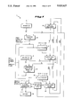
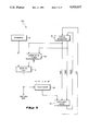
- FIG. 1 is a block diagram of a radix-16 divider in accordance with the present invention.
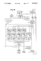
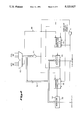
- FIG. 2 depicts a portion of the divider of FIG. 1 in more detail.
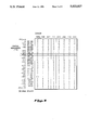
- FIG. 3 depicts a selection table of quotient bits.
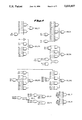
- FIG. 4 is a schematic diagram of an implementation of the selection table.
- FIG. 5 depicts an improved radix-4 divider.
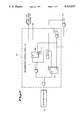
- FIG. 6 is an implementation of the quotient assimilator depicted in block-diagram form in FIG. 1.
- FIG. 7 illustrates a portion of the quotient assimilators of FIG. 6 in more detail.
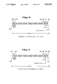
- FIGS. 8 and 9 illustrate the rounding process for the cases, respectively, in which the quotient is less than one, and in which the quotient is greater than or equal to one.
- FIGS. 10 and 11 depict an implementation of the quotient correction and rounding scheme used.
- a divider 1 in accordance with the invention is depicted in FIG. 1.
- a register 5 is loaded with the divisor D.
- a register 10 is loaded with the initial partial remainder (PR) of the division, i.e., the dividend.
- PR partial remainder
- the register 10 is a dual register for storing subsequent partial remainders in the redundant form of sum and carry outputs of a carry-save adder; the dividend, however, is loaded into the register 10 in irredundant (i.e., non-redundant) form (i.e., as a sum with the carry vector set to all zeros).
- the five most significant bits of the divisor (register 5) are fed as inputs to a selection logic 15.
- the six most significant bits of the partial remainder PR (register 10) are fed as inputs to the selection logic 15. It can be shown that it is sufficient to use only five and six bits of the divisor and partial remainder, respectively, in the selection process described below.
- the selection logic 15 is an array of logic used to generate a pair of quotient bits as an output in response to the divisor and partial remainder inputs.
- the selection logic 15 is used only for the very first pair of quotient bits and is bypassed thereafter.
- the output of the selection logic 15 is fed as a controlling input to a multiplexer 20 (e.g., a Booth multiplexer) that has five additional data inputs of -2D, -1D, 0, +1D, and +2D.
- the output of the multiplexer 20 is fed as an input to a carry-save adder 25.
- the carry-save adder 25 receives input from the multiplexer 20 and from the partial remainder register 10. It adds these two inputs and generates a new partial remainder as its output. This output (sum and carry) is fed to an overlapped quotient bit selection logic 30, which receives as another input five bits from the divisor D (register 5). The overlapped quotient bit selection logic 30 generates a second pair of quotient bits, which serve as control inputs for a multiplexer 35 (e.g., a Booth multiplexer).
- a multiplexer 35 e.g., a Booth multiplexer
- the overlapped quotient bit selection logic 30 generates the first pair of quotient bits for the succeeding cycle, which bits are fed as control input to the multiplexer 20 in lieu of the output of the selection logic 15.
- the multiplexer 35 has as data inputs -2D, -1D, 0, -1D, and +2D.
- the output of the multiplexer 35 is directed to a carry-save adder 40, which adds the outputs from the carry-save adder 25 (sum and carry) and the multiplexer output 35 to produce a new partial remainder for loading into the partial remainder register 10.
- the output of the selection logic 15 is the first quotient bit pair to be produced on the first cycle. This pair is produced in redundant form, i.e., it consists of negative quotient bits and positive quotient bits. Similarly, the outputs of the overlapped quotient bit selection logic 30 comprise a second quotient bit pair also in redundant form, i.e., as negative and positive quotient bits. These negative and positive quotient bits are fed as inputs to a quotient assimilator 45.
- the quotient assimilator 45 also receives input from quotient rounding logic 55. In turn, the quotient assimilator 45 delivers output to quotient rounding logic 55. Quotient rounding logic 55 also receives as input one bit from the partial remainder 10. The output of the quotient assimilator 45 is the quotient 50.
- the division method discussed here entails a left shift in (i.e., multiplication by two of) the partial remainder after each addition operation, so that more bits of the dividend are brought into the partial remainder.
- a shift of two binary places i.e., multiplication by four occurs after each addition, since each of the radix-4 dividers employed divides 2 bits at a time.
- this shift is accomplished by wiring the third through eighth most significant bits of the output of the carry-save adder 25 (representing the first new partial remainder generated in a cycle) to the six most significant bits of the input of the overlapped quotient bit selection logic 30 (as discussed in more detail below). This has the effect of "shifting" the output of the carry-save adder 25 leftward by two bits.
- the full-width output of the carry-save adder 25 is wired in similar fashion to each of the inputs of the carry-save adder 40, whose output in turn is wired in the same manner to the input of the partial remainder register 10.
- the selection logic 15 is used to determine the appropriate multiple of the divisor D (-2D, -D, 0, +D, or +2D) to add to the current partial remainder (register 10) to form the new partial remainder (output of the carry save adder 25).
- FIG. 3 a specification for a quotient bits selection table, describes the inputs and possible outputs the selection logic 15.
- the Figure details the quotient bits that are selected by the selection logic 15 depending on five bits of the divisor and six bits of the partial remainder.
- the normalized mantissa of the divisor will always be between the values 1/2 and 1 (i.e., it will be of the form 0.1xxxx . . . ).
- the five bits used are the five bits immediately to the right of the radix point.
- the six most significant bits of the PR are used, as indicated in FIG. 3.
- the row headings of FIG. 3 represent the possible values of the partial remainder (to three fraction bits of accuracy).
- the column headings of FIG. 3 represent the possible values of the normalized divisor D (to four or, in two cases, five fraction bits of accuracy).
- the divisor D to four fraction bits of accuracy, equals 0.1011
- the partial remainder PR to three fraction bits of accuracy, equals 000.101.
- the selection logic 15 selects -1, indicating that -1 times D should be added to the current PR to produce the new PR.
- FIG. 3 also details the correct choice for when the current partial remainder is outside the range of the numbers shown; for any value of the current PR greater than 1.5, -2 is the correct choice; similarly, for any value of the PR less than -1.5, +2 is correct.
- selection logic 15 is discussed below in conjunction with the logically equivalent selection logics of the overlapping quotient bit selector logic 30.
- the overlapping quotient bit selection logic 30 multiplexes five individual selection logics in parallel. Thus, all possible cases of the second selection (corresponding respectively to -2D, -1D, 0, +1D, and +2D) are performed for the second selection at the same time that the first selection is being performed.
- the resultant partial remainder can then be used in selecting the next partial remainder with reduced delay.
- the first two quotient bits and the second two quotient bits are selected approximately simultaneously.
- the output of the carry-save adder 25 is also fanned out as input to an assimilation adder 130, which may be a conventional carry-lookahead adder, as indicated in FIG. 2.
- an assimilation adder 130 which may be a conventional carry-lookahead adder, as indicated in FIG. 2.
- the outputs of the carry-save adders 60, 65, 70, and 75 are fed respectively as inputs to assimilation adders 110, 115, 120, and 125, which may be of the same kind as the assimilation adder 130.
- Each of these assimilation adders converts the output of its carry-save adder 25 to nonredundant form.
- the outputs of the assimilation adders are fed as inputs respectively to selection logics 80, 85, 90, 95, and 100.
- Each of these selection logics is logically equivalent to the first selection logic 15.
- the selection logic 80 computes the quotient bit selection for the case -2D; the selection logic 85 computes for the case -1D, and so on as indicated in FIG. 3.
- the selection logic 100 computes the selection for the case in which 0 is added to the first partial remainder generated in any given cycle, i.e., to the output of the carry-save adder 25.
- selection logics 80, 85, 90, 95, and 100 is depicted in FIG. 4.
- the implementation shown uses inputs only from the second- through fifth-most significant bits of the divisor D; since the most significant bit is known always to be 1, the logic is designed accordingly.
- Many equivalent implementations of AND-OR and related logic may be utilized, as will be appreciated by those of ordinary skill having the benefit of this disclosure.
- the inputs A6 through Al are from the partial-remainder output of one of the assimilation adders 110, 115, 120, 125, and 130; A6 is most significant. (On the first cycle, A6 through A1 come from the dividend.)
- Inputs D22 through D19 are from the divisor.
- Intermediate results SEL0P (for +0D) and SEL0N (for -0D) enable output SEL0 which selects 0 times the divisor.
- SEL2P1 and SEL2P2 both enable output SEL2P to select +2 times the divisor.
- SEL2N1 and SEL2N2 both assert the output SEL2N to select -2 times the divisor.
- the outputs of the selection logics 80, 85, 90, 95, and 100 are fed as data inputs to a multiplexer 105.
- the selection logic 100 additionally produces the second pair of quotient bits in the cycle and provides control inputs for both the multiplexer 105 and the multiplexer 35.
- the multiplexer 105 generates the first two quotient bits of the next cycle. These quotient bits are stored momentarily in latch 106 so that they may be input to the quotient assimilator 45 at the same time as the second pair of quotient bits for that cycle. In addition, the multiplexer 105 provides a control input for the multiplexer 20. This control input, on the second and subsequent cycles of the divider, takes the place of the output of the selection logic 15, which provided the control input on the first cycle.
- the first two quotient bits of the first cycle are generated by the selection logic 15; the second two quotient bits of the first cycle are generated by the overlapping quotient bit selection logic 30, meaning effectively by the selection logic 100.
- the first two quotient bits are generated by the multiplexer 105 (and stored in the latch 106), and the second two bits are again generated by the selection logic 100.
- the size of the carry-save adders 60, 65, 70, and 75 can be reduced from a large number of bits (54 bits is common) to only eight bits wide, thus achieving significant hardware savings.
- the assimilation adders 110, 115, 120, 125, and 130 may also be of reduced size.
- This reduction may allow the entire overlapping quotient bit selection logic 30 to be placed on a single integrated circuit, with the remaining logic of the radix-16 divider 1 to be placed on a second integrated circuit if necessary.
- the quotient assimilator 45 advantageously performs "on-the-fly" assimilation, to irredundant form, of the quotient bits selected by the selection logic 15 and the overlapping quotient bit selection logic 30.
- the quotient bit pairs produced by the divider 1 are in redundant form. In other words, if any given quotient bit pair is negative (as determined by the appropriate selection logic), the bits are stored in a negative quotient register; if the selected quotient bit pair is positive, it is stored in a positive quotient register.
- each of the negative and positive quotient registers represents only part of the quotient.
- the complete quotient (before rounding and correction) is conventionally arrived at by adding these two registers together at the end of the division process. (The use of negative and positive quotient registers in redundant division pro Rous is well-known and is not illustrated in the Figures.)
- the quotient bits that are generated in each cycle of the divider 1 are assimilated "on the fly” to reduce the carry time and also reduce the complexity of the adder needed to ripple the carry.
- the negative and positive quotient registers are added together to generate a sum bit group and a carry-out.
- the final value of any Jth group of quotient bits, formed by any Jth cycle, may be determined with exactness after it has been determined whether a carry will ripple into that group from the (J+1)th group (i.e., the next less significant group).
- a carry will not propagate into the Jth group if the bits of the (J+1)th group include one or more zeros, even if a carry-in is input into the (J+1)th group from the (J+2)th group.
- the bits of the (J+1)th group comprise all ones, not enough information is available to determine whether whether a carry-in to the Jth group might occur.
- the first quotient bits are generated in redundant form. In other words, a set of four first negative quotient bits and a separate set of four first positive quotient bits are generated. These two first sets of four bits each are added together and any carry out is thrown away, in the conventional manner for two's complement arithmetic.
- the second set of four negative and positive quotient bits are generated and added together in the same manner. Any carry-out from the second group is then added to the first group as a carry-in.
- the second group does not comprise all ones, it is therefore known that the first group is exact (because any carry-in to the second group will not propagate through to the first group).
- the second group does comprise all ones, any subsequent carry-in to the second group from the third group will ripple through into the first group.
- the third group also comprises all ones, then the first group is still inexact, because any carry into the third group will ripple through both the third and the second groups and into the first group.
- the carry-out of each newly arrived group determines, exactly, all of the outstanding inexact groups. If this carry-out is one, then all inexact groups must be incremented by one to make them exact; if this carry-out is zero, the inexact groups are left alone and become exact as-is.
- a feature of this invention is that inexactness of groups of four is kept with the groups and the increment, if needed, ripples across at most a group of four bits. Furthermore, the exactness of the first group of four (i.e., the group determining whether the quotient is less than one, or greater than or equal to one) is determined with reduced hardware and time.
- FIG. 6 depicts a quotient assimilation adder in accordance with this aspect of the invention.
- a sum bit group of four quotient bits 140 is generated by an adder 135 which adds these negative and positive quotient bits together. These four quotient bits are fed as inputs to carry propagation detection logic 145 (shown as implemented with an AND gate) for determining carry propagation and generating a carry-propagate signal. The addition of positive and negative quotient bits by the adder 135 results in a carry-out signal 165.
- the group of four quotient bits 140 is fed to each of a plurality of incrementers 170 via a signal router.
- the signal router delivers to each Jth incrementer 170 only the quotient bits associated with the Jth cycle. This may be accomplished, e.g., by clocking a bus only on the Jth cycle in a manner well-known to those of ordinary skill and therefore not shown.
- Each of a plurality of incrementer control logics 175 is fed with the carry-propagate signal 145 and the carryout signal 165.
- the particular incrementer control logic 175 designated as the Jth such logic in FIG. 6 is the one that delivers a carry-in to the Jth incrementer 170.
- Each four-bit incrementer 170 thus has four quotient bits as input, and a carry-in signal from its corresponding incrementer control logic 175 (shown immediately to the right in FIG. 6).
- Jth incrementer control logics 175 Each such logic will cause a carry-in to its corresponding Jth incrementer 170 if either of the following cases is true:
- Each Jth incrementer control logic 175 stores in latches (described below) the values of the carry-propagate and carry-out signals 145 and 165 of the (J+1)th four-bit group, and also receives as input the carry-out 165 of each four-bit group.
- FIG. 7 gives a more detailed representation of one of the incrementer control logics 175 used in the quotient assimilator 45.
- the incrementer control logic 175 may be implemented using common logic circuitry which is well-known to one of ordinary skill.
- the carry-propagate and carry-out signals 145 and 165 of the (J+1)th four-bit group may be routed to the Jth incrementer control logics 175 through a signal router such as described earlier, e.g., by appropriate clocking of a bus.
- Each incrementer control logic 175 includes a first latch 180 for storing the signal from carry-propagate logic 145.
- the latch 180 in the Jth incrementer control logic 175 is set if the four bits on the (J+1)th cycle comprise all ones; it is clocked by a system clock (shown in the Figures as t1); and it is cleared if and when the carry-out of any subsequent cycle is set.
- This clearing mechanism is shown in FIGS. 6 and 7 as the logical AND of the carry-out 165 and a signal marked t4, which is to indicate that the clocking mechanism should cause this signal to be asserted on a later phase of the system clock cycle, to provide sufficient delay that the latch 180 will not be cleared too soon.
- Each Jth incrementer control- logic 175 also includes a second latch 185 for storage of carry-out information relating to the Jth group of four quotient bits 140.
- the latch 185 in the Jth incrementer control logic 175 is set if either (a) the (J+1)th cycle generates a carry-out or (b) if the (J+1)th cycle is in carry-propagate mode and a (J+n)th cycle, n > 1, generates a carry-out.
- the latch 185 is also clocked by a system clock (shown as t1 in FIG. 7).
- a signal representing the carry-out of the last cycle is also fed as an input to each Jth incrementer control logic 175.
- the carry out from the very last cycle must ripple all the way up to the (J+1)th group--meaning that the (J+1)th group and all subsequent groups are not finally determined until the last cycle.
- the carry-out signal from the last cycle is therefore fed to each Jth incrementer control logic 175, there to be ANDed with the latched carry-propagate signal 180 from the (J+1)th group. If this latch is still set by the time a carry-out of 1 is generated from the last cycle (i.e., if the (J+1)th group is still in carry-propagate mode), it follows that all groups between the last group and the (J+1)th group are still in carry-propagate mode, and the carry generated by the last group will ripple all the way to the Jth group.
- the Jth incrementer control logic 175 therefore gates the Jth incrementer 170.
- the signal router may equivalently be implemented through the use of demultiplexers to route the four-quotient-bit signals 140, the carry-propagate signals 145, and the carry-out signals 165, to the correct incrementers 170 and incrementer control logics 175.
- quotient rounding and correction are performed approximately concurrently. This requires determination of where in the quotient to add 1 for quotient rounding.
- quotient rounding is not necessarily constant from quotient to quotient.
- floating point quotients are represented in a binary format that has a precision of a certain number of places or bits.
- a common format includes a 24-bit precision--only the most significant 24 bits of a quotient mantissa are kept.
- the number of fractional bits in the mantissa--and therefore the location of the proper bit to be incremented for rounding of a quotient in such a format--necessarily depends on the value of the mantissa. If the mantissa is less than 1, then of course all 24 kept bits are fractional (i.e., no bits are kept above the radix point). On the other hand, if the mantissa is 1 or greater (but by definition is less than 2), then only 23 kept bits of the mantissa are fractional.
- the least significant kept bit (LSKB) of the quotient is the 24th fraction al bit QB2.
- Rounding is thus performed by adding 1/2 LSKB to the quotient mantissa, i.e., by adding 1 to QB1, which is the 25th fractional bit and the rounding bit.
- the rounding bit is the 24th fractional bit QB2.
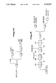
- FIGS. 10 and 11 illustrate logic which may be used to determine correct quotient rounding and correction.
- FIG. 10 shows circuitry to determine whether the quotient is 1 or greater. If bit QB26 is 1, then plainly the quotient value is one or greater, and so the rounding bit is therefore QB2 as explained above.
- the quotient will ripple upward to become greater than one if (a) it is not already one or greater (i.e., QB26 is not set), and (b) QB25 is set, and (c) QB24 is set, and (d) either of the following two cases is true:
- MSG most significant group
- CO msg-1 carry-in
- the most significant group is inexact (i.e., CP msg-1 is 1) and the two most significant bits of the final group of 4 (QB2 and QB3) are set.
- the existence of conditions causing the quotient to be one or greater are detected and the rounding and correction are done simultaneously.
- the slow conventional method of rippling the quotient from the least significant bit to the most significant bit is avoided, by providing a quotient assimilator that is greatly reduced in circuitry to achieve the same results in a much shorter time.
- This may be implemented in logic such as that depicted in FIG. 10; the result may be used as is shown in FIG. 11 to add the rounding bit in the appropriate place.
- FIG. 11 shows circuitry for incrementing the correct rounding bit and for performing quotient correction.
- the designations "HA” and “FA” shown in the Figure refer respectively to a half-adder or incrementer (which has one input plus a carry-in and carry-out) and a full adder (which has two inputs plus a carry-in and carry-out).
- the symbol SIGN - FPR designates the sign of the final partial remainder, which is readily obtained from the partial remainder register 10.
- the carry-out of an incrementer 190 (i.e., the carry-out of the group of 4 bits generated by the divider 1) is input to the rest of the quotient assimilator as is illustrated in FIGS. 6 and 7.
- a one's-complement conversion must eventually be performed, because addition of the negative and positive quotient bits as shown in FIG. 6 yields a sum 140 and carry-out 165 which are correct values in the one's complement format. It is therefore ordinarily desirable to convert the value of the final quotient back to two's complement.
- the logic depicted in FIG. 11 implements this correction scheme.
Abstract
Description
p.sub.j+1 =rp.sub.j -q.sub.j+1 d (1)
0 ≦ FPR < D (2)
Claims (5)
Priority Applications (7)
| Application Number | Priority Date | Filing Date | Title |
|---|---|---|---|
| US07/233,378 US5023827A (en) | 1988-08-18 | 1988-08-18 | Radix-16 divider using overlapped quotient bit selection and concurrent quotient rounding and correction |
| CA000608595A CA1332196C (en) | 1988-08-18 | 1989-08-17 | Radix-16 divider using overlapped quotient bit selection and concurrent quotient rounding and correction |
| DE68924386T DE68924386T2 (en) | 1988-08-18 | 1989-08-17 | Method and device for radix 2 ** n division with overlapping quotient bit selection and simultaneous rounding and correction of the quotient. |
| AT89308375T ATE128564T1 (en) | 1988-08-18 | 1989-08-17 | METHOD AND DEVICE FOR RADIX-2::N DIVISION WITH OVERLAPPING QUOTIENT BIT SELECTION AND SIMULTANEOUS ROUNDING AND CORRECTION OF THE QUOTIENT. |
| EP89308375A EP0356153B1 (en) | 1988-08-18 | 1989-08-17 | Radix-2**n divider method and apparatus using overlapped quotient bit selection and concurrent quotient rounding and correction |
| JP1212866A JPH0833817B2 (en) | 1988-08-18 | 1989-08-18 | Radix 16 divider |
| US07/602,721 US5132925A (en) | 1988-08-18 | 1990-10-24 | Radix-16 divider using overlapped quotient bit selection and concurrent quotient rounding and correction |
Applications Claiming Priority (1)
| Application Number | Priority Date | Filing Date | Title |
|---|---|---|---|
| US07/233,378 US5023827A (en) | 1988-08-18 | 1988-08-18 | Radix-16 divider using overlapped quotient bit selection and concurrent quotient rounding and correction |
Related Child Applications (1)
| Application Number | Title | Priority Date | Filing Date |
|---|---|---|---|
| US07/602,721 Division US5132925A (en) | 1988-08-18 | 1990-10-24 | Radix-16 divider using overlapped quotient bit selection and concurrent quotient rounding and correction |
Publications (1)
| Publication Number | Publication Date |
|---|---|
| US5023827A true US5023827A (en) | 1991-06-11 |
Family
ID=22876985
Family Applications (1)
| Application Number | Title | Priority Date | Filing Date |
|---|---|---|---|
| US07/233,378 Expired - Lifetime US5023827A (en) | 1988-08-18 | 1988-08-18 | Radix-16 divider using overlapped quotient bit selection and concurrent quotient rounding and correction |
Country Status (6)
| Country | Link |
|---|---|
| US (1) | US5023827A (en) |
| EP (1) | EP0356153B1 (en) |
| JP (1) | JPH0833817B2 (en) |
| AT (1) | ATE128564T1 (en) |
| CA (1) | CA1332196C (en) |
| DE (1) | DE68924386T2 (en) |
Cited By (14)
| Publication number | Priority date | Publication date | Assignee | Title |
|---|---|---|---|---|
| US5206828A (en) * | 1990-04-02 | 1993-04-27 | Advanced Micro Devices, Inc. | Special carry save adder for high speed iterative division |
| US5239498A (en) * | 1992-08-31 | 1993-08-24 | Intel Corporation | Methods and apparatus for improved quotient correction in nonrestoring division computation circuits |
| US5513132A (en) * | 1990-10-10 | 1996-04-30 | Hal Computer Systems, Inc. | Zero latency overhead self-timed iterative logic structure and method |
| US5729481A (en) * | 1995-03-31 | 1998-03-17 | International Business Machines Corporation | Method and system of rounding for quadratically converging division or square root |
| US5787030A (en) * | 1995-07-05 | 1998-07-28 | Sun Microsystems, Inc. | Correct and efficient sticky bit calculation for exact floating point divide/square root results |
| US5870323A (en) * | 1995-07-05 | 1999-02-09 | Sun Microsystems, Inc. | Three overlapped stages of radix-2 square root/division with speculative execution |
| US20040230634A1 (en) * | 2003-05-12 | 2004-11-18 | International Business Machines Corporation | Method and system for determining quotient digits for decimal division in a superscaler processor |
| US20060129625A1 (en) * | 2004-12-15 | 2006-06-15 | Sun Microsystems, Inc. | Low latency integer divider and integration with floating point divider and method |
| US20060129623A1 (en) * | 2004-12-15 | 2006-06-15 | Nec Corporation | Division and square root arithmetic unit |
| US20090006509A1 (en) * | 2007-06-28 | 2009-01-01 | Alaaeldin Amin | High-radix multiplier-divider |
| US20100191934A1 (en) * | 1991-06-24 | 2010-07-29 | Renesas Technology Corp. | Microcomputer and dividing circuit |
| US20100250639A1 (en) * | 2009-03-31 | 2010-09-30 | Olson Christopher H | Apparatus and method for implementing hardware support for denormalized operands for floating-point divide operations |
| US9086890B2 (en) | 2012-01-06 | 2015-07-21 | Oracle International Corporation | Division unit with normalization circuit and plural divide engines for receiving instructions when divide engine availability is indicated |
| US11500612B2 (en) * | 2020-02-14 | 2022-11-15 | Arm Limited | Method, system and device for multi-cycle division operation |
Families Citing this family (5)
| Publication number | Priority date | Publication date | Assignee | Title |
|---|---|---|---|---|
| JP2835153B2 (en) * | 1990-06-25 | 1998-12-14 | 株式会社東芝 | High radix divider |
| US5258944A (en) * | 1992-09-01 | 1993-11-02 | Cray Research, Inc. | High performance mantissa divider |
| JPH06282416A (en) * | 1993-03-30 | 1994-10-07 | Mitsubishi Electric Corp | Divider and computer equipped with the same |
| US6716232B1 (en) | 1993-04-30 | 2004-04-06 | United States Surgical Corporation | Surgical instrument having an articulated jaw structure and a detachable knife |
| DE10021920C1 (en) | 2000-05-05 | 2001-07-26 | Infineon Technologies Ag | Data processing method for modulo calculation of division remainder has whole number represented by partial data words with calculation of argument via recursive steps |
Citations (10)
| Publication number | Priority date | Publication date | Assignee | Title |
|---|---|---|---|---|
| US3970993A (en) * | 1974-01-02 | 1976-07-20 | Hughes Aircraft Company | Cooperative-word linear array parallel processor |
| US4320464A (en) * | 1980-05-05 | 1982-03-16 | Control Data Corporation | Binary divider with carry-save adders |
| US4484259A (en) * | 1980-02-13 | 1984-11-20 | Intel Corporation | Fraction bus for use in a numeric data processor |
| US4503512A (en) * | 1982-02-22 | 1985-03-05 | Amdahl Corporation | Cellular division circuit |
| US4722069A (en) * | 1984-04-09 | 1988-01-26 | Fujitsu Limited | Nonrestoring divider |
| US4724529A (en) * | 1985-02-14 | 1988-02-09 | Prime Computer, Inc. | Method and apparatus for numerical division |
| US4758972A (en) * | 1986-06-02 | 1988-07-19 | Raytheon Company | Precision rounding in a floating point arithmetic unit |
| US4758974A (en) * | 1985-01-29 | 1988-07-19 | American Telephone And Telegraph Company, At&T Bell Laboratories | Most significant digit location |
| US4760550A (en) * | 1986-09-11 | 1988-07-26 | Amdahl Corporation | Saving cycles in floating point division |
| US4817048A (en) * | 1986-08-11 | 1989-03-28 | Amdahl Corporation | Divider with quotient digit prediction |
Family Cites Families (2)
| Publication number | Priority date | Publication date | Assignee | Title |
|---|---|---|---|---|
| JPS60160438A (en) * | 1984-01-31 | 1985-08-22 | Fujitsu Ltd | Dividing device |
| JPS6175433A (en) * | 1984-09-20 | 1986-04-17 | Hitachi Ltd | Dividing device |
-
1988
- 1988-08-18 US US07/233,378 patent/US5023827A/en not_active Expired - Lifetime
-
1989
- 1989-08-17 CA CA000608595A patent/CA1332196C/en not_active Expired - Fee Related
- 1989-08-17 DE DE68924386T patent/DE68924386T2/en not_active Expired - Fee Related
- 1989-08-17 AT AT89308375T patent/ATE128564T1/en not_active IP Right Cessation
- 1989-08-17 EP EP89308375A patent/EP0356153B1/en not_active Expired - Lifetime
- 1989-08-18 JP JP1212866A patent/JPH0833817B2/en not_active Expired - Lifetime
Patent Citations (10)
| Publication number | Priority date | Publication date | Assignee | Title |
|---|---|---|---|---|
| US3970993A (en) * | 1974-01-02 | 1976-07-20 | Hughes Aircraft Company | Cooperative-word linear array parallel processor |
| US4484259A (en) * | 1980-02-13 | 1984-11-20 | Intel Corporation | Fraction bus for use in a numeric data processor |
| US4320464A (en) * | 1980-05-05 | 1982-03-16 | Control Data Corporation | Binary divider with carry-save adders |
| US4503512A (en) * | 1982-02-22 | 1985-03-05 | Amdahl Corporation | Cellular division circuit |
| US4722069A (en) * | 1984-04-09 | 1988-01-26 | Fujitsu Limited | Nonrestoring divider |
| US4758974A (en) * | 1985-01-29 | 1988-07-19 | American Telephone And Telegraph Company, At&T Bell Laboratories | Most significant digit location |
| US4724529A (en) * | 1985-02-14 | 1988-02-09 | Prime Computer, Inc. | Method and apparatus for numerical division |
| US4758972A (en) * | 1986-06-02 | 1988-07-19 | Raytheon Company | Precision rounding in a floating point arithmetic unit |
| US4817048A (en) * | 1986-08-11 | 1989-03-28 | Amdahl Corporation | Divider with quotient digit prediction |
| US4760550A (en) * | 1986-09-11 | 1988-07-26 | Amdahl Corporation | Saving cycles in floating point division |
Non-Patent Citations (15)
| Title |
|---|
| D. E. Atkins, Higher Radix Division Using Estimates of the Divisor and Partial Remainders, (1968), IEEE Trans. on Computer, vol. C 17, No. 10, pp. 925 934. * |
| D. E. Atkins, Higher Radix Division Using Estimates of the Divisor and Partial Remainders, (1968), IEEE Trans. on Computer, vol. C-17, No. 10, pp. 925-934. |
| G. S. Taylor, Radix 16 SRT Division with Overlapped Quotient Selection Stages, (1985), IEEE, pp. 64 71. * |
| G. S. Taylor, Radix 16 SRT Division with Overlapped Quotient Selection Stages, (1985), IEEE, pp. 64-71. |
| J. B. Gosling, Design of Arithmetic Units for Digital Computers, Chapter 5, (1980). * |
| Mifsud, "A Multipler Precision Division Algorithm", Comm. of the ACM, vol. 13, No. 11, Nov. 1970, pp. 666-668. |
| Mifsud, A Multipler Precision Division Algorithm , Comm. of the ACM, vol. 13, No. 11, Nov. 1970, pp. 666 668. * |
| Saltman, "Reducing Computing Time for Synchronous Binary Division", IRE Trans. on Electronic Computers, Jun. 1961, pp. 169-174. |
| Saltman, Reducing Computing Time for Synchronous Binary Division , IRE Trans. on Electronic Computers, Jun. 1961, pp. 169 174. * |
| Tam, "Transform High-Radix Division for High Performance Computer", IBM Tech. Discl. Bull., vol. 24, No. 11B, Apr. 1982, pp. 5812-5819. |
| Tam, Transform High Radix Division for High Performance Computer , IBM Tech. Discl. Bull., vol. 24, No. 11B, Apr. 1982, pp. 5812 5819. * |
| Tan, "High-Radix Division Quotient Selection by 2-Level Control Memories", IBM Tech. Discl. Bull., vol. 18, No. 3, Aug. 1975, pp. 837-839. |
| Tan, "High--Speed Decimal Division", IBM Tech. Discl. Bull., vol. 25, No. 1, Jun. 1982, pp. 77-83. |
| Tan, High Radix Division Quotient Selection by 2 Level Control Memories , IBM Tech. Discl. Bull., vol. 18, No. 3, Aug. 1975, pp. 837 839. * |
| Tan, High Speed Decimal Division , IBM Tech. Discl. Bull., vol. 25, No. 1, Jun. 1982, pp. 77 83. * |
Cited By (21)
| Publication number | Priority date | Publication date | Assignee | Title |
|---|---|---|---|---|
| US5206828A (en) * | 1990-04-02 | 1993-04-27 | Advanced Micro Devices, Inc. | Special carry save adder for high speed iterative division |
| US5513132A (en) * | 1990-10-10 | 1996-04-30 | Hal Computer Systems, Inc. | Zero latency overhead self-timed iterative logic structure and method |
| US5671151A (en) * | 1990-10-10 | 1997-09-23 | Hal Computer Systems, Inc. | Self-timed logic circuit having zero-latency overhead and method for designing same |
| US20100191934A1 (en) * | 1991-06-24 | 2010-07-29 | Renesas Technology Corp. | Microcomputer and dividing circuit |
| US5239498A (en) * | 1992-08-31 | 1993-08-24 | Intel Corporation | Methods and apparatus for improved quotient correction in nonrestoring division computation circuits |
| US5737255A (en) * | 1995-03-31 | 1998-04-07 | International Business Machines Corporation | Method and system of rounding for quadratically converging division or square root |
| US5729481A (en) * | 1995-03-31 | 1998-03-17 | International Business Machines Corporation | Method and system of rounding for quadratically converging division or square root |
| US5870323A (en) * | 1995-07-05 | 1999-02-09 | Sun Microsystems, Inc. | Three overlapped stages of radix-2 square root/division with speculative execution |
| US5954789A (en) * | 1995-07-05 | 1999-09-21 | Sun Microsystems, Inc. | Quotient digit selection logic for floating point division/square root |
| US5787030A (en) * | 1995-07-05 | 1998-07-28 | Sun Microsystems, Inc. | Correct and efficient sticky bit calculation for exact floating point divide/square root results |
| US20040230634A1 (en) * | 2003-05-12 | 2004-11-18 | International Business Machines Corporation | Method and system for determining quotient digits for decimal division in a superscaler processor |
| US7149767B2 (en) | 2003-05-12 | 2006-12-12 | International Business Machines Corporation | Method and system for determining quotient digits for decimal division in a superscaler processor |
| US20060129623A1 (en) * | 2004-12-15 | 2006-06-15 | Nec Corporation | Division and square root arithmetic unit |
| US7539720B2 (en) | 2004-12-15 | 2009-05-26 | Sun Microsystems, Inc. | Low latency integer divider and integration with floating point divider and method |
| US20060129625A1 (en) * | 2004-12-15 | 2006-06-15 | Sun Microsystems, Inc. | Low latency integer divider and integration with floating point divider and method |
| US7921149B2 (en) * | 2004-12-15 | 2011-04-05 | Nec Corporation | Division and square root arithmetic unit |
| US20090006509A1 (en) * | 2007-06-28 | 2009-01-01 | Alaaeldin Amin | High-radix multiplier-divider |
| US20100250639A1 (en) * | 2009-03-31 | 2010-09-30 | Olson Christopher H | Apparatus and method for implementing hardware support for denormalized operands for floating-point divide operations |
| US8452831B2 (en) | 2009-03-31 | 2013-05-28 | Oracle America, Inc. | Apparatus and method for implementing hardware support for denormalized operands for floating-point divide operations |
| US9086890B2 (en) | 2012-01-06 | 2015-07-21 | Oracle International Corporation | Division unit with normalization circuit and plural divide engines for receiving instructions when divide engine availability is indicated |
| US11500612B2 (en) * | 2020-02-14 | 2022-11-15 | Arm Limited | Method, system and device for multi-cycle division operation |
Also Published As
| Publication number | Publication date |
|---|---|
| DE68924386T2 (en) | 1996-06-13 |
| CA1332196C (en) | 1994-09-27 |
| DE68924386D1 (en) | 1995-11-02 |
| ATE128564T1 (en) | 1995-10-15 |
| JPH0833817B2 (en) | 1996-03-29 |
| EP0356153B1 (en) | 1995-09-27 |
| JPH02112023A (en) | 1990-04-24 |
| EP0356153A2 (en) | 1990-02-28 |
| EP0356153A3 (en) | 1992-10-07 |
Similar Documents
| Publication | Publication Date | Title |
|---|---|---|
| Swartzlander et al. | Computer arithmetic | |
| US5023827A (en) | Radix-16 divider using overlapped quotient bit selection and concurrent quotient rounding and correction | |
| US5132925A (en) | Radix-16 divider using overlapped quotient bit selection and concurrent quotient rounding and correction | |
| US5042001A (en) | Method and apparatus for performing mathematical functions using polynomial approximation and a rectangular aspect ratio multiplier | |
| US5046038A (en) | Method and apparatus for performing division using a rectangular aspect ratio multiplier | |
| US7395304B2 (en) | Method and apparatus for performing single-cycle addition or subtraction and comparison in redundant form arithmetic | |
| US5184318A (en) | Rectangular array signed digit multiplier | |
| JPH07182143A (en) | Method and apparatus for execution of division and square-root calculation in computer | |
| US5798955A (en) | High-speed division and square root calculation unit | |
| JPH0727456B2 (en) | Floating point arithmetic unit | |
| JPH0969040A (en) | Circuit for computing/dividing of square root of radical number 2 by three overlapped stages with presumptive computing | |
| US6728744B2 (en) | Wide word multiplier using booth encoding | |
| US5784307A (en) | Division algorithm for floating point or integer numbers | |
| US5144576A (en) | Signed digit multiplier | |
| US20090172069A1 (en) | Method and apparatus for integer division | |
| JP2585649B2 (en) | Division circuit | |
| US5357455A (en) | Floating point remainder generator for a math processor | |
| Bruguera | Radix-64 floating-point divider | |
| CN108334304B (en) | Digital recursive division | |
| US5818745A (en) | Computer for performing non-restoring division | |
| US7016930B2 (en) | Apparatus and method for performing operations implemented by iterative execution of a recurrence equation | |
| US6598065B1 (en) | Method for achieving correctly rounded quotients in algorithms based on fused multiply-accumulate without requiring the intermediate calculation of a correctly rounded reciprocal | |
| US4866655A (en) | Arithmetic processor and divider using redundant signed digit | |
| US4979141A (en) | Technique for providing a sign/magnitude subtraction operation in a floating point computation unit | |
| US5206825A (en) | Arithmetic processor using signed-digit representation of external operands |
Legal Events
| Date | Code | Title | Description |
|---|---|---|---|
| AS | Assignment |
Owner name: DIGITAL EQUIPMENT CORPORATION, 111 POWDERMILL RD., Free format text: ASSIGNMENT OF ASSIGNORS INTEREST.;ASSIGNOR:KEHL, THEODORE H.;REEL/FRAME:004937/0431 Effective date: 19880815 Owner name: DIGITAL EQUIPMENT CORPORATION, 111 POWDERMILL RD., Free format text: ASSIGNMENT OF ASSIGNORS INTEREST.;ASSIGNOR:CUTLER, DAVID N.;REEL/FRAME:004937/0432 Effective date: 19880815 |
|
| STCF | Information on status: patent grant |
Free format text: PATENTED CASE |
|
| FEPP | Fee payment procedure |
Free format text: PAYOR NUMBER ASSIGNED (ORIGINAL EVENT CODE: ASPN); ENTITY STATUS OF PATENT OWNER: LARGE ENTITY Free format text: PAT HLDR NO LONGER CLAIMS SMALL ENT STAT AS INDIV INVENTOR (ORIGINAL EVENT CODE: LSM1); ENTITY STATUS OF PATENT OWNER: LARGE ENTITY |
|
| FPAY | Fee payment |
Year of fee payment: 4 |
|
| FPAY | Fee payment |
Year of fee payment: 8 |
|
| AS | Assignment |
Owner name: COMPAQ INFORMATION TECHNOLOGIES GROUP, L.P., TEXAS Free format text: ASSIGNMENT OF ASSIGNORS INTEREST;ASSIGNORS:DIGITAL EQUIPMENT CORPORATION;COMPAQ COMPUTER CORPORATION;REEL/FRAME:012447/0903;SIGNING DATES FROM 19991209 TO 20010620 |
|
| FPAY | Fee payment |
Year of fee payment: 12 |
|
| AS | Assignment |
Owner name: HEWLETT-PACKARD DEVELOPMENT COMPANY, L.P., TEXAS Free format text: CHANGE OF NAME;ASSIGNOR:COMPAQ INFORMATION TECHNOLOGIES GROUP, LP;REEL/FRAME:015000/0305 Effective date: 20021001 |
|
| FEPP | Fee payment procedure |
Free format text: PAYOR NUMBER ASSIGNED (ORIGINAL EVENT CODE: ASPN); ENTITY STATUS OF PATENT OWNER: LARGE ENTITY Free format text: PAYER NUMBER DE-ASSIGNED (ORIGINAL EVENT CODE: RMPN); ENTITY STATUS OF PATENT OWNER: LARGE ENTITY |