US5012656A - Heat sink for a control device in an automobile air conditioning system - Google Patents
Heat sink for a control device in an automobile air conditioning system Download PDFInfo
- Publication number
- US5012656A US5012656A US07/488,106 US48810690A US5012656A US 5012656 A US5012656 A US 5012656A US 48810690 A US48810690 A US 48810690A US 5012656 A US5012656 A US 5012656A
- Authority
- US
- United States
- Prior art keywords
- evaporator
- control device
- power transistor
- conditioning system
- air conditioning
- Prior art date
- Legal status (The legal status is an assumption and is not a legal conclusion. Google has not performed a legal analysis and makes no representation as to the accuracy of the status listed.)
- Expired - Fee Related
Links
Images


Classifications
-
- F—MECHANICAL ENGINEERING; LIGHTING; HEATING; WEAPONS; BLASTING
- F25—REFRIGERATION OR COOLING; COMBINED HEATING AND REFRIGERATION SYSTEMS; HEAT PUMP SYSTEMS; MANUFACTURE OR STORAGE OF ICE; LIQUEFACTION SOLIDIFICATION OF GASES
- F25B—REFRIGERATION MACHINES, PLANTS OR SYSTEMS; COMBINED HEATING AND REFRIGERATION SYSTEMS; HEAT PUMP SYSTEMS
- F25B49/00—Arrangement or mounting of control or safety devices
- F25B49/02—Arrangement or mounting of control or safety devices for compression type machines, plants or systems
- F25B49/025—Motor control arrangements
-
- B—PERFORMING OPERATIONS; TRANSPORTING
- B60—VEHICLES IN GENERAL
- B60H—ARRANGEMENTS OF HEATING, COOLING, VENTILATING OR OTHER AIR-TREATING DEVICES SPECIALLY ADAPTED FOR PASSENGER OR GOODS SPACES OF VEHICLES
- B60H1/00—Heating, cooling or ventilating devices
- B60H1/00507—Details, e.g. mounting arrangements, desaeration devices
- B60H1/00514—Details of air conditioning housings
- B60H1/00521—Mounting or fastening of components in housings, e.g. heat exchangers, fans, electronic regulators
-
- B—PERFORMING OPERATIONS; TRANSPORTING
- B60—VEHICLES IN GENERAL
- B60H—ARRANGEMENTS OF HEATING, COOLING, VENTILATING OR OTHER AIR-TREATING DEVICES SPECIALLY ADAPTED FOR PASSENGER OR GOODS SPACES OF VEHICLES
- B60H1/00—Heating, cooling or ventilating devices
- B60H1/32—Cooling devices
- B60H1/3204—Cooling devices using compression
- B60H1/3229—Cooling devices using compression characterised by constructional features, e.g. housings, mountings, conversion systems
-
- G—PHYSICS
- G05—CONTROLLING; REGULATING
- G05D—SYSTEMS FOR CONTROLLING OR REGULATING NON-ELECTRIC VARIABLES
- G05D23/00—Control of temperature
- G05D23/19—Control of temperature characterised by the use of electric means
- G05D23/1919—Control of temperature characterised by the use of electric means characterised by the type of controller
Definitions
- the present invention generally relates to a heat sink for a control device in an automobile air conditioning system, and more particularly, to the positioning of a control device on the evaporator of an air conditioning refrigerant circuit so that heat is effectively transferred from the control device without impeding the flow of air through a duct which connects the evaporator to the automobile passenger compartment.
- an automobile air conditioning system includes a refrigerant circuit and an electric circuit comprising electric devices for operating various elements of the refrigerant circuit.
- a condenser fan motor operates in conjunction with a condenser of the refrigerant circuit, and a control apparatus which includes a control device, such as a power transistor, which is included with the electric circuit, which controls the operational condition of the condenser fan motor.
- Electric control devices likewise control various other electric devices which operate various refrigerant elements of the refrigerant circuit.
- heat generated in the control device during operation may damage the control device thereby detrimentally affecting control of the air conditioning system. Therefore, the control device must be cooled during operation of the air conditioning system to prevent thermal damage.
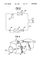
- FIG. 1 shows a portion of a conventional automobile air conditioning system.
- power transistor 100 is the control device of an electric control circuit.
- Power transistor 100 is mounted on a heat sink which includes a plurality of radiating plates 110 firmly secured to a top surface thereof, and is firmly attached to an inner surface of cover member 120 by a pair of screws 121.
- Cooling unit 50 comprises an evaporator (not shown) and casing 500 which is air tight and surrounds the evaporator while allowing air to pass through a heat exchanging portion of the evaporator.
- Casing 500 comprises two openings (only opening 501 is shown) opposing each other.
- Opening 501 of cooling unit 50 is opened to the outside, and the other opening is air tight and connected to one end (not shown) of duct 130.
- Duct 130 comprises opening 131 formed at a side surface thereof adjacent cooling unit 50. Opening 131 is adapted to accommodate power transistor 100 and its associated heat sink in duct 130. Cover member 131 forms an airtight seal around opening 131 by using a plurality of screws 132.
- the air outside cooling unit 50 is conducted into cooling unit 50 through opening 501 by operation of an evaporator fan (not shown) as depicted by arrow "A".
- the air in cooling unit 50 is cooled while passing through a heat exchanging portion of the evaporator.
- the cooled air subsequently flows into duct 130 through the opening of casing 500, opposite the air inlet, to be conducted into the passenger compartment of an automobile as depicted by arrow "B".
- a part of the cooled air in duct 130 is heat exchanged with plates 110 so as to prevent an excessive ries in the temperature of power transistor 100.
- thermal damage to power transistor 100 (the control device) is prevented and control of the air conditioning system is not detrimentally affected.
- FIG. 2 shows a block diagram of a refrigerant circuit of an automobile air conditioning system.
- refrigerant circuit 200 includes compressor 210, condenser 220, receiver-drier 230, thermostatic expansion valve 240 and evaporator 250 serially connected through pipe members 270.
- Cooling device 260 is disposed between evaporator 250 and compressor 210 through pipe members 270.
- Cooling device 260 has a power transistor incorporated therein, as the control device, of an electric control circuit for the automobile air conditioning system.
- the throttling condition of expansion valve 240 is varied in response to the temperature at an outlet of evaporator 250, located upstream with respect to cooling device 260, in order to maintain super heat at the outlet of evaporator 250 at a proper temperature.
- the power transistor is cooled by virtue of heat exchange between the suction refrigerant gas flowing through cooling device 260 in order to prevent the excessive rise in temperature of the power transistor. In this way, thermal damage to the power transistor (the control device) is prevented.
- an object to the present invention to provide an automobile air conditioning system in which thermal damage to a control device of an electric control circuit which effects control of the air conditioning system is prevented without impeding the flow of air in a duct conducting the air from an evaporator to a passenger compartment.
- a control apparatus for an electric circuit of an automobile air conditioning system comprises at least one control device.
- the automobile air conditioning system comprises a refrigerant circuit which includes a compressor, a condenser, an expansion device and an evaporator.
- the electric circuit associated therewith comprises at least one electric device which operates at least one of the elements of the refrigerant circuit.
- the at least one control device is fixedly attached to an exterior surface of the evaporator so as to conduct heat generated in the control device to the exterior surface of the evaporator.
- FIG. 1 is a perspective view of a certain portion of one commercial automobile air conditioning system.
- FIG. 2 is a block diagram of the refrigerant circuit of an automobile air conditioning system.
- FIG. 3 is a schematic block diagram of a compressor driving unit used for an automobile air conditioning system in accordance with one embodiment of the present invention.
- FIG. 4 is a perspective view of a power transistor unit and a part of an evaporator of the automobile air conditioning system in accordance with one embodiment of the present invention.
- FIG. 5 is a perspective view of a cooling unit of the automobile air conditioning system in accordance with one embodiment of the present invention.
- FIG. 3 shows a schematic block diagram of a compressor driving unit used for an automobile air conditioning system in accordance with one embodiment of the present invention.
- compressor driving unit 10 includes compressor 11, DC motor 12 and control device 13 controlling the rotational speed of DC motor 12 in response to an external signal, for example, the temperature of air in the passenger compartment. Rotational motion of DC motor 12 is transmitted to compressor 11 through coupling device 14 in order to drive compressor 11.
- Control device 13 includes power transistor 31, as shown in FIG. 4, to vary the amount of electric power applied to DC motor 12.
- Automobile engine 17 is coupled to alternator 16 through a belt 18 which drives alternator 16 thereby producing alternating current at the output of alternator 16.
- the alternating current from alternator 16 is supplied to rectifier 15 through wires 16a, and is rectified to provide direct current at the output of rectifier 15.
- the direct current from rectifier 15 is supplied to control device 13 through wires 15a, and the valvue thereof is varied in response to an external signal.
- Electric power from control device 13 is supplied to DC motor 12 through wires 13a, and the rotational speed of DC motor 12 is varied in response to changes in the amount of electric power applied thereto.
- the rotational energy of DC motor 12, having various speeds, is transmitted to compressor 11 through coupling device 14 in order to drive compressor 11 with the various operational conditions.
- the refrigerant gas is compressed by compressor 11, and is discharged to a condenser (not shown), and then sequentially flows to a receiver-drier (not shown), a thermostatic expansion valve (not shown) and evaporator 250, as shown in FIG. 4, with a change in the phase thereof.
- FIG. 4 shows a power transistor unit 30 and a part of an evaporator 250 of the automobile air conditioning system in accordance with one embodiment of the present invention.
- evaporator 250 includes, a serpentine-shape flat tube 251 comprising a plurality of straight portions 251a and plurality of corrugated fins 252 fixedly attached to and sandwiched by opposing straight portions 251a of serpentine-shaped flat tube 251.
- the Serpentine-shaped flat tube 251 and corrugated fins 252 jointly form heat exchange portion 25.
- the serpentine-shaped flat tube 251 is provided with an outlet pipe 253 at one end thereof so as to conduct the refrigerant gas into the inlet port of compressor 11.
- a pair of protective plates 254 (only one is shown) are securely joined to the outermost straight portions of flat tube 251 through corrugated fins 252.
- Power transistor unit 30 includes a conduction plate 32, power transistor 31 fixedly attached to the conduction plate 32 by using screws (not shown), and cover 33 for protecting the power transistor 31.
- Conduction plate 32 and cover 33 are fixedly secured to the protective plate 254 of evaporator 250 by using a plurality of screws 34 so as to make contact between the conduction plate 32 and an exterior surface of protective plate 254.
- Wires 15a and 13a connect power transistor 31 to rectifier 15 and motor 12, respectively.
- Wires 13a supply electric power having a variable value to DC motor 12.
- power transistor unit 30 protrudes from casing 500 through opening 502 formed at a side surface of casing 500 in order to facilitate ease in maintaining the power transistor.
- the air outside cooling unit 50 is conducted into cooling unit 50 through opening 501 of cooling unit 50 by operation of an evaporator fan (not shown) as depicted by arrow "A".
- the air in cooling unit 50 is cooled while passing through heat exchange portion 25 of evaporator 250 by virture of heat exchange with the refrigerant in flat tube 251.
- the cooled air subsequently flows into duct 130 to be conducted into the passage compartment as depicted by arrow "B".
- power transistor 31 is cooled by a well known manner in the art, in order to prevent an excessive rise in temperature thereof. Thus, thermal damage to power transistor 31 is prevented.
- the power transistor unit of the automobile air conditioning system is fixedly attached to an exterior surface of the evaporator, which is the coolest element of the refrigerant circuit, the excessive rise in temperature of the power transistor is prevented without impeding the flow of air in the duct which connects the cooling unit to the passenger compartment and without complicating the process of assembling the refrigerant circuit of the automobile air conditioning system.
Landscapes
- Engineering & Computer Science (AREA)
- Physics & Mathematics (AREA)
- Thermal Sciences (AREA)
- Mechanical Engineering (AREA)
- General Physics & Mathematics (AREA)
- Automation & Control Theory (AREA)
- General Engineering & Computer Science (AREA)
- Air-Conditioning For Vehicles (AREA)
Abstract
The present invention is directed to a heat sink for a control device in an electric circuit of an automobile air conditioning system. The control device includes a power transistor which varies the amount of electric power supplied to a motor, so as to vary the rotational speed of the motor in response to demand. The motor drives a compressor of a refrigerant circuit in order to change the driving condition of the compressor in response to change in the rotational speed thereof. The power transistor is fixedly attached to an exterior surface of an evaporator which is the coolest element of the refrigerant circuit in order to provide cooling therefor. Thus, an excessive rise in temperature of the power transistor is prevented without impeding the flow of air in a duct which conducts air from the evaporator to a passenger compartment and without complicating the process of assembling the refrigerant circuit of the automobile air conditioning system.
Description
1. Field of the Invention
The present invention generally relates to a heat sink for a control device in an automobile air conditioning system, and more particularly, to the positioning of a control device on the evaporator of an air conditioning refrigerant circuit so that heat is effectively transferred from the control device without impeding the flow of air through a duct which connects the evaporator to the automobile passenger compartment.
2. Description of the Prior Art
In general, an automobile air conditioning system includes a refrigerant circuit and an electric circuit comprising electric devices for operating various elements of the refrigerant circuit. For example, a condenser fan motor operates in conjunction with a condenser of the refrigerant circuit, and a control apparatus which includes a control device, such as a power transistor, which is included with the electric circuit, which controls the operational condition of the condenser fan motor. Electric control devices likewise control various other electric devices which operate various refrigerant elements of the refrigerant circuit. However, heat generated in the control device during operation may damage the control device thereby detrimentally affecting control of the air conditioning system. Therefore, the control device must be cooled during operation of the air conditioning system to prevent thermal damage.
FIG. 1 shows a portion of a conventional automobile air conditioning system. Referring to FIG. 1, power transistor 100 is the control device of an electric control circuit. Power transistor 100 is mounted on a heat sink which includes a plurality of radiating plates 110 firmly secured to a top surface thereof, and is firmly attached to an inner surface of cover member 120 by a pair of screws 121. Cooling unit 50 comprises an evaporator (not shown) and casing 500 which is air tight and surrounds the evaporator while allowing air to pass through a heat exchanging portion of the evaporator. Casing 500 comprises two openings (only opening 501 is shown) opposing each other. Opening 501 of cooling unit 50 is opened to the outside, and the other opening is air tight and connected to one end (not shown) of duct 130. Duct 130 comprises opening 131 formed at a side surface thereof adjacent cooling unit 50. Opening 131 is adapted to accommodate power transistor 100 and its associated heat sink in duct 130. Cover member 131 forms an airtight seal around opening 131 by using a plurality of screws 132.
In operation, the air outside cooling unit 50 is conducted into cooling unit 50 through opening 501 by operation of an evaporator fan (not shown) as depicted by arrow "A". The air in cooling unit 50 is cooled while passing through a heat exchanging portion of the evaporator. The cooled air subsequently flows into duct 130 through the opening of casing 500, opposite the air inlet, to be conducted into the passenger compartment of an automobile as depicted by arrow "B". In this arrangement, a part of the cooled air in duct 130 is heat exchanged with plates 110 so as to prevent an excessive ries in the temperature of power transistor 100. Thus, thermal damage to power transistor 100 (the control device) is prevented and control of the air conditioning system is not detrimentally affected.
However, in certain conventional automobile air conditioning systems, where electric devices are used which consume large amounts of electric power, the amount of heat generated in power transistor 100 is increased. Therefore, radiating plates 110 on the heat sink associated with power transistor 100 must have increased dimensions in order to prevent an excessive rise in the temperature of power transistor 100. The result is that air in duct 130 is not able to flow smoothly due to interference with both power transistor 100 and plates 110. Therefore, the evaporator fan wastefully consumes electric power in order to compensate for the interference with the flow of air in duct 130 caused by power transistor 100 and plates 110.
FIG. 2 shows a block diagram of a refrigerant circuit of an automobile air conditioning system. Referring to FIG. 2, refrigerant circuit 200 includes compressor 210, condenser 220, receiver-drier 230, thermostatic expansion valve 240 and evaporator 250 serially connected through pipe members 270. Cooling device 260 is disposed between evaporator 250 and compressor 210 through pipe members 270. Cooling device 260 has a power transistor incorporated therein, as the control device, of an electric control circuit for the automobile air conditioning system. The throttling condition of expansion valve 240 is varied in response to the temperature at an outlet of evaporator 250, located upstream with respect to cooling device 260, in order to maintain super heat at the outlet of evaporator 250 at a proper temperature. In this construction, the power transistor is cooled by virtue of heat exchange between the suction refrigerant gas flowing through cooling device 260 in order to prevent the excessive rise in temperature of the power transistor. In this way, thermal damage to the power transistor (the control device) is prevented.
However, in this automobile air conditioning system, further hermetic joints are required in the refrigerant circuit in order to dispose cooling device 260 between evaporator 250 and compressor 210. Therefore, the process of assembling the refrigerant circuit becomes more complicated.
Accordingly, it is an object to the present invention to provide an automobile air conditioning system in which thermal damage to a control device of an electric control circuit which effects control of the air conditioning system is prevented without impeding the flow of air in a duct conducting the air from an evaporator to a passenger compartment.
It is another object of the present invention to provide an automobile air conditioning system in which, the thermal damage to a control device of a control circuit which effects control of the air conditioning system is prevented, while at the same time not complicating the process of assembling a refrigerant circuit therefor.
A control apparatus for an electric circuit of an automobile air conditioning system comprises at least one control device. The automobile air conditioning system comprises a refrigerant circuit which includes a compressor, a condenser, an expansion device and an evaporator. The electric circuit associated therewith comprises at least one electric device which operates at least one of the elements of the refrigerant circuit. The at least one control device is fixedly attached to an exterior surface of the evaporator so as to conduct heat generated in the control device to the exterior surface of the evaporator.
FIG. 1 is a perspective view of a certain portion of one commercial automobile air conditioning system.
FIG. 2 is a block diagram of the refrigerant circuit of an automobile air conditioning system.
FIG. 3 is a schematic block diagram of a compressor driving unit used for an automobile air conditioning system in accordance with one embodiment of the present invention.
FIG. 4 is a perspective view of a power transistor unit and a part of an evaporator of the automobile air conditioning system in accordance with one embodiment of the present invention.
FIG. 5 is a perspective view of a cooling unit of the automobile air conditioning system in accordance with one embodiment of the present invention.
FIG. 3 shows a schematic block diagram of a compressor driving unit used for an automobile air conditioning system in accordance with one embodiment of the present invention. Referring to FIG. 3, compressor driving unit 10 includes compressor 11, DC motor 12 and control device 13 controlling the rotational speed of DC motor 12 in response to an external signal, for example, the temperature of air in the passenger compartment. Rotational motion of DC motor 12 is transmitted to compressor 11 through coupling device 14 in order to drive compressor 11. Control device 13 includes power transistor 31, as shown in FIG. 4, to vary the amount of electric power applied to DC motor 12. Automobile engine 17 is coupled to alternator 16 through a belt 18 which drives alternator 16 thereby producing alternating current at the output of alternator 16. The alternating current from alternator 16 is supplied to rectifier 15 through wires 16a, and is rectified to provide direct current at the output of rectifier 15. The direct current from rectifier 15 is supplied to control device 13 through wires 15a, and the valvue thereof is varied in response to an external signal. Electric power from control device 13 is supplied to DC motor 12 through wires 13a, and the rotational speed of DC motor 12 is varied in response to changes in the amount of electric power applied thereto. The rotational energy of DC motor 12, having various speeds, is transmitted to compressor 11 through coupling device 14 in order to drive compressor 11 with the various operational conditions. The refrigerant gas is compressed by compressor 11, and is discharged to a condenser (not shown), and then sequentially flows to a receiver-drier (not shown), a thermostatic expansion valve (not shown) and evaporator 250, as shown in FIG. 4, with a change in the phase thereof.
FIG. 4 shows a power transistor unit 30 and a part of an evaporator 250 of the automobile air conditioning system in accordance with one embodiment of the present invention. Referring to FIG. 4 in addition to FIG. 3, evaporator 250 includes, a serpentine-shape flat tube 251 comprising a plurality of straight portions 251a and plurality of corrugated fins 252 fixedly attached to and sandwiched by opposing straight portions 251a of serpentine-shaped flat tube 251. The Serpentine-shaped flat tube 251 and corrugated fins 252 jointly form heat exchange portion 25. The serpentine-shaped flat tube 251 is provided with an outlet pipe 253 at one end thereof so as to conduct the refrigerant gas into the inlet port of compressor 11. A pair of protective plates 254 (only one is shown) are securely joined to the outermost straight portions of flat tube 251 through corrugated fins 252.
Referring to FIG. 5 in addition to FIG. 4, when evaporator 250 is accommodated in casing 500 of cooling unit 50, power transistor unit 30 protrudes from casing 500 through opening 502 formed at a side surface of casing 500 in order to facilitate ease in maintaining the power transistor.
In operation, the air outside cooling unit 50 is conducted into cooling unit 50 through opening 501 of cooling unit 50 by operation of an evaporator fan (not shown) as depicted by arrow "A". The air in cooling unit 50 is cooled while passing through heat exchange portion 25 of evaporator 250 by virture of heat exchange with the refrigerant in flat tube 251. The cooled air subsequently flows into duct 130 to be conducted into the passage compartment as depicted by arrow "B". When the air in cooling unit 50 is heat exchanged with the refrigerant in flat tube 251, power transistor 31 is cooled by a well known manner in the art, in order to prevent an excessive rise in temperature thereof. Thus, thermal damage to power transistor 31 is prevented.
In the present invention, since the power transistor unit of the automobile air conditioning system is fixedly attached to an exterior surface of the evaporator, which is the coolest element of the refrigerant circuit, the excessive rise in temperature of the power transistor is prevented without impeding the flow of air in the duct which connects the cooling unit to the passenger compartment and without complicating the process of assembling the refrigerant circuit of the automobile air conditioning system.
While the invention has been described herein by reference to a preferred embodiment, various modifications can be made without departing from the true scope and spirit of the invention. It is intended, therefore, by the appended claims, to embody all such modifications.
Claims (5)
1. In an automobile air conditioning system including an electric circuit having at least one electric device and a refrigerant circuit formed by refrigerant elements such as a compressor, a condenser, an expansion element and an evaporator, wherein said evaporator is contained within a housing and wherein said housing is in turn connected to the passenger compartment of the automobile to be cooled by a duct, said electric circuit further including at least one control device associated therewith for controlling the operation of said at least one electric device to thereby control at least one of said elements of said refrigerant circuit, the improvement comprising;
said at least one control device being fixedly attached to an exterior surface of said evaporator so that heat generated by said at least one control device is conducted to said exterior surface of said evaporator which exterior surface is not direct contact with air flowing through the evaporator whereby the flow of air through the evaporator and duct to the passenger compartment is not impeded by the control device.
2. The electric circuit of claim 1 wherein said at least one control device is a power transistor.
3. The electric circuit of claim 2 wherein said at least one electric device is a motor.
4. The electric circuit of claim 3 wherein said motor drives said compressor.
5. The electric circuit of claim 4 wherein said power transistor varies the amount of electric power which is supplied to said motor so as to vary the rotational speed of said motor in response to demand.
Applications Claiming Priority (2)
| Application Number | Priority Date | Filing Date | Title |
|---|---|---|---|
| JP1-50098 | 1989-03-03 | ||
| JP1050098A JPH02231218A (en) | 1989-03-03 | 1989-03-03 | Cooling device for controller |
Publications (1)
| Publication Number | Publication Date |
|---|---|
| US5012656A true US5012656A (en) | 1991-05-07 |
Family
ID=12849595
Family Applications (1)
| Application Number | Title | Priority Date | Filing Date |
|---|---|---|---|
| US07/488,106 Expired - Fee Related US5012656A (en) | 1989-03-03 | 1990-03-05 | Heat sink for a control device in an automobile air conditioning system |
Country Status (6)
| Country | Link |
|---|---|
| US (1) | US5012656A (en) |
| EP (1) | EP0385766B1 (en) |
| JP (1) | JPH02231218A (en) |
| KR (1) | KR900014163A (en) |
| AU (1) | AU616105B2 (en) |
| DE (1) | DE69022607T2 (en) |
Cited By (16)
| Publication number | Priority date | Publication date | Assignee | Title |
|---|---|---|---|---|
| WO1997002729A1 (en) * | 1995-07-06 | 1997-01-23 | Danfoss A/S | Compressor with control electronics |
| US5669813A (en) * | 1996-05-03 | 1997-09-23 | Ford Motor Company | Apparatus for storing and cooling electronic devices and/or modules in a vehicle |
| US5675223A (en) * | 1995-05-25 | 1997-10-07 | Sanden Corp. | Circuit board unit for driving and controlling motor that drives compressor for air-conditioner |
| EP0933603A1 (en) * | 1998-01-30 | 1999-08-04 | RC Group S.p.A. | Cooling system having an inverter for controlling a compressor cooled by a fluid of the system and related process |
| US6318103B1 (en) * | 2000-09-22 | 2001-11-20 | Delphi Technologies, Inc. | Evaporator mounted blower speed control |
| SG84572A1 (en) * | 1999-03-15 | 2001-11-20 | Carrier Corp | Apparatus for cooling the power electronics of a refrigeration compressor drive |
| US20030034186A1 (en) * | 2001-07-18 | 2003-02-20 | Honda Giken Kogyo Kabushiki Kaisha | Power control unit for electric vehicle |
| US6675590B2 (en) | 1999-12-23 | 2004-01-13 | Grunfos A/S | Cooling device |
| US20050254212A1 (en) * | 2004-05-17 | 2005-11-17 | Eins Oe-Tech Co., Ltd. | Heat dissipation module for electronic device |
| US20070032909A1 (en) * | 2005-08-03 | 2007-02-08 | Tolbert John W Jr | System and method for compressor capacity modulation |
| DE102006004414A1 (en) * | 2006-01-31 | 2007-08-02 | Valeo Klimasysteme Gmbh | cooling unit |
| EP1835243A1 (en) | 2006-03-17 | 2007-09-19 | Delphi Technologies, Inc. | Evaporator with electronic circuit printed on a first side plate |
| US20090266091A1 (en) * | 2005-08-03 | 2009-10-29 | Bristol Compressors International, Inc. | System and method for compressor capacity modulation in a heat pump |
| US20090324428A1 (en) * | 2008-06-29 | 2009-12-31 | Tolbert Jr John W | System and method for detecting a fault condition in a compressor |
| US20100101242A1 (en) * | 2008-10-24 | 2010-04-29 | Enviro Systems, Inc. | System and method for cooling air conditioning system electronics |
| US8601828B2 (en) | 2009-04-29 | 2013-12-10 | Bristol Compressors International, Inc. | Capacity control systems and methods for a compressor |
Families Citing this family (3)
| Publication number | Priority date | Publication date | Assignee | Title |
|---|---|---|---|---|
| DE19908043C2 (en) * | 1999-02-24 | 2001-08-30 | Mannesmann Vdo Ag | Electrically driven compression refrigeration system of a motor vehicle |
| US6397609B1 (en) * | 1999-08-20 | 2002-06-04 | Denso Corporation | Vehicle air-conditioning system with arrangement of electrical member |
| US8400090B2 (en) | 2009-08-10 | 2013-03-19 | Emerson Electric Co. | HVAC condenser assemblies having controllable input voltages |
Citations (9)
| Publication number | Priority date | Publication date | Assignee | Title |
|---|---|---|---|---|
| US2966033A (en) * | 1958-12-03 | 1960-12-27 | Gen Motors Corp | Refrigerating apparatus |
| US3334684A (en) * | 1964-07-08 | 1967-08-08 | Control Data Corp | Cooling system for data processing equipment |
| US4326386A (en) * | 1979-09-18 | 1982-04-27 | Sankyo Electric Company Limited | Temperature control circuit for automobile air-conditioning system |
| US4546619A (en) * | 1984-06-25 | 1985-10-15 | Rohner Thomas G | Mechanical cooler for electronics |
| US4616693A (en) * | 1983-09-03 | 1986-10-14 | Sueddeutsche Kuehlerfabrik Julius Fr. Behr Gmbh & Co. Kg | Heating and/or air conditioning apparatus for automotive vehicles |
| US4697427A (en) * | 1985-05-10 | 1987-10-06 | Sundstrand Corporation | Forced flow evaporator for unusual gravity conditions |
| US4720981A (en) * | 1986-12-23 | 1988-01-26 | American Standard Inc. | Cooling of air conditioning control electronics |
| US4815658A (en) * | 1987-04-15 | 1989-03-28 | Sanden Corporation | Control device for automotive air conditioning system |
| US4832258A (en) * | 1987-04-15 | 1989-05-23 | Sanden Corporation | Measuring circuit for use in device for detecting ambient air temperature |
Family Cites Families (7)
| Publication number | Priority date | Publication date | Assignee | Title |
|---|---|---|---|---|
| US3667245A (en) * | 1970-06-08 | 1972-06-06 | James Peter Till | Fan and clutch control circuit for an air conditioner |
| US4357988A (en) * | 1978-12-01 | 1982-11-09 | Safety Electrical Equipment Corp. | Air-conditioning/heating system |
| JPS5749787A (en) * | 1980-09-08 | 1982-03-23 | Hitachi Ltd | Boiling cooler |
| US4507935A (en) * | 1982-04-12 | 1985-04-02 | Diesel Kiki Co., Ltd. | Overheat detecting device of an air conditioning system for automotive vehicles |
| US4425766A (en) * | 1982-05-17 | 1984-01-17 | General Motors Corporation | Motor vehicle cooling fan power management system |
| DE3443311A1 (en) * | 1984-11-28 | 1986-06-05 | Daimler-Benz Ag, 7000 Stuttgart | Blower, which can be driven by an electric motor, for ventilating a passenger compartment |
| KR910008985B1 (en) * | 1987-05-25 | 1991-10-26 | 후지쓰 가부시끼가이샤 | System for cooling solid circuit components and a method for providing thermlly conductive compound means therefor |
-
1989
- 1989-03-03 JP JP1050098A patent/JPH02231218A/en active Pending
-
1990
- 1990-02-28 EP EP90302166A patent/EP0385766B1/en not_active Expired - Lifetime
- 1990-02-28 DE DE69022607T patent/DE69022607T2/en not_active Expired - Fee Related
- 1990-03-01 AU AU50634/90A patent/AU616105B2/en not_active Ceased
- 1990-03-03 KR KR1019900002882A patent/KR900014163A/en not_active Ceased
- 1990-03-05 US US07/488,106 patent/US5012656A/en not_active Expired - Fee Related
Patent Citations (9)
| Publication number | Priority date | Publication date | Assignee | Title |
|---|---|---|---|---|
| US2966033A (en) * | 1958-12-03 | 1960-12-27 | Gen Motors Corp | Refrigerating apparatus |
| US3334684A (en) * | 1964-07-08 | 1967-08-08 | Control Data Corp | Cooling system for data processing equipment |
| US4326386A (en) * | 1979-09-18 | 1982-04-27 | Sankyo Electric Company Limited | Temperature control circuit for automobile air-conditioning system |
| US4616693A (en) * | 1983-09-03 | 1986-10-14 | Sueddeutsche Kuehlerfabrik Julius Fr. Behr Gmbh & Co. Kg | Heating and/or air conditioning apparatus for automotive vehicles |
| US4546619A (en) * | 1984-06-25 | 1985-10-15 | Rohner Thomas G | Mechanical cooler for electronics |
| US4697427A (en) * | 1985-05-10 | 1987-10-06 | Sundstrand Corporation | Forced flow evaporator for unusual gravity conditions |
| US4720981A (en) * | 1986-12-23 | 1988-01-26 | American Standard Inc. | Cooling of air conditioning control electronics |
| US4815658A (en) * | 1987-04-15 | 1989-03-28 | Sanden Corporation | Control device for automotive air conditioning system |
| US4832258A (en) * | 1987-04-15 | 1989-05-23 | Sanden Corporation | Measuring circuit for use in device for detecting ambient air temperature |
Cited By (30)
| Publication number | Priority date | Publication date | Assignee | Title |
|---|---|---|---|---|
| US5675223A (en) * | 1995-05-25 | 1997-10-07 | Sanden Corp. | Circuit board unit for driving and controlling motor that drives compressor for air-conditioner |
| US6041609A (en) * | 1995-07-06 | 2000-03-28 | Danfoss A/S | Compressor with control electronics |
| WO1997002729A1 (en) * | 1995-07-06 | 1997-01-23 | Danfoss A/S | Compressor with control electronics |
| US5669813A (en) * | 1996-05-03 | 1997-09-23 | Ford Motor Company | Apparatus for storing and cooling electronic devices and/or modules in a vehicle |
| EP0933603A1 (en) * | 1998-01-30 | 1999-08-04 | RC Group S.p.A. | Cooling system having an inverter for controlling a compressor cooled by a fluid of the system and related process |
| SG84572A1 (en) * | 1999-03-15 | 2001-11-20 | Carrier Corp | Apparatus for cooling the power electronics of a refrigeration compressor drive |
| US6675590B2 (en) | 1999-12-23 | 2004-01-13 | Grunfos A/S | Cooling device |
| US6318103B1 (en) * | 2000-09-22 | 2001-11-20 | Delphi Technologies, Inc. | Evaporator mounted blower speed control |
| US6907947B2 (en) * | 2001-07-18 | 2005-06-21 | Honda Giken Kogyo Kabushiki Kaisha | Power control unit for electric vehicle |
| US20050115749A1 (en) * | 2001-07-18 | 2005-06-02 | Honda Giken Kogyo Kabushiki Kaisha | Power control unit for electric vehicle |
| US20030034186A1 (en) * | 2001-07-18 | 2003-02-20 | Honda Giken Kogyo Kabushiki Kaisha | Power control unit for electric vehicle |
| US7306063B2 (en) | 2001-07-18 | 2007-12-11 | Honda Giken Kogyo Kabushiki Kaisha | Power control unit for electric vehicle |
| US20050254212A1 (en) * | 2004-05-17 | 2005-11-17 | Eins Oe-Tech Co., Ltd. | Heat dissipation module for electronic device |
| US20100083680A1 (en) * | 2005-08-03 | 2010-04-08 | Tolbert Jr John W | System for compressor capacity modulation |
| US20070032909A1 (en) * | 2005-08-03 | 2007-02-08 | Tolbert John W Jr | System and method for compressor capacity modulation |
| US8650894B2 (en) | 2005-08-03 | 2014-02-18 | Bristol Compressors International, Inc. | System and method for compressor capacity modulation in a heat pump |
| US20090266091A1 (en) * | 2005-08-03 | 2009-10-29 | Bristol Compressors International, Inc. | System and method for compressor capacity modulation in a heat pump |
| US7628028B2 (en) | 2005-08-03 | 2009-12-08 | Bristol Compressors International, Inc. | System and method for compressor capacity modulation |
| US7946123B2 (en) | 2005-08-03 | 2011-05-24 | Bristol Compressors International, Inc. | System for compressor capacity modulation |
| DE102006004414A1 (en) * | 2006-01-31 | 2007-08-02 | Valeo Klimasysteme Gmbh | cooling unit |
| EP1835243A1 (en) | 2006-03-17 | 2007-09-19 | Delphi Technologies, Inc. | Evaporator with electronic circuit printed on a first side plate |
| US20070214828A1 (en) * | 2006-03-17 | 2007-09-20 | Pettitt Edward D | Integrally printed blower speed resistor circuit on evaporator |
| US20090324427A1 (en) * | 2008-06-29 | 2009-12-31 | Tolbert Jr John W | System and method for starting a compressor |
| US20090324426A1 (en) * | 2008-06-29 | 2009-12-31 | Moody Bruce A | Compressor speed control system for bearing reliability |
| US20090324428A1 (en) * | 2008-06-29 | 2009-12-31 | Tolbert Jr John W | System and method for detecting a fault condition in a compressor |
| US8672642B2 (en) | 2008-06-29 | 2014-03-18 | Bristol Compressors International, Inc. | System and method for starting a compressor |
| US8790089B2 (en) | 2008-06-29 | 2014-07-29 | Bristol Compressors International, Inc. | Compressor speed control system for bearing reliability |
| US8904814B2 (en) | 2008-06-29 | 2014-12-09 | Bristol Compressors, International Inc. | System and method for detecting a fault condition in a compressor |
| US20100101242A1 (en) * | 2008-10-24 | 2010-04-29 | Enviro Systems, Inc. | System and method for cooling air conditioning system electronics |
| US8601828B2 (en) | 2009-04-29 | 2013-12-10 | Bristol Compressors International, Inc. | Capacity control systems and methods for a compressor |
Also Published As
| Publication number | Publication date |
|---|---|
| KR900014163A (en) | 1990-10-23 |
| DE69022607T2 (en) | 1996-04-18 |
| EP0385766A2 (en) | 1990-09-05 |
| AU5063490A (en) | 1990-09-06 |
| EP0385766A3 (en) | 1991-11-21 |
| AU616105B2 (en) | 1991-10-17 |
| DE69022607D1 (en) | 1995-11-02 |
| EP0385766B1 (en) | 1995-09-27 |
| JPH02231218A (en) | 1990-09-13 |
Similar Documents
| Publication | Publication Date | Title |
|---|---|---|
| US5012656A (en) | Heat sink for a control device in an automobile air conditioning system | |
| US4590892A (en) | Cooling system for vehicle | |
| WO1999010191A1 (en) | Automotive air conditioning device with thermoelectric elements and pwm control circuit | |
| JPH1122460A (en) | Hybrid electric vehicle cooling system | |
| CN115031292A (en) | Fresh air assembly, air conditioning device and fresh air control method | |
| EP3402971A1 (en) | A fan arrangement in a vehicle | |
| JPH10205973A (en) | Refrigeration unit | |
| JPS63203411A (en) | Air conditioner for vehicle | |
| US6009716A (en) | Integral air conditioner with motors for driving interior and exterior blowers both disposed at exterior side | |
| US6916161B2 (en) | System, method, and apparatus for shielding sparks originating from a compressor in a marine air conditioner | |
| JP4211590B2 (en) | Automotive heat exchanger | |
| CN118391741A (en) | A room air conditioner | |
| CN111935959A (en) | Heat abstractor and AGV dolly | |
| CN217685502U (en) | Air conditioner | |
| CN110444834B (en) | Battery thermal management system of vehicle | |
| JPH04314914A (en) | Cooling device for water-cooled internal combustion engine of vehicle | |
| CN207113141U (en) | Temperature control system and air-conditioning | |
| JPH03295756A (en) | Air conditioner for vehicle | |
| CN222867028U (en) | Temperature regulating device, unmanned aerial vehicle hangar and vehicle | |
| KR100457661B1 (en) | An automobile air conditioner apparatus for both heating and cooling | |
| CN214249919U (en) | Cool warmer | |
| CN222053706U (en) | Heat dissipation assembly of speed control module and vehicle | |
| JPS629453B2 (en) | ||
| JPH0486436A (en) | Heat exchanging device | |
| JPH0989308A (en) | Outdoor device of engine driven type air conditioner |
Legal Events
| Date | Code | Title | Description |
|---|---|---|---|
| AS | Assignment |
Owner name: SANDEN CORPORATION,, JAPAN Free format text: ASSIGNMENT OF ASSIGNORS INTEREST.;ASSIGNOR:TAMURA, YASUJI;REEL/FRAME:005270/0101 Effective date: 19900331 |
|
| FPAY | Fee payment |
Year of fee payment: 4 |
|
| FPAY | Fee payment |
Year of fee payment: 8 |
|
| REMI | Maintenance fee reminder mailed | ||
| LAPS | Lapse for failure to pay maintenance fees | ||
| STCH | Information on status: patent discontinuation |
Free format text: PATENT EXPIRED DUE TO NONPAYMENT OF MAINTENANCE FEES UNDER 37 CFR 1.362 |
|
| FP | Lapsed due to failure to pay maintenance fee |
Effective date: 20030507 |