US501034A - William p - Google Patents
William p Download PDFInfo
- Publication number
- US501034A US501034A US501034DA US501034A US 501034 A US501034 A US 501034A US 501034D A US501034D A US 501034DA US 501034 A US501034 A US 501034A
- Authority
- US
- United States
- Prior art keywords
- section
- flue
- combustion
- furnace
- space
- Prior art date
- Legal status (The legal status is an assumption and is not a legal conclusion. Google has not performed a legal analysis and makes no representation as to the accuracy of the status listed.)
- Expired - Lifetime
Links
- 238000002485 combustion reaction Methods 0.000 description 17
- 238000010438 heat treatment Methods 0.000 description 7
- 239000000779 smoke Substances 0.000 description 7
- 206010022000 influenza Diseases 0.000 description 2
- 239000011449 brick Substances 0.000 description 1
- 235000015250 liver sausages Nutrition 0.000 description 1
- 239000002184 metal Substances 0.000 description 1
- 238000000034 method Methods 0.000 description 1
- XYSQXZCMOLNHOI-UHFFFAOYSA-N s-[2-[[4-(acetylsulfamoyl)phenyl]carbamoyl]phenyl] 5-pyridin-1-ium-1-ylpentanethioate;bromide Chemical compound [Br-].C1=CC(S(=O)(=O)NC(=O)C)=CC=C1NC(=O)C1=CC=CC=C1SC(=O)CCCC[N+]1=CC=CC=C1 XYSQXZCMOLNHOI-UHFFFAOYSA-N 0.000 description 1
Images

Classifications
-
- F—MECHANICAL ENGINEERING; LIGHTING; HEATING; WEAPONS; BLASTING
- F24—HEATING; RANGES; VENTILATING
- F24H—FLUID HEATERS, e.g. WATER OR AIR HEATERS, HAVING HEAT-GENERATING MEANS, e.g. HEAT PUMPS, IN GENERAL
- F24H3/00—Air heaters
Definitions
- the object of my invention is to so construct a hot air heating furnace that the products of combustion will pass away from the fire pot toward the front of the furnace and to the smoke flue in a circuitous path, heating the air more thoroughly than in the old method of allowing the products of combustion to pass away from the combustion chamber at the rear.
- Figure 1 is a View in elevation, partly in section, illustrating my improved hot air furnace.
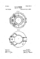
- Fig. 2 is a section on the line 1-2, Fig. 1.
- Fig. 3 is a section on the line 34, Fig. 1; and
- Fig.4, is a detached perspective View of the crab or flue section.
- furnace shown in the accompanying drawings is what is termed a portable heater, but it will be understood that my invention can be applied to brick set heaters as well.
- A is the casing
- B the fire pot section
- D the flue section mounted upon the fire pot section, and mounted upon this flue section are the drums a,a' and 0?, having suitable capsband b, so that the space 0 within the inner drum 0, and the space 0' between the drums at and a connect directly with the combustion chamber dot the flue section, while the space ebetween the drums at and a and the space 6 between the drum a and the casing A are air spaces for the passage of the air to be heated.
- the fire door opening (1 is provided with a suitable door (P.
- This fire door opening communicates with the space 0 through an opening (1 in the top plate D of the flue section.
- On each side of this fire door opening d are extensions D in which are formed fines or passages f communicating with the combustion chamber (1, and in the top plate D are openings f which form a communication between the said flues f and the space 0.
- the smoke fiue g is formed in the rear of the flue section G, and can be made to communicate directly with the combustion chamber 61 on operating a damper g, as clearly shown in Fig. 1, by turning the handle 9
- This damper is only turned down when the fire is being made or when it is wished to reduce considerably, the heat of the furnace, as the products of combustion will then pass directly out through the smoke flue, but when the damper is turned up all communication with the passage at the rear of the furnace is cut off except through the front flues f and d.
- the top plate D has an opening d at the rear, which communicates with the d no 9 formed in a tubular section mounted between the top plate and the flue section. This passage communicates with the smoke flue g.
- the flue section D is preferably made of cast metal, the extensions D being part of the structure, and are so formed that they receive the greater proportion of the products of combustion which is' naturally carried away from the fire door, so that when the said door is opened there will not be an escape of gas; at the same time the advantage of a complete circulation is obtained.
- the flue section D has a bottom plate D and bolts extend from the top and bottom plate tying the structure together.
Landscapes
- Engineering & Computer Science (AREA)
- Physics & Mathematics (AREA)
- Thermal Sciences (AREA)
- Chemical & Material Sciences (AREA)
- Combustion & Propulsion (AREA)
- Mechanical Engineering (AREA)
- General Engineering & Computer Science (AREA)
- Incineration Of Waste (AREA)
Description
(No Model.) 2 Sheets-Sheet 1.
W. P. WINNER.
HEATING FURNACE. No. 501,034. Patented July 4, 1893.
q FIG/J; L 5' v e e J1 4 c c g; c
a 4 I I a, h
1) 9* 3 7, Z7 gz T Invader wdllianvf. Winner 5 his ofltbor'wqyd momma. 2 Sheet,a-'-Sheet 2.
'W. P. WINNER; HEATING'FURNAGB.
Patented July 4, 1893.
' FIG-.3.
by luvs fitter-megs ww v UNITED STATES PATE T; OFFICE.
WILLIAM P. WINNER, OF QUAKERTOWN, PENNSYLVANIA, ASSIGNOR TO HIMSELF, WILLIAM P. ROBERTS, FRANK OAVANAUGH, OLIVER R. SOHEETZ, AND CHARLES A- KLUMP, OF SAME PLACE.
HEATING-FURNACE.
SPECIFICATION forming part of Letters Patent No. 501,034, dated July 4, 1893.
Application filed March 27, 1893- Serial No. 467.770. (No model.)
To all whom it may concern:
Be it known that I, WILLIAM P. WINNER, a
citizen of the United States, and a residentv of Quakertown, Bucks county, Pennsylvania, have invented certain Improvements in Heating-Furnaces, of which the following is aspecification.
The object of my invention is to so construct a hot air heating furnace that the products of combustion will pass away from the fire pot toward the front of the furnace and to the smoke flue in a circuitous path, heating the air more thoroughly than in the old method of allowing the products of combustion to pass away from the combustion chamber at the rear.
In the accompanying drawings :Figure 1, is a View in elevation, partly in section, illustrating my improved hot air furnace. Fig. 2, is a section on the line 1-2, Fig. 1. Fig. 3, is a section on the line 34, Fig. 1; and Fig.4, is a detached perspective View of the crab or flue section.
The furnace shown in the accompanying drawings is what is termed a portable heater, but it will be understood that my invention can be applied to brick set heaters as well.
A is the casing, B the fire pot section, D the flue section mounted upon the fire pot section, and mounted upon this flue section are the drums a,a' and 0?, having suitable capsband b, so that the space 0 within the inner drum 0, and the space 0' between the drums at and a connect directly with the combustion chamber dot the flue section, while the space ebetween the drums at and a and the space 6 between the drum a and the casing A are air spaces for the passage of the air to be heated.
The fire door opening (1 is provided with a suitable door (P. This fire door opening communicates with the space 0 through an opening (1 in the top plate D of the flue section. On each side of this fire door opening d are extensions D in which are formed fines or passages f communicating with the combustion chamber (1, and in the top plate D are openings f which form a communication between the said flues f and the space 0. Thus it will be seen that there are three openings into the space or passage 0' for the products of combustion, all at the front of the furnace, and the duo's f can be made of such asize that the products of combustion will readily pass into the space 0, so that the fire will not choke, and a better combustion will be effected.
The smoke fiue g is formed in the rear of the flue section G, and can be made to communicate directly with the combustion chamber 61 on operating a damper g, as clearly shown in Fig. 1, by turning the handle 9 This damper, however, is only turned down when the fire is being made or when it is wished to reduce considerably, the heat of the furnace, as the products of combustion will then pass directly out through the smoke flue, but when the damper is turned up all communication with the passage at the rear of the furnace is cut off except through the front flues f and d.
In order to prevent the too rapid passage of the products of combustion through the smoke flue, I mount within, the space 0 on each side of the furnace, a deflecting plate 0 so that the products of combustion will have to pass as shown by the arrows in Fig. 1, in
a circuitous path, thoroughly heating the drums at and a and consequently heating the air to a greater degree as it passes through thefurnace. The top plate D has an opening d at the rear, which communicates with the d no 9 formed in a tubular section mounted between the top plate and the flue section. This passage communicates with the smoke flue g.
The flue section D is preferably made of cast metal, the extensions D being part of the structure, and are so formed that they receive the greater proportion of the products of combustion which is' naturally carried away from the fire door, so that when the said door is opened there will not be an escape of gas; at the same time the advantage of a complete circulation is obtained. p
The flue section D has a bottom plate D and bolts extend from the top and bottom plate tying the structure together.
I claim as my invention- 1. The combination in a heating furnace, of
the tire pot, the flue section mounted above the fire pot, a smoke fine opening at the rear, a damper therefor, the fire door, extensions on each side of the fire door opening, fines formed in said extensions, drums mounted above the flue section and forming a passage for the products of combustion,substantially as described.
2. The combination in a heating furnace of the fire pot, the flue section mounted above the fire pot, fire door opening in the front of said section, extensions on each side of said opening, passages in said extensions communicating with the combustion chamber, drums mounted above the flue section forminga passage for the products of combustion and communicating only with the passages at the front of the furnace, deflecting plates in said passage, and a passage at the rear forming a communication between the space between the drums and the smoke flue, substantially as described.
3. The combination in a heating furnace, of the fire pot section and drums, a flue section mounted between the fire pot section and the drums, said flue section composed of three parts, a center piece in which the fines are formed, and top and bottom plates, with bolts securing the said parts together, each part having side extensions at the front forming the fines between the combustion chamber and the space between the drums, substantially as described.
In testimony whereof I have signed my name to this specification in the presence of two subscribing witnesses.
WILLIAM P. WINNER.
Witnesses:
WILLIAM D. CONNER, JOSEPH H. KLEIN.
Publications (1)
| Publication Number | Publication Date |
|---|---|
| US501034A true US501034A (en) | 1893-07-04 |
Family
ID=2569869
Family Applications (1)
| Application Number | Title | Priority Date | Filing Date |
|---|---|---|---|
| US501034D Expired - Lifetime US501034A (en) | William p |
Country Status (1)
| Country | Link |
|---|---|
| US (1) | US501034A (en) |
Cited By (1)
| Publication number | Priority date | Publication date | Assignee | Title |
|---|---|---|---|---|
| US2554101A (en) * | 1948-02-18 | 1951-05-22 | Freeman Herbert George | Vertical water heater |
-
0
- US US501034D patent/US501034A/en not_active Expired - Lifetime
Cited By (1)
| Publication number | Priority date | Publication date | Assignee | Title |
|---|---|---|---|---|
| US2554101A (en) * | 1948-02-18 | 1951-05-22 | Freeman Herbert George | Vertical water heater |
Similar Documents
| Publication | Publication Date | Title |
|---|---|---|
| US501034A (en) | William p | |
| US644792A (en) | Heater. | |
| US556807A (en) | Water-heating fireplace | |
| US217723A (en) | Improvement in hot-air furnaces | |
| US515515A (en) | Stove or range | |
| US290316A (en) | burns | |
| US148668A (en) | Improvement in heating-stoves | |
| US309495A (en) | Hot-air furnace | |
| US722414A (en) | Gas-range. | |
| US1321098A (en) | Heating-furnace | |
| US7143A (en) | Heating-furnace | |
| US746939A (en) | Heating stove or furnace. | |
| US137727A (en) | Improvement in hot-air furnaces | |
| US470727A (en) | Heating apparatus | |
| US278567A (en) | Combined heater and oven | |
| US492207A (en) | Heater | |
| US708563A (en) | Hot-air furnace. | |
| US771420A (en) | Furnace. | |
| US698806A (en) | Heating-stove. | |
| US705422A (en) | Hot-air heater. | |
| US1387453A (en) | stove | |
| US382659A (en) | Hot-water boiler | |
| US477216A (en) | Cooking stove or range | |
| US255826A (en) | And edwaed a | |
| US812746A (en) | Cooking-range. |