US5003820A - Electronic speedometer for snow skis - Google Patents
Electronic speedometer for snow skis Download PDFInfo
- Publication number
- US5003820A US5003820A US07/527,934 US52793490A US5003820A US 5003820 A US5003820 A US 5003820A US 52793490 A US52793490 A US 52793490A US 5003820 A US5003820 A US 5003820A
- Authority
- US
- United States
- Prior art keywords
- speed
- moves
- air
- vehicle
- thermocouple
- Prior art date
- Legal status (The legal status is an assumption and is not a legal conclusion. Google has not performed a legal analysis and makes no representation as to the accuracy of the status listed.)
- Expired - Fee Related
Links
- 230000000694 effects Effects 0.000 abstract description 2
- 238000010276 construction Methods 0.000 abstract 1
- 239000000523 sample Substances 0.000 description 12
- 238000005259 measurement Methods 0.000 description 6
- 230000001681 protective effect Effects 0.000 description 4
- 238000005516 engineering process Methods 0.000 description 3
- 238000012986 modification Methods 0.000 description 3
- 230000004048 modification Effects 0.000 description 3
- 239000000853 adhesive Substances 0.000 description 2
- 230000001070 adhesive effect Effects 0.000 description 2
- 239000003990 capacitor Substances 0.000 description 2
- 229920003023 plastic Polymers 0.000 description 2
- 239000011435 rock Substances 0.000 description 2
- 230000008030 elimination Effects 0.000 description 1
- 238000003379 elimination reaction Methods 0.000 description 1
- 238000010438 heat treatment Methods 0.000 description 1
- 230000009191 jumping Effects 0.000 description 1
- 238000004519 manufacturing process Methods 0.000 description 1
- 229910001220 stainless steel Inorganic materials 0.000 description 1
- 239000010935 stainless steel Substances 0.000 description 1
Images
Classifications
-
- G—PHYSICS
- G01—MEASURING; TESTING
- G01P—MEASURING LINEAR OR ANGULAR SPEED, ACCELERATION, DECELERATION, OR SHOCK; INDICATING PRESENCE, ABSENCE, OR DIRECTION, OF MOVEMENT
- G01P5/00—Measuring speed of fluids, e.g. of air stream; Measuring speed of bodies relative to fluids, e.g. of ship, of aircraft
- G01P5/10—Measuring speed of fluids, e.g. of air stream; Measuring speed of bodies relative to fluids, e.g. of ship, of aircraft by measuring thermal variables
- G01P5/12—Measuring speed of fluids, e.g. of air stream; Measuring speed of bodies relative to fluids, e.g. of ship, of aircraft by measuring thermal variables using variation of resistance of a heated conductor
-
- G—PHYSICS
- G01—MEASURING; TESTING
- G01P—MEASURING LINEAR OR ANGULAR SPEED, ACCELERATION, DECELERATION, OR SHOCK; INDICATING PRESENCE, ABSENCE, OR DIRECTION, OF MOVEMENT
- G01P3/00—Measuring linear or angular speed; Measuring differences of linear or angular speeds
- G01P3/42—Devices characterised by the use of electric or magnetic means
- G01P3/50—Devices characterised by the use of electric or magnetic means for measuring linear speed
Definitions
- This invention relates to an electronic speedometer. More particularly, the invention relates to a device which, when placed on a ski, will measure the speed of the ski or skier moving through the air.
- the present invention is believed to be found in the general Class 73 entitled, "Measurement and Testing", and more specifically in Subclass 204. While certain prior art describes what is referred to as “hot wire” technology, such technology has not been applied to a ski for the purposes of measuring its speed.
- U.S. Pat. No. 4,546,650 to Cameron describes a microcomputer that calculates speed and distance of the skier.
- the device is mounted on the rear portion of the ski, behind the skier, and is designed to be read when the skier comes to to a complete stop, at which time the skier, using his pole, pushes the appropriate buttons on the device to read performance parameters such as his distance traveled, his top speed and his average speed.
- the disadvantage of such a device is that the skier reads the values "after the fact" or after he has completed his ski run. The skier really does not know at which point he attained his maximum speed.
- Another disadvantage of Cameron's design is the use of a toothed wheel which must stay in contact with the snow to take any of its readings.
- U.S. Pat. No. 4,694,694 to Vertical Inst. Inc. discloses a device marketed under trademark "SkiMeter". This device measures several performance parameters such as altitude changes and vertical speed measurements. The unit is clipped on the skier and is also designed to be read when the skier comes to a full stop. The operation of the device is based on atmospheric pressure inputs which, through electronic circuitry, computes altitude changes and vertical speeds, i.e. the rate of vertical descent or rate of altitude loss of a skier. The disadvantage of such measurements is that the skier's downhill speed is very different from his vertical descent speed. Moreover, the device does not give an instantaneous readout of downhill speed of a skier. Thus the present invention overcomes the disadvantages of the prior art devices, as will be explained in the following.
- Another object of the invention is to provide a device showing increased ability, especially for the beginner, to ski with more control, to turn more smoothly, and to negotiate the steepness of a run better, as indicated by his gradual increases of speed.
- the device would also enable the skier to instantaneously evaluate his performance over any type of terrain and slope inclination. He would be able to monitor his peak speed and relate it to which point on the slop he achieved that speed. He would also be able to evaluate which parts of a slope gave him more difficulty, as shown by the decrease of speed.
- Still another object of the invention is the provision of a device which is useful to a skier in downhill speed competition, in showing him if he were able to achieve the speeds necessary on different areas of a slop to be a viable competitor.
- a still further object of my invention is to provide a device adapted to be placed on the forward end of the ski in full view of the skier, with the unit's height level being well below that of the curved ski tip, thereby minimizing any drag effect in the airflow it may have.
- a device for measuring speed between a vehicle adapted to be attached to a human foot or feet and the air through which it moves comprising of: (a) a thermistor or a suitable wire, maintained at a higher than ambient temperature and exposed to the airflow through which said vehicle moves; (b) a thermocouple exposed to said airflow through which said vehicle moves; (c) a base on which said thermistor or wire and said thermocouple are mounted; (d) means on said base for supplying electrical current to said thermistor or wire and said thermocouple; (e) means on said base for reading, combining and converting signals obtained from said thermistor or wire and said thermocouple and a means for displaying said speed digitally.
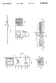
- FIG. 1 is a front view of the device according to the invention.
- FIG. 2 is a fragmentary cross-sectional view of the device, mounted on a ski, taken in the planes indicated by the broken line 2--2 in FIG. 3.
- FIG. 3 is a top plan view of the device.
- FIG. 4 is a detailed view of the probe with sensing elements, electrical connectors and a displaced view of a protective screen.
- FIG. 5 is a side view of the device itself mounted on a ski.
- the device of the invention works on the "hot wire” principle, but uses a precision thermistor in place of a wire mounted in the probe.
- the thermistor is maintained at a higher than ambient temperature and the current generated by the battery, used to maintain this temperature, is measured through a printed circuitry comprised of standard resisters, capacitors, amplifiers and various computer chips.
- the electronics within the device convert the reading, which varies with mass overflow, into equivalent velocity readings.
- the probe is fitted with a thermocouple to detect air temperature, the reading from which is used to automatically compensate the device for changes in air density with temperature.
- the device is contained in a two-part hollow plastic housing which comprises a top half I and a bottom half 2 as shown in FIG. 2.
- the two halves of the housing are held together with screws 3 as shown in FIG. 3.
- the top housing half 1, FIG. 2 contains an aperature 4 which permits viewing of the digital display 5 which is attached to the circuit board 6 thereunder.
- FIG. 2 also shows a transparent plastic lens 7 which is part of the top half 1 of the housing which provides a protective covering for the digital display 5.
- a stainless steel bar 8 is mounted through both housing halves 1 and 2 with screws 9. Its function is to protect the sensing elements in the probe housing 10 from damage during a fall.
- the top half 1 of the housing contains an opening that allows the probe 10 to have access to the electrical receptacle 11 which is attached to the circuit board 6 thereunder.
- FIG. 1 shows the probe housing 10 which contains the thermistor 13 and thermocouple 14.
- FIG. 4 shows a detailed view of the probe housing 10 with thermistor 13, thermocouple 14, electrical leads 22 and a protective screen 15 (shown displaced) which protects the thermistor 13 and thermocouple 14. Screen 15 is attached to housing 10 with a suitable adhesive. There is also a similar screen on the back side of housing 10 for protection thereof (not shown).
- FIG. 3 shows a conventional on-off switch 16 and zeroing dial 17.
- the dial 17 is used to compensate the unit 20 for any appreciable headwind that the user may want to nullify.
- FIG. 2 shows the unit mounted on a ski 18 with two suitable adhesive attachments 19, such as VELCRO.
- FIG. 2 also shows the main elements contained in the housing comprising of the printed circuit board 6, probe receptacle 11, digital display 5 and battery 21.
- Other support electronics such as conventional resistors, capacitors, amplifiers and computer chips are not shown in order to simplify consideration of the drawing.
- the entire unit 20 is typically placed on the front portion of the ski 18 as shown in FIG. 5.
- the probe 10 is placed in the unit 20 so that it receives the oncoming airflow from around a ski tip. This airflow is sensed by thermistor 13 and thermocouple 14 and is converted into a velocity from the electronics in the unit 20.
- the speed indicator of the invention provides a reliable means for determining instantaneous velocity measurements. It is lightweight, economical and easy to manufacture. The unit has no moving parts to wear out and the sleek design creates a very low drag through the air. The probe itself is replaceable in case of damage and can be easily and cheaply replaced by the user. The same unit, in its preferred embodiment, can easily be adapted to other uses, such as on a snowboard, a hanglider, a bicycle and motorized vehicles such as ultralight aircraft.
- An important advantage of my invention is that no part of it comes in contact with snow. Contact with the snow in any means is not necessary for its operation and since no part of it extends over the ski, it is not susceptible to damage from obstacles, such as rocks.
- Some of these modifications may include the device without the zero out dial. This would be useful if the device were used on a hanglider, in which case the user would need to know all headwind components.
- Another modification may include elimination of the thermistor and substituting a suitable wire of sufficient gauge to withstand the heating necessary to take accurate velocity measurements.
Landscapes
- Physics & Mathematics (AREA)
- General Physics & Mathematics (AREA)
- Engineering & Computer Science (AREA)
- Aviation & Aerospace Engineering (AREA)
- Measuring Temperature Or Quantity Of Heat (AREA)
Abstract
The electronic speedometer of this invention accurately calculates and digitally displays a skier's instantaneous speed. The device accomplishes this task by employing the "hot wire" principle using a thermistor and a thermocouple which are exposed to air stream through which the skis move. The device does not contain any moving parts and does not contact the snow or rely on snow contact for its operation. Since the construction of the device minimizes drag, its effect on a skier's performance is negligible. The device can easily be mounted and removed from a ski without the use of tools and without damaging the ski, thereby making it easily transferable to other surfaces, such as snowboards and hangliders.
Description
This invention relates to an electronic speedometer. More particularly, the invention relates to a device which, when placed on a ski, will measure the speed of the ski or skier moving through the air.
The present invention is believed to be found in the general Class 73 entitled, "Measurement and Testing", and more specifically in Subclass 204. While certain prior art describes what is referred to as "hot wire" technology, such technology has not been applied to a ski for the purposes of measuring its speed.
On the other hand, some patents disclose different technologies that have been applied to skis. For example, U.S. Pat. Nos. 3,505,878, 4,262,537, 4,546,650 and 4,694,694, describe various means for detecting speed of a skier.
U.S. Pat. No. 4,546,650 to Cameron describes a microcomputer that calculates speed and distance of the skier. The device is mounted on the rear portion of the ski, behind the skier, and is designed to be read when the skier comes to to a complete stop, at which time the skier, using his pole, pushes the appropriate buttons on the device to read performance parameters such as his distance traveled, his top speed and his average speed. The disadvantage of such a device is that the skier reads the values "after the fact" or after he has completed his ski run. The skier really does not know at which point he attained his maximum speed. Another disadvantage of Cameron's design is the use of a toothed wheel which must stay in contact with the snow to take any of its readings. Any time a skier loses contact with the snow, as in jumping or sometimes in turning, the wheel has no medium to cause it to spin and, therefore, it will not take very accurate measurements. Also, the wheel is exposed to different obstacles encountered on ski slopes, such as rocks and tree branches, which could easily damage it.
U.S. Pat. No. 4,694,694 to Vertical Inst. Inc. discloses a device marketed under trademark "SkiMeter". This device measures several performance parameters such as altitude changes and vertical speed measurements. The unit is clipped on the skier and is also designed to be read when the skier comes to a full stop. The operation of the device is based on atmospheric pressure inputs which, through electronic circuitry, computes altitude changes and vertical speeds, i.e. the rate of vertical descent or rate of altitude loss of a skier. The disadvantage of such measurements is that the skier's downhill speed is very different from his vertical descent speed. Moreover, the device does not give an instantaneous readout of downhill speed of a skier. Thus the present invention overcomes the disadvantages of the prior art devices, as will be explained in the following.
It is the principal object of this invention to provide an improved speedometer adapted to measure the skier's speed performance while going down a slope.
Another object of the invention is to provide a device showing increased ability, especially for the beginner, to ski with more control, to turn more smoothly, and to negotiate the steepness of a run better, as indicated by his gradual increases of speed. The device would also enable the skier to instantaneously evaluate his performance over any type of terrain and slope inclination. He would be able to monitor his peak speed and relate it to which point on the slop he achieved that speed. He would also be able to evaluate which parts of a slope gave him more difficulty, as shown by the decrease of speed.
Still another object of the invention is the provision of a device which is useful to a skier in downhill speed competition, in showing him if he were able to achieve the speeds necessary on different areas of a slop to be a viable competitor.
A still further object of my invention is to provide a device adapted to be placed on the forward end of the ski in full view of the skier, with the unit's height level being well below that of the curved ski tip, thereby minimizing any drag effect in the airflow it may have.
It is still a further object of this invention to provide a means of speed indication without contacting the snow in operation and without impeding the performance of any equipment on which the device is mounted for the purposes of speed indication.
It is still a further object of this invention to provide the device with a detachable probe containing the sensing elements to allow replacement of damaged elements.
It is still a further object of this invention to provide a device with a means to compensate for erroneous readings produced by headwinds.
It is still a further object of this invention to provide a means for displaying the speed digitally.
It is still a further object of this invention to provide a means of mounting the device on any desired movable surface, which allows easy removal from that surface without damaging that surface.
These and other objects of the invention will become more fully apparent from the following description and drawings.
In accordance with the invention described herein, there is provided a device for measuring speed between a vehicle adapted to be attached to a human foot or feet and the air through which it moves comprising of: (a) a thermistor or a suitable wire, maintained at a higher than ambient temperature and exposed to the airflow through which said vehicle moves; (b) a thermocouple exposed to said airflow through which said vehicle moves; (c) a base on which said thermistor or wire and said thermocouple are mounted; (d) means on said base for supplying electrical current to said thermistor or wire and said thermocouple; (e) means on said base for reading, combining and converting signals obtained from said thermistor or wire and said thermocouple and a means for displaying said speed digitally.
FIG. 1 is a front view of the device according to the invention.
FIG. 2 is a fragmentary cross-sectional view of the device, mounted on a ski, taken in the planes indicated by the broken line 2--2 in FIG. 3.
FIG. 3 is a top plan view of the device.
FIG. 4 is a detailed view of the probe with sensing elements, electrical connectors and a displaced view of a protective screen.
FIG. 5 is a side view of the device itself mounted on a ski.
The device of the invention works on the "hot wire" principle, but uses a precision thermistor in place of a wire mounted in the probe. The thermistor is maintained at a higher than ambient temperature and the current generated by the battery, used to maintain this temperature, is measured through a printed circuitry comprised of standard resisters, capacitors, amplifiers and various computer chips. The electronics within the device convert the reading, which varies with mass overflow, into equivalent velocity readings. The probe is fitted with a thermocouple to detect air temperature, the reading from which is used to automatically compensate the device for changes in air density with temperature.
Referring now to the drawings, the device is contained in a two-part hollow plastic housing which comprises a top half I and a bottom half 2 as shown in FIG. 2. The two halves of the housing are held together with screws 3 as shown in FIG. 3. The top housing half 1, FIG. 2, contains an aperature 4 which permits viewing of the digital display 5 which is attached to the circuit board 6 thereunder. FIG. 2 also shows a transparent plastic lens 7 which is part of the top half 1 of the housing which provides a protective covering for the digital display 5. A stainless steel bar 8 is mounted through both housing halves 1 and 2 with screws 9. Its function is to protect the sensing elements in the probe housing 10 from damage during a fall. The top half 1 of the housing contains an opening that allows the probe 10 to have access to the electrical receptacle 11 which is attached to the circuit board 6 thereunder.
FIG. 1 shows the probe housing 10 which contains the thermistor 13 and thermocouple 14. FIG. 4 shows a detailed view of the probe housing 10 with thermistor 13, thermocouple 14, electrical leads 22 and a protective screen 15 (shown displaced) which protects the thermistor 13 and thermocouple 14. Screen 15 is attached to housing 10 with a suitable adhesive. There is also a similar screen on the back side of housing 10 for protection thereof (not shown).
FIG. 3 shows a conventional on-off switch 16 and zeroing dial 17. The dial 17 is used to compensate the unit 20 for any appreciable headwind that the user may want to nullify.
FIG. 2 shows the unit mounted on a ski 18 with two suitable adhesive attachments 19, such as VELCRO. FIG. 2 also shows the main elements contained in the housing comprising of the printed circuit board 6, probe receptacle 11, digital display 5 and battery 21. Other support electronics such as conventional resistors, capacitors, amplifiers and computer chips are not shown in order to simplify consideration of the drawing.
The entire unit 20 is typically placed on the front portion of the ski 18 as shown in FIG. 5. Referring back to FIG. 1, the probe 10 is placed in the unit 20 so that it receives the oncoming airflow from around a ski tip. This airflow is sensed by thermistor 13 and thermocouple 14 and is converted into a velocity from the electronics in the unit 20.
It will be apparent from the foregoing description that the speed indicator of the invention provides a reliable means for determining instantaneous velocity measurements. It is lightweight, economical and easy to manufacture. The unit has no moving parts to wear out and the sleek design creates a very low drag through the air. The probe itself is replaceable in case of damage and can be easily and cheaply replaced by the user. The same unit, in its preferred embodiment, can easily be adapted to other uses, such as on a snowboard, a hanglider, a bicycle and motorized vehicles such as ultralight aircraft.
An important advantage of my invention is that no part of it comes in contact with snow. Contact with the snow in any means is not necessary for its operation and since no part of it extends over the ski, it is not susceptible to damage from obstacles, such as rocks.
While the above description contains many specific elements, these should not be construed as limitations on the scope of the invention but rather as the preferred embodiment. Many other variations are possible, depending on the sport or other uses it may have.
Some of these modifications may include the device without the zero out dial. This would be useful if the device were used on a hanglider, in which case the user would need to know all headwind components.
Another modification may include elimination of the thermistor and substituting a suitable wire of sufficient gauge to withstand the heating necessary to take accurate velocity measurements.
Other modifications may include eliminating the protective bar or relocating the position of the probe somewhere on the unit.
Accordingly, the scope of the invention should not be determined by the embodiment illustrated, but by the appended claims which follow.
Claims (15)
1. A device for measuring speed between a vehicle adapted to be attached to a human foot or feet and the air through which said vehicle moves, said device comprising of:
(a) a thermistor maintained at a higher than ambient temperature and exposed to the airflow through which said vehicle moves;
(b) a thermocouple exposed to said airflow through which said vehicle moves;
(c) a base on which said thermistor and said thermocouple are mounted;
(d) means on said base for supplying electrical current to said thermistor and said thermocouple;
(e) means on said base for reading, combining and converting signals obtained from said thermistor and said thermocouple to a speed reading;
(f) and means for displaying said speed reading digitally.
2. A device according to claim 1 wherein said device measures speed between a sliding wheelless vehicle and the air through which it moves.
3. A device according to claim 1 wherein said device measures speed between a wheeled vehicle and the air through which it moves.
4. A device according to claim 1 wherein said device measures speed between a motorized vehicle adapted for flight and the air through which it moves.
5. A device according to claim 1 wherein said device measures speed between a non-motorized vehicle adapted for flight and the air through which it moves.
6. A device according to claim 1 wherein said device measures speed between a snow ski and the air through which it moves.
7. A device according to claim 1, further including a circuit mounted on said base which allows a zeroing of said speed reading to compensate for erroneous readings.
8. A device according to claim 7, further including a means to said base for controlling said circuit.
9. A device for measuring speed between a vehicle adapted to be attached to a human foot or feet and the air through which said vehicle moves, said device comprising of:
(a) a wire of sufficient gauge and material maintained at a higher than ambient temperature and exposed to the airflow through which said vehicle moves;
(b) a thermocouple exposed to said airflow through which said vehicle moves;
(c) a base on which said wire and said thermocouple are mounted;
(d) means on said base for supplying electrical current to said wire and said thermocouple;
(e) means on said base for reading, combining, and converting signals obtained from said wire and said thermocouple to a speed reading;
(f) and means for displaying said speed reading digitally.
10. A device according to claim 9 wherein said device measures speed between a sliding wheelless vehicle and the air through which it moves.
11. A device according to claim 9 wherein said device measures speed between a wheeled vehicle and the air through which it moves.
12. A device according to claim 9 wherein said device measures speed between a motorized vehicle adapted for flight and the air through which it moves.
13. A device according to claim 9 wherein said device measures speed between a non-motorized vehicle adapted for flight and the air through which it moves.
14. A device according to claim 9, further including a circuit mounted on said base which allows a zeroing of said speed reading to compensate for erroneous readings.
15. A device according to claim 14, further including a means to said base for controlling said circuit.
Priority Applications (1)
| Application Number | Priority Date | Filing Date | Title |
|---|---|---|---|
| US07/527,934 US5003820A (en) | 1990-05-24 | 1990-05-24 | Electronic speedometer for snow skis |
Applications Claiming Priority (1)
| Application Number | Priority Date | Filing Date | Title |
|---|---|---|---|
| US07/527,934 US5003820A (en) | 1990-05-24 | 1990-05-24 | Electronic speedometer for snow skis |
Publications (1)
| Publication Number | Publication Date |
|---|---|
| US5003820A true US5003820A (en) | 1991-04-02 |
Family
ID=24103568
Family Applications (1)
| Application Number | Title | Priority Date | Filing Date |
|---|---|---|---|
| US07/527,934 Expired - Fee Related US5003820A (en) | 1990-05-24 | 1990-05-24 | Electronic speedometer for snow skis |
Country Status (1)
| Country | Link |
|---|---|
| US (1) | US5003820A (en) |
Cited By (8)
| Publication number | Priority date | Publication date | Assignee | Title |
|---|---|---|---|---|
| US5838635A (en) * | 1994-11-14 | 1998-11-17 | Masreliez; Karl | Thin speed transducer sensor |
| DE19725904A1 (en) * | 1997-06-13 | 1998-12-17 | Hartmut Dr Zimmermann | Arrangement for detecting skier motion parameters |
| DE19817001A1 (en) * | 1998-04-17 | 1999-10-28 | Jochen Tuente | Ski and jogging computer |
| US6533296B1 (en) | 2001-05-18 | 2003-03-18 | Eric A. Farraday | Snow board system |
| WO2006131954A1 (en) * | 2005-06-08 | 2006-12-14 | Fulvio Milani | Portable device for speed measurement |
| US20100123777A1 (en) * | 2008-04-22 | 2010-05-20 | David James Stewart | System and method for monitoring jump velocity |
| US20100123593A1 (en) * | 2008-04-22 | 2010-05-20 | David James Stewart | System and method for monitoring a jump landing area |
| US8482417B2 (en) | 2008-11-17 | 2013-07-09 | David Stewart | System and method for network-based jump area monitoring |
Citations (7)
| Publication number | Priority date | Publication date | Assignee | Title |
|---|---|---|---|---|
| US3505878A (en) * | 1968-03-18 | 1970-04-14 | Edward W Moll | Speed and distance indicator for a ski device |
| US4352063A (en) * | 1981-05-08 | 1982-09-28 | Jones Peter W J | Self-calibrating speedometer/odometer |
| US4546650A (en) * | 1983-09-23 | 1985-10-15 | Cameron John F | Speed and distance calculator for skis |
| US4694694A (en) * | 1986-01-06 | 1987-09-22 | Vertical Instruments, Inc. | Solid state accumulating altimeter |
| US4860585A (en) * | 1988-01-04 | 1989-08-29 | Tuyn William W | Measuring and indicating device for a snow skier |
| US4867860A (en) * | 1985-12-23 | 1989-09-19 | Hoffmann-La Roche Inc. | Method of manufacturing ion-selective electrodes for analyzing selected ions in solution |
| US4911005A (en) * | 1988-09-09 | 1990-03-27 | The John J. Heyn Co., Inc. | Velocity-measuring device |
-
1990
- 1990-05-24 US US07/527,934 patent/US5003820A/en not_active Expired - Fee Related
Patent Citations (7)
| Publication number | Priority date | Publication date | Assignee | Title |
|---|---|---|---|---|
| US3505878A (en) * | 1968-03-18 | 1970-04-14 | Edward W Moll | Speed and distance indicator for a ski device |
| US4352063A (en) * | 1981-05-08 | 1982-09-28 | Jones Peter W J | Self-calibrating speedometer/odometer |
| US4546650A (en) * | 1983-09-23 | 1985-10-15 | Cameron John F | Speed and distance calculator for skis |
| US4867860A (en) * | 1985-12-23 | 1989-09-19 | Hoffmann-La Roche Inc. | Method of manufacturing ion-selective electrodes for analyzing selected ions in solution |
| US4694694A (en) * | 1986-01-06 | 1987-09-22 | Vertical Instruments, Inc. | Solid state accumulating altimeter |
| US4860585A (en) * | 1988-01-04 | 1989-08-29 | Tuyn William W | Measuring and indicating device for a snow skier |
| US4911005A (en) * | 1988-09-09 | 1990-03-27 | The John J. Heyn Co., Inc. | Velocity-measuring device |
Cited By (12)
| Publication number | Priority date | Publication date | Assignee | Title |
|---|---|---|---|---|
| US5838635A (en) * | 1994-11-14 | 1998-11-17 | Masreliez; Karl | Thin speed transducer sensor |
| DE19725904A1 (en) * | 1997-06-13 | 1998-12-17 | Hartmut Dr Zimmermann | Arrangement for detecting skier motion parameters |
| DE19725904C2 (en) * | 1997-06-13 | 1999-05-27 | Hartmut Dr Zimmermann | Device for recording movement parameters when skiing |
| DE19817001A1 (en) * | 1998-04-17 | 1999-10-28 | Jochen Tuente | Ski and jogging computer |
| DE19817001C2 (en) * | 1998-04-17 | 2000-10-05 | Jochen Tuente | Measuring device for data acquisition on wheelless means of transportation |
| US6533296B1 (en) | 2001-05-18 | 2003-03-18 | Eric A. Farraday | Snow board system |
| WO2006131954A1 (en) * | 2005-06-08 | 2006-12-14 | Fulvio Milani | Portable device for speed measurement |
| US20100123777A1 (en) * | 2008-04-22 | 2010-05-20 | David James Stewart | System and method for monitoring jump velocity |
| US20100123593A1 (en) * | 2008-04-22 | 2010-05-20 | David James Stewart | System and method for monitoring a jump landing area |
| US8164472B2 (en) * | 2008-04-22 | 2012-04-24 | David James Stewart | System and method for monitoring a jump landing area |
| US8743197B2 (en) | 2008-04-22 | 2014-06-03 | David James Stewart | System and method for monitoring jump velocity |
| US8482417B2 (en) | 2008-11-17 | 2013-07-09 | David Stewart | System and method for network-based jump area monitoring |
Similar Documents
| Publication | Publication Date | Title |
|---|---|---|
| US6963818B2 (en) | Mobile speedometer system and associated methods | |
| US5960380A (en) | Apparatus and methods for determining loft time and speed | |
| US7949488B2 (en) | Movement monitoring systems and associated methods | |
| US6266623B1 (en) | Sport monitoring apparatus for determining loft time, speed, power absorbed and other factors such as height | |
| US4546650A (en) | Speed and distance calculator for skis | |
| US5844861A (en) | Athletic jump duration timing apparatus | |
| US6539336B1 (en) | Sport monitoring system for determining airtime, speed, power absorbed and other factors such as drop distance | |
| US6885971B2 (en) | Methods and systems for assessing athletic performance | |
| US5003820A (en) | Electronic speedometer for snow skis | |
| US20080306707A1 (en) | Impact Reporting Head Gear System And Method | |
| US8677639B2 (en) | Ski pole with inclinometer | |
| GB2137363A (en) | Speed indicating device for a ski or the like | |
| US5303954A (en) | Attachment to a ski stick | |
| US4776608A (en) | Ski binding release threshold display apparatus | |
| McKay | Problems of measuring and evaluating snowcover | |
| US4860585A (en) | Measuring and indicating device for a snow skier | |
| US4917399A (en) | Long distance ski binding | |
| US4977523A (en) | Apparatus for the measurement of snow quality | |
| WO2025133347A1 (en) | Angle measuring devices | |
| EP0159312A1 (en) | Apparatus for measuring distance or speed | |
| EP0594281A1 (en) | Attachment to a ski stick | |
| WO1990001707A1 (en) | Sports speedometer | |
| US20020107623A1 (en) | Apparatus for automatically ascertaining the setting for ski bindings | |
| DE3373630D1 (en) | Overstep recording device | |
| Klein et al. | An audio-modulated tethersonde for detailed micrometeorological soundings |
Legal Events
| Date | Code | Title | Description |
|---|---|---|---|
| CC | Certificate of correction | ||
| FPAY | Fee payment |
Year of fee payment: 4 |
|
| REMI | Maintenance fee reminder mailed | ||
| LAPS | Lapse for failure to pay maintenance fees | ||
| FP | Lapsed due to failure to pay maintenance fee |
Effective date: 19990402 |
|
| STCH | Information on status: patent discontinuation |
Free format text: PATENT EXPIRED DUE TO NONPAYMENT OF MAINTENANCE FEES UNDER 37 CFR 1.362 |