US5001663A - Programmable digital circuit for performing a matrix multiplication - Google Patents
Programmable digital circuit for performing a matrix multiplication Download PDFInfo
- Publication number
- US5001663A US5001663A US07/346,861 US34686189A US5001663A US 5001663 A US5001663 A US 5001663A US 34686189 A US34686189 A US 34686189A US 5001663 A US5001663 A US 5001663A
- Authority
- US
- United States
- Prior art keywords
- circuit
- input
- programmable
- signals
- matrix
- Prior art date
- Legal status (The legal status is an assumption and is not a legal conclusion. Google has not performed a legal analysis and makes no representation as to the accuracy of the status listed.)
- Expired - Lifetime
Links
Images
Classifications
-
- G—PHYSICS
- G06—COMPUTING OR CALCULATING; COUNTING
- G06F—ELECTRIC DIGITAL DATA PROCESSING
- G06F7/00—Methods or arrangements for processing data by operating upon the order or content of the data handled
- G06F7/38—Methods or arrangements for performing computations using exclusively denominational number representation, e.g. using binary, ternary, decimal representation
- G06F7/48—Methods or arrangements for performing computations using exclusively denominational number representation, e.g. using binary, ternary, decimal representation using non-contact-making devices, e.g. tube, solid state device; using unspecified devices
- G06F7/544—Methods or arrangements for performing computations using exclusively denominational number representation, e.g. using binary, ternary, decimal representation using non-contact-making devices, e.g. tube, solid state device; using unspecified devices for evaluating functions by calculation
- G06F7/5443—Sum of products
-
- G—PHYSICS
- G06—COMPUTING OR CALCULATING; COUNTING
- G06F—ELECTRIC DIGITAL DATA PROCESSING
- G06F5/00—Methods or arrangements for data conversion without changing the order or content of the data handled
- G06F5/01—Methods or arrangements for data conversion without changing the order or content of the data handled for shifting, e.g. justifying, scaling, normalising
-
- G—PHYSICS
- G06—COMPUTING OR CALCULATING; COUNTING
- G06F—ELECTRIC DIGITAL DATA PROCESSING
- G06F7/00—Methods or arrangements for processing data by operating upon the order or content of the data handled
- G06F7/38—Methods or arrangements for performing computations using exclusively denominational number representation, e.g. using binary, ternary, decimal representation
- G06F7/48—Methods or arrangements for performing computations using exclusively denominational number representation, e.g. using binary, ternary, decimal representation using non-contact-making devices, e.g. tube, solid state device; using unspecified devices
- G06F7/52—Multiplying; Dividing
- G06F7/523—Multiplying only
Definitions
- This invention pertains to the field of digital signal processing and, in particular, to the matrix multiplication of a plurality of digital signals by a coefficient matrix of the type used in color video signal processing.
- Correction matrices are useful in a variety of color video applications. For instance, a conversion matrix is used to convert red, green, and blue video signals into Y (luminance) and I, Q (chrominance) signals. A color correction matrix is used to correct the spectral sensitivities of a video camera for the chromaticities of the phosphor set of the particular display in use. Another use is with film-to-video conversion, a process in which a color correction matrix operates on the film scanning signals to correct the film colorimetry for video display.
- a conventional approach is to use an array of multipliers, say nine multipliers, to implement a 3 ⁇ 3 matrix. This uses a prohibitive amount of circuit area (on an integrated circuit).
- the multipliers can be replaced with ROM (read only memory) look-up tables. This still takes too much area.
- Another approach approximates the matrix coefficients by simple shifting operations, which can be implemented digitally by "hardwired" right (or left) shift connections between registers that provide a "binary" matrix coefficient series, such as 1/32, 1/16, 1/8, 1/4, 1/2, 1, 2, etc. Such poor coefficient accuracy can be improved by summing selected coefficients, but this requires many adders and many shifts. Once again, too much area is required.
- the invention departs from the prior art by mask-programming both the shifts and an arithmetic function in a simple, area-conserving configuration that lends itself to cascading, both for increased accuracy and ease of matrix implementation.
- the basis of the approach is the realization that by either adding or subtracting two "hardwired" shifted inputs, it is possible to obtain most of the desired matrix coefficients with a very small amount of circuitry. For instance, two input digital signals are separately multiplied or divided by programmable powers of two according to programmable bit shifts, yielding first and second intermediate signals. The intermediate signals are then arithmetrically combined according to a programmable arithmetic function, say addition or subtraction, to provide a product signal. By selecting the arithmetic function and defining the bit lengths of the shifts, the multiplier coefficient, or a component thereof, is established.
- This programmable circuit becomes a "building block” in which a plurality of like circuits are cascaded such that the output of one becomes the input to another for all but one such circuit that provides the matrix output signal. In such manner, the accuracy of each coefficient may be improved and at least one channel (row) of a matrix may be implemented.
- a multi-row matrix is obtained by driving several cascaded chains in parallel across a plurality of signal channels.
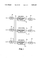
- FIG. 1 is a block diagram of a multi-channel video matrix circuit for performing a color correction
- FIG. 2 is a detailed diagram of the programmable matrix in the red channel shown in FIG. 1;
- FIG. 3 illustrates one of the programmable circuit blocks shown in FIG. 2.
- FIG. 1 a typical video matrix application is shown in which the matrix coefficients correct the spectral sensitivities of a video camera for the chromaticities of a particular phosphor display.
- the matrix is implemented in separate red, green and blue channels, as shown.
- a set of input signals R' i , G' i , and B' i from a video camera (not shown) are applied to separate ROM (read only memory) look-up tables 10, 12 and 14, which convert the input signals from the input mathematical space to a linear mathematical space. Since the preferred embodiment is used with logarithmic input signals, the tables 10, 12, and 14 convert the respective input log signals to a set of linear signals R i , G i , and B i .
- a color correction matrix is implemented row-by-row across the separate channels by a programmable red channel matrix 16, a programmable green channel matrix 18, and a programmable blue channel matrix 20.
- the linear signals R i , G i , and B i are applied to each of the matrixes 16, 18, and 20 for multiplication by an array of coefficients a ij .
- the color correction matrix operation is shown in equation (1), ##EQU1## where R o , G o , and B o are the signals output from the respective matrix circuits 16, 18, and 20.
- the coefficients a ij depend on the color-mixture functions of the phosphors used in the television display and the spectral sensitivities of the three color signals from the video camera, which includes the optics and the sensor.
- the coefficients can be positive or negative. In general, negative off-diagonal coefficients increase the color saturation of the image. Since it is ordinarily desirable to keep the sum of the coefficients in a given row equal to one, the diagonal coefficient is made greater than one to offset the negative off-diagonal coefficients.
- the coefficients are selected as shown in equation (2) for improved color rendition and color saturation, ##EQU2## where the coefficients a ij are selected for color correction in relation to a SMPTE "C" phosphor display, that is, a phosphor characteristic established by the Society of Motion Picture and Television Engineers.
- Each matrix 16, 18, and 20 implements a respective row of the matrix multiplication. For this reason, all signals R i , G i , and B i are applied to each matrix 16, 18, and 20.
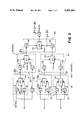
- the matrix operation uses constrained shift and add/subtract operations together with pipelining and parallelism as shown in FIG. 2 (for the red channel). This architecture avoids the use of multipliers.
- the coefficients are metal mask programmable between +/-1/32 and +/-2 at discrete (not necessarily equal) increments. The programmability allows the matrix circuit to be used with different image sensor spectral sensitivities or with different types of displays by changing a single mask.
- the matrix output signals R o , G o , and B o are then gamma-corrected in respective linear to gamma ROM look-up tables 22, 24, and 26, which provide suitable curve shape transformations to adjust the non-linear contrast relationship between the signal voltages at the input and the light values at the output of the system.
- the gamma-corrected output signals R' o , G' o , and B' o are suitably connected to a video display (not shown).
- the red matrix channel (as well as the green and blue matrix channels) includes metal mask programmable shift/add/subtract digital blocks, each basically identical and identified by the reference character 30.
- Each digital block 30 includes two registers 32 with mask programmable input shifts, each register basically identical except for the programmed shifts, and a mask programmable arithmetic unit 34.
- the registers 32 are mask programmed to provide the divisions as shown, i.e., a shift of one bit for 1/2, two bits for 1/4, three bits for 1/8, etc.
- the arithmetic unit 34 includes data inputs a and b, the input b capable of being negated by mask programming of a control input a/s thereof.
- the digital blocks 30 are cascaded whereby the output of one becomes the input to another, excepting for the last digital block 30, which provides the matrix output signal R o (i.e., R o 13/8R i 1/4G i 3/8B i ).
- R o matrix output signal
- the diagonal coefficient a 11 is calculated by the cascaded arrangement 36 of two blocks 30a and 30b. According to the arrangement 36, the red input signal R i is directed to both inputs of the upstream digital block 30a and one input of the following downstream block 30b. This is useful in providing coefficients of greater than one.
- the green and blue channel matrices are implemented with an architecture identical to that shown in FIG.
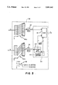
- FIG. 3 shows one of the digital blocks 30 in greater detail.
- the input bit resolution m and the output bit resolution n depend on whether the block 30 is an input, middle, or output block in the matrix channel, as shown in FIG. 2.
- FIG. 3 shows the internal construction of the block 30 and how the matrix coefficient "7/32" is mask programmed.
- the registers 32 include mask programmable input arrays identified as "hardwired" inputs 40a and 40b. Simple metal mask level alterations provide multiplication or division by a programmable power of two, that is, multiplication by 2 n for a number (n) of left shifts or division by 1/2 n for a number(n) of right shifts.
- the arithmetic unit 34 includes an adder 42 and an array 44 of n exclusive NOR gates, which together form a 2's complement adder.
- the adder 42 has one input a of n bits connected to the output of the "a" register 32 and a second input b of n bits connected to the array 44 of NOR gates, which are in turn connected to the output of the "b" register 32.
- the array 44 of NOR gates and the adder 42 receive a negating input ADD/SUB ("a/s" in FIG. 2) from a sign generator 46.
- the input 40a is "hardwired” by a simple metal mask level change to shift right two places to implement "x 1/4" while the input 40b is “hardwired” to shift right five places to implement "x 1/32".
- the most significant bits (MSB) thus bypassed in the shift are set to zero by "hardwiring” a digital "zero”.
- FIGS. 1-3 show how the programmable digital circuit is mask programmed for color correction in a video camera application.
- the programmable digital circuit could also be mask programmed as a conversion matrix to convert red, green and blue video signals into Y (luminance) and I, Q (chrominance) signals.
- the input look-up tables 10, 12, and 14 would be mask programmed for gamma correction and the output look-up tables 22, 24, and 26 would be mask programmed for a unity, or "straight line", curve transformation.
- the selection of suitable matrix coefficients for such a conversion is well within the ordinary skill of this art.
- Another application would be in a film to video conversion, such as for a telecine machine.
- log masking is required because the red, green, and blue video signals are being mapped through the approximately logarithmic characteristic curve of a film system to determine the red, green and blue recorded from the original scene, that is, the actual dye amounts formed in the image.
- the input look-up tables 10, 12, and 14 would be mask programmed for a "straight line" curve transformation, thus keeping the input signals R i , G i , and B i in log space.
- the logarithmically quantized signals are next matrixed with a 3 ⁇ 3 color correction matrix which has been mask programmed in order to properly correct the film colorimetry for video display. A suitable array of coefficients is well known in the art and thus not set forth here.
- the output look-up tables 22, 24, and 26 would then be mask programmed to convert the log signals into gamma corrected signals.
- Another application is in the conversion of the input signal from the color and tone scale of the instantaneously available video image to a color and tone scale matching a desired non-video output medium.
- the color and tone scale of the video image should match the appearance of the photographic print which will eventually be made.
- the linear signals R i , G i , and B i are multiplied by a 3 ⁇ 3 color correction matrix which has been mask programmed in order to best correct the spectral sensitivities of the camera so that the display colors are similar to the color reproduction of prints from film.
- a suitable set of coefficients can be selected or estimated from a knowledge of the required transformation, such knowledge being within the conventional teaching in this art.
- the output ROM look-up tables 22, 24, and 26 are mask programmed to convert from linear space to a "gamma corrected" space matched to the curve shape of the output medium (e.g., a photographic paper), so that the video display tone scale will match the print tone scale.
- a "gamma corrected" space matched to the curve shape of the output medium (e.g., a photographic paper), so that the video display tone scale will match the print tone scale.
Landscapes
- Engineering & Computer Science (AREA)
- Physics & Mathematics (AREA)
- General Physics & Mathematics (AREA)
- Theoretical Computer Science (AREA)
- Computational Mathematics (AREA)
- Mathematical Analysis (AREA)
- Mathematical Optimization (AREA)
- Pure & Applied Mathematics (AREA)
- General Engineering & Computer Science (AREA)
- Computing Systems (AREA)
- Processing Of Color Television Signals (AREA)
- Complex Calculations (AREA)
Abstract
Description
Claims (23)
Priority Applications (5)
| Application Number | Priority Date | Filing Date | Title |
|---|---|---|---|
| US07/346,861 US5001663A (en) | 1989-05-03 | 1989-05-03 | Programmable digital circuit for performing a matrix multiplication |
| PCT/US1990/002465 WO1990013866A1 (en) | 1989-05-03 | 1990-05-03 | A programmable digital circuit for performing a matrix multiplication |
| JP2507571A JPH03506088A (en) | 1989-05-03 | 1990-05-03 | Programmable digital circuit for performing matrix multiplication |
| DE69021164T DE69021164T2 (en) | 1989-05-03 | 1990-05-03 | PROGRAMMABLE DIGITAL CIRCUIT TO EXECUTE A MATRIX MULTIPLICATION. |
| EP90907539A EP0424506B1 (en) | 1989-05-03 | 1990-05-03 | A programmable digital circuit for performing a matrix multiplication |
Applications Claiming Priority (1)
| Application Number | Priority Date | Filing Date | Title |
|---|---|---|---|
| US07/346,861 US5001663A (en) | 1989-05-03 | 1989-05-03 | Programmable digital circuit for performing a matrix multiplication |
Publications (1)
| Publication Number | Publication Date |
|---|---|
| US5001663A true US5001663A (en) | 1991-03-19 |
Family
ID=23361330
Family Applications (1)
| Application Number | Title | Priority Date | Filing Date |
|---|---|---|---|
| US07/346,861 Expired - Lifetime US5001663A (en) | 1989-05-03 | 1989-05-03 | Programmable digital circuit for performing a matrix multiplication |
Country Status (5)
| Country | Link |
|---|---|
| US (1) | US5001663A (en) |
| EP (1) | EP0424506B1 (en) |
| JP (1) | JPH03506088A (en) |
| DE (1) | DE69021164T2 (en) |
| WO (1) | WO1990013866A1 (en) |
Cited By (20)
| Publication number | Priority date | Publication date | Assignee | Title |
|---|---|---|---|---|
| US5285271A (en) * | 1991-05-14 | 1994-02-08 | Hewlett-Packard Company | Digital color matrixing circuit |
| US5311459A (en) * | 1992-09-17 | 1994-05-10 | Eastman Kodak Company | Selectively configurable integrated circuit device for performing multiple digital signal processing functions |
| US5374956A (en) * | 1992-05-29 | 1994-12-20 | Eastman Kodak Company | Electronic imaging apparatus with dithered color filter array |
| US5402369A (en) * | 1993-07-06 | 1995-03-28 | The 3Do Company | Method and apparatus for digital multiplication based on sums and differences of finite sets of powers of two |
| US5410500A (en) * | 1992-02-21 | 1995-04-25 | Sony Corporation | Discrete cosine transform apparatus and inverse discrete cosine transform apparatus |
| US5420811A (en) * | 1992-08-26 | 1995-05-30 | Sony Corporation | Simple quick image processing apparatus for performing a discrete cosine transformation or an inverse discrete cosine transformation |
| US5553264A (en) * | 1994-06-24 | 1996-09-03 | Digital Equipment Corporation | Method and apparatus for efficient cache refilling by the use of forced cache misses |
| US5629882A (en) * | 1992-09-17 | 1997-05-13 | Sony Corporation | Discrete cosine transformation system and inverse discrete cosine transformation system, having simple structure and operable at high speed |
| US5668596A (en) * | 1996-02-29 | 1997-09-16 | Eastman Kodak Company | Digital imaging device optimized for color performance |
| US5826098A (en) * | 1995-05-29 | 1998-10-20 | Sharp Kabushiki Kaisha | Data processing system which converts received data packet into extended packet with prescribed field for accumulation process |
| US5933361A (en) * | 1992-11-13 | 1999-08-03 | Sony Corporation | Method of and apparatus for multiplying matrix data |
| US5971852A (en) * | 1994-06-20 | 1999-10-26 | Kabushiki Kaisha Sega Enterprises | Image processing method and apparatus |
| US6006246A (en) * | 1992-11-13 | 1999-12-21 | Sony Corporation | Method of and apparatus for multiplying matrix data |
| US6337923B1 (en) | 1998-10-15 | 2002-01-08 | Electronics And Telecommunications Research Institute | Color correction apparatus for minimizing metamerism of color scanner and method therefor |
| EP1220087A1 (en) * | 2000-12-28 | 2002-07-03 | Siemens Aktiengesellschaft | Apparatus for multiplication and/or filtering with constant integer values |
| US20030081832A1 (en) * | 2001-10-18 | 2003-05-01 | Shinichi Arazaki | Color conversion method, color conversion apparatus, color conversion matrix generation method and color conversion matrix generation program |
| WO2004030370A1 (en) * | 2002-09-11 | 2004-04-08 | Thomson Licensing S.A. | Device for adjusting colour video signals |
| US6749509B1 (en) * | 1994-06-20 | 2004-06-15 | Sega Corporation | Image processing method and apparatus |
| US6864915B1 (en) * | 2000-10-27 | 2005-03-08 | Eastman Kodak Company | Method and apparatus for production of an image captured by an electronic motion camera/sensor that emulates the attributes/exposure content produced by a motion camera film system |
| FR2895105A1 (en) * | 2005-12-20 | 2007-06-22 | St Microelectronics Sa | PROCESS FOR DIVIDING A NUMBER BY A FRACTION HAVING IN THE NUMERATOR A NUMBER IN THE FORM OF A POWER OF 2 |
Families Citing this family (4)
| Publication number | Priority date | Publication date | Assignee | Title |
|---|---|---|---|---|
| JPH04102170A (en) * | 1990-08-21 | 1992-04-03 | Fujitsu Ltd | Device and method for calculating matrix, and adaptive device |
| JPH05224891A (en) * | 1992-02-14 | 1993-09-03 | Sanyo Electric Co Ltd | Arithmetic circuit |
| US9384168B2 (en) | 2013-06-11 | 2016-07-05 | Analog Devices Global | Vector matrix product accelerator for microprocessor integration |
| US20160034421A1 (en) * | 2014-08-01 | 2016-02-04 | Infineon Technologies Ag | Digital pre-distortion and post-distortion based on segmentwise piecewise polynomial approximation |
Citations (7)
| Publication number | Priority date | Publication date | Assignee | Title |
|---|---|---|---|---|
| US3919535A (en) * | 1974-08-21 | 1975-11-11 | Singer Co | Multiple addend adder and multiplier |
| US4118785A (en) * | 1973-10-08 | 1978-10-03 | Nippon Telegraph And Telephone Public Corporation | Method and apparatus for digital attenuation by pattern shifting |
| US4455611A (en) * | 1981-05-11 | 1984-06-19 | Rca Corporation | Multiplier for multiplying n-bit number by quotient of an integer divided by an integer power of two |
| US4507676A (en) * | 1982-10-28 | 1985-03-26 | Rca Corporation | Digital matrixing system |
| US4568968A (en) * | 1982-07-03 | 1986-02-04 | Itt Industries, Inc. | Digital integrated circuit for the color matrix of a color-television set |
| US4589019A (en) * | 1983-04-22 | 1986-05-13 | Rca Corporation | Digital adder including counter coupled to individual bits of the input |
| US4700229A (en) * | 1985-07-09 | 1987-10-13 | U.S. Philips Corporation | Image enhancement circuit |
Family Cites Families (4)
| Publication number | Priority date | Publication date | Assignee | Title |
|---|---|---|---|---|
| US602362A (en) | 1898-04-12 | rowbotham | ||
| US741524A (en) | 1903-04-18 | 1903-10-13 | David P Miller | Panel-work or wainscoting. |
| US4041296A (en) * | 1975-12-03 | 1977-08-09 | International Business Machines Incorp. | High-speed digital multiply-by-device |
| US5545014A (en) | 1993-08-30 | 1996-08-13 | Coltec Industries Inc. | Variable displacement vane pump, component parts and method |
-
1989
- 1989-05-03 US US07/346,861 patent/US5001663A/en not_active Expired - Lifetime
-
1990
- 1990-05-03 EP EP90907539A patent/EP0424506B1/en not_active Expired - Lifetime
- 1990-05-03 WO PCT/US1990/002465 patent/WO1990013866A1/en not_active Ceased
- 1990-05-03 DE DE69021164T patent/DE69021164T2/en not_active Expired - Fee Related
- 1990-05-03 JP JP2507571A patent/JPH03506088A/en active Pending
Patent Citations (7)
| Publication number | Priority date | Publication date | Assignee | Title |
|---|---|---|---|---|
| US4118785A (en) * | 1973-10-08 | 1978-10-03 | Nippon Telegraph And Telephone Public Corporation | Method and apparatus for digital attenuation by pattern shifting |
| US3919535A (en) * | 1974-08-21 | 1975-11-11 | Singer Co | Multiple addend adder and multiplier |
| US4455611A (en) * | 1981-05-11 | 1984-06-19 | Rca Corporation | Multiplier for multiplying n-bit number by quotient of an integer divided by an integer power of two |
| US4568968A (en) * | 1982-07-03 | 1986-02-04 | Itt Industries, Inc. | Digital integrated circuit for the color matrix of a color-television set |
| US4507676A (en) * | 1982-10-28 | 1985-03-26 | Rca Corporation | Digital matrixing system |
| US4589019A (en) * | 1983-04-22 | 1986-05-13 | Rca Corporation | Digital adder including counter coupled to individual bits of the input |
| US4700229A (en) * | 1985-07-09 | 1987-10-13 | U.S. Philips Corporation | Image enhancement circuit |
Cited By (29)
| Publication number | Priority date | Publication date | Assignee | Title |
|---|---|---|---|---|
| US5285271A (en) * | 1991-05-14 | 1994-02-08 | Hewlett-Packard Company | Digital color matrixing circuit |
| US5410500A (en) * | 1992-02-21 | 1995-04-25 | Sony Corporation | Discrete cosine transform apparatus and inverse discrete cosine transform apparatus |
| US5374956A (en) * | 1992-05-29 | 1994-12-20 | Eastman Kodak Company | Electronic imaging apparatus with dithered color filter array |
| US5420811A (en) * | 1992-08-26 | 1995-05-30 | Sony Corporation | Simple quick image processing apparatus for performing a discrete cosine transformation or an inverse discrete cosine transformation |
| US5629882A (en) * | 1992-09-17 | 1997-05-13 | Sony Corporation | Discrete cosine transformation system and inverse discrete cosine transformation system, having simple structure and operable at high speed |
| US5311459A (en) * | 1992-09-17 | 1994-05-10 | Eastman Kodak Company | Selectively configurable integrated circuit device for performing multiple digital signal processing functions |
| US6006246A (en) * | 1992-11-13 | 1999-12-21 | Sony Corporation | Method of and apparatus for multiplying matrix data |
| US5933361A (en) * | 1992-11-13 | 1999-08-03 | Sony Corporation | Method of and apparatus for multiplying matrix data |
| US5402369A (en) * | 1993-07-06 | 1995-03-28 | The 3Do Company | Method and apparatus for digital multiplication based on sums and differences of finite sets of powers of two |
| US5971852A (en) * | 1994-06-20 | 1999-10-26 | Kabushiki Kaisha Sega Enterprises | Image processing method and apparatus |
| US6749509B1 (en) * | 1994-06-20 | 2004-06-15 | Sega Corporation | Image processing method and apparatus |
| US5553264A (en) * | 1994-06-24 | 1996-09-03 | Digital Equipment Corporation | Method and apparatus for efficient cache refilling by the use of forced cache misses |
| US5826098A (en) * | 1995-05-29 | 1998-10-20 | Sharp Kabushiki Kaisha | Data processing system which converts received data packet into extended packet with prescribed field for accumulation process |
| US5668596A (en) * | 1996-02-29 | 1997-09-16 | Eastman Kodak Company | Digital imaging device optimized for color performance |
| USRE39712E1 (en) * | 1996-02-29 | 2007-07-03 | Eastman Kodak Company | Digital imaging device optimized for color performance |
| US6337923B1 (en) | 1998-10-15 | 2002-01-08 | Electronics And Telecommunications Research Institute | Color correction apparatus for minimizing metamerism of color scanner and method therefor |
| US6864915B1 (en) * | 2000-10-27 | 2005-03-08 | Eastman Kodak Company | Method and apparatus for production of an image captured by an electronic motion camera/sensor that emulates the attributes/exposure content produced by a motion camera film system |
| EP1220087A1 (en) * | 2000-12-28 | 2002-07-03 | Siemens Aktiengesellschaft | Apparatus for multiplication and/or filtering with constant integer values |
| US7239744B2 (en) | 2001-10-18 | 2007-07-03 | Seiko Epson Corporation | Color conversion method, color conversion apparatus, color conversion matrix generation method and color conversion matrix generation program |
| US20030081832A1 (en) * | 2001-10-18 | 2003-05-01 | Shinichi Arazaki | Color conversion method, color conversion apparatus, color conversion matrix generation method and color conversion matrix generation program |
| WO2004030370A1 (en) * | 2002-09-11 | 2004-04-08 | Thomson Licensing S.A. | Device for adjusting colour video signals |
| GB2407446A (en) * | 2002-09-11 | 2005-04-27 | Thomson Licensing Sa | Device for adjusting colour video signals |
| GB2407446B (en) * | 2002-09-11 | 2005-12-28 | Thomson Licensing Sa | Arrangement for correcting colour video signals |
| US20060072172A1 (en) * | 2002-09-11 | 2006-04-06 | Andreas Loew | Device for adjusting colour video signals |
| US7903303B2 (en) | 2002-09-11 | 2011-03-08 | Gvbb Holdings S.A.R.L. | Device for adjusting color video signals |
| FR2895105A1 (en) * | 2005-12-20 | 2007-06-22 | St Microelectronics Sa | PROCESS FOR DIVIDING A NUMBER BY A FRACTION HAVING IN THE NUMERATOR A NUMBER IN THE FORM OF A POWER OF 2 |
| EP1801693A1 (en) * | 2005-12-20 | 2007-06-27 | Stmicroelectronics SA | Method for dividing a number by a denominator equal to the power of two |
| US20070146174A1 (en) * | 2005-12-20 | 2007-06-28 | Stmicroelectronics Sa | Method for dividing a number by a fraction having a number in the form of a power of 2 at the numerator |
| US7801940B2 (en) | 2005-12-20 | 2010-09-21 | Stmicroelectronics Sa | Method for dividing a number by a fraction having a number in the form of a power of 2 at the numerator |
Also Published As
| Publication number | Publication date |
|---|---|
| DE69021164D1 (en) | 1995-08-31 |
| EP0424506B1 (en) | 1995-07-26 |
| DE69021164T2 (en) | 1996-04-11 |
| EP0424506A1 (en) | 1991-05-02 |
| JPH03506088A (en) | 1991-12-26 |
| WO1990013866A1 (en) | 1990-11-15 |
Similar Documents
| Publication | Publication Date | Title |
|---|---|---|
| US5001663A (en) | Programmable digital circuit for performing a matrix multiplication | |
| US9483848B2 (en) | Image processing apparatus having a plurality of image processing blocks that are capable of real-time processing of an image signal | |
| US4992861A (en) | Color image reproduction apparatus having a digitally operated look-up table constructed by means of a least squares algorithm | |
| JPS63227293A (en) | Face sequential color image pickup device | |
| JPH03503951A (en) | Real-time digital processing device for generating full-resolution color signals from multicolor image sensors | |
| US6346969B1 (en) | Color filter array and its color interpolation apparatus | |
| JP3489118B2 (en) | Single-chip color camera and its color signal processing circuit | |
| JPS58106541A (en) | Color correcting apparatus and method of color image digitally displayed | |
| CA1201799A (en) | Apparatus for processing image signals | |
| US4329709A (en) | Solid-state color imaging device | |
| KR20000027364A (en) | Apparatus and method for regulating brightness of screen by using mean value of green pixel in image sensor | |
| JPH031693A (en) | Color correction device | |
| US5184214A (en) | Image output system | |
| US4910694A (en) | Method for approximating a value which is a nonlinear function of the linear average of pixel data | |
| JPS59111492A (en) | Digital signal processing circuit | |
| US6108038A (en) | Color video camera for generating a luminance signal with unattenuated harmonics | |
| US4527191A (en) | Digital signal processing circuit | |
| US6018599A (en) | Color image reading apparatus | |
| US5283670A (en) | Hardware implementation of an HDTV color corrector | |
| GB2238928A (en) | Image processing | |
| EP0081415A1 (en) | Matrixing apparatus for a colour television camera, and coder and camera comprising such an apparatus | |
| US7119925B2 (en) | Image processing, image reading apparatus and image processing method | |
| US6970208B1 (en) | Block move engine with gamma and color conversions | |
| US6788342B1 (en) | Color video camera for generating a luminance signal with unattenuated harmonics | |
| KR950005067B1 (en) | Color Reproducibility Correction Circuit of Digital Camera |
Legal Events
| Date | Code | Title | Description |
|---|---|---|---|
| AS | Assignment |
Owner name: EASTMAN KODAK COMPANY, A CORP. OF NJ, NEW YORK Free format text: ASSIGNMENT OF ASSIGNORS INTEREST.;ASSIGNORS:PARULSKI, KENNETH A.;HIBBARD, ROBERT H.;D'LUNA, LIONEL J.;REEL/FRAME:005068/0782 Effective date: 19890503 |
|
| FEPP | Fee payment procedure |
Free format text: PAYOR NUMBER ASSIGNED (ORIGINAL EVENT CODE: ASPN); ENTITY STATUS OF PATENT OWNER: LARGE ENTITY |
|
| STCF | Information on status: patent grant |
Free format text: PATENTED CASE |
|
| FPAY | Fee payment |
Year of fee payment: 4 |
|
| FEPP | Fee payment procedure |
Free format text: PAYER NUMBER DE-ASSIGNED (ORIGINAL EVENT CODE: RMPN); ENTITY STATUS OF PATENT OWNER: LARGE ENTITY Free format text: PAYOR NUMBER ASSIGNED (ORIGINAL EVENT CODE: ASPN); ENTITY STATUS OF PATENT OWNER: LARGE ENTITY |
|
| FPAY | Fee payment |
Year of fee payment: 8 |
|
| FPAY | Fee payment |
Year of fee payment: 12 |