US5000065A - Jaw assembly for power tongs and like apparatus - Google Patents
Jaw assembly for power tongs and like apparatus Download PDFInfo
- Publication number
- US5000065A US5000065A US07/480,323 US48032390A US5000065A US 5000065 A US5000065 A US 5000065A US 48032390 A US48032390 A US 48032390A US 5000065 A US5000065 A US 5000065A
- Authority
- US
- United States
- Prior art keywords
- gripping
- line
- pipe
- contact
- jaw
- Prior art date
- Legal status (The legal status is an assumption and is not a legal conclusion. Google has not performed a legal analysis and makes no representation as to the accuracy of the status listed.)
- Expired - Lifetime
Links
- 238000005553 drilling Methods 0.000 description 4
- 238000010276 construction Methods 0.000 description 1
- 238000007796 conventional method Methods 0.000 description 1
- 230000007246 mechanism Effects 0.000 description 1
- 230000035515 penetration Effects 0.000 description 1
- XLYOFNOQVPJJNP-UHFFFAOYSA-N water Substances O XLYOFNOQVPJJNP-UHFFFAOYSA-N 0.000 description 1
Images


Classifications
-
- E—FIXED CONSTRUCTIONS
- E21—EARTH OR ROCK DRILLING; MINING
- E21B—EARTH OR ROCK DRILLING; OBTAINING OIL, GAS, WATER, SOLUBLE OR MELTABLE MATERIALS OR A SLURRY OF MINERALS FROM WELLS
- E21B19/00—Handling rods, casings, tubes or the like outside the borehole, e.g. in the derrick; Apparatus for feeding the rods or cables
- E21B19/16—Connecting or disconnecting pipe couplings or joints
- E21B19/161—Connecting or disconnecting pipe couplings or joints using a wrench or a spinner adapted to engage a circular section of pipe
- E21B19/164—Connecting or disconnecting pipe couplings or joints using a wrench or a spinner adapted to engage a circular section of pipe motor actuated
-
- Y—GENERAL TAGGING OF NEW TECHNOLOGICAL DEVELOPMENTS; GENERAL TAGGING OF CROSS-SECTIONAL TECHNOLOGIES SPANNING OVER SEVERAL SECTIONS OF THE IPC; TECHNICAL SUBJECTS COVERED BY FORMER USPC CROSS-REFERENCE ART COLLECTIONS [XRACs] AND DIGESTS
- Y10—TECHNICAL SUBJECTS COVERED BY FORMER USPC
- Y10T—TECHNICAL SUBJECTS COVERED BY FORMER US CLASSIFICATION
- Y10T279/00—Chucks or sockets
- Y10T279/17—Socket type
- Y10T279/17615—Obliquely guided reciprocating jaws
- Y10T279/17649—Threaded sleeve and body
Definitions
- This invention relates to apparatus which grip and rotate pipe and the like and, more particularly, to the components of such apparatus which make contact with the pipe or the like being gripped and rotated.
- power tongs may be open-headed, having a housing with a central opening and an outward-open passageway or throat which permit the tong to be positioned around a pipe.
- power tongs may be close-headed, having no outward-open passageway or throat, being designed to be lowered over a length of pipe into an operating of position.
- pipe griping means (often referred to as jaws) are caused to revolve around the aforesaid central opening, these jaws causing the pipe or axially elongated object being gripped thereby to axially rotate.
- tongs typically have three to five jaws.
- These jaws are rotatably located inside a rotary member (referred to as a rotor) which is gear or chain driven.
- the rotor is powered through a gear train from a hydraulic or air motor.
- the jaws are generally in contact with a drag band arrangement, whereas when the rotor and jaws are rotated, the drag band will create a drag on the jaws causing them to pivot around their pivot points making initial contact with the pipe O.D.
- the present invention overcomes the problems and shortcomings of the prior art by providing an assembly for gripping a pipe for rotation of said pipe upon application of torque to the assembly, said assembly being of the type having automatically operating means for exerting increasing gripping force as amount of torque applied to the assembly increases, said assembly further having novel means for overriding and limiting said automatic means for exerting increased gripping force upon application of torque thereto.
- Still yet another object of the present invention is to provide replaceable inserts which can be used with power tong jaws accepting such inserts, which inserts provide the advantages offered by the present invention.
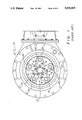
- FIG. 1 shows a relevant portion of a power tong having a prior art jaw assembly
- FIG. 2 shows a portion as in FIG. 1 but the tong partially shown therein has a jaw assembly according to the present invention
- FIG. 3 is a cross sectional view taken along line 3--3 of FIG. 2;
- FIG. 4 is a plan view of an integral jaw according to the present invention in contact with the outer surface of a pipe, this view having important angular relationships noted thereon;
- FIG. 5 is a view taken along line 5--5 in FIG. 4;
- FIG. 6 is a plan view of a jaw and insert according to the present invention.
- FIG. 7 is a view taken along line 7--7 of FIG. 6.
- Prior art jaw assembly 12 has five jaws 14, each having a replaceable insert 16 mounted thereon by known, conventional means.
- the replaceable inserts 16 are shown in FIG. 1 to be in contact with a pipe 18 that can be gripped and rotated by operation of power tong 10.
- Each jaw is pivotedly mounted at a pivot 20.
- the jaws are all located inside rotor 22 which is driven by conventional means (such as chain 23 shown in FIG.
- Jaw assembly 16 differs from prior art jaw assembly 12 in shape of the gripping portions thereof. Specifically, whereas prior art gripping portions inserts 16 in FIG. 1 have a completely convex shape (or more precisely, a constant "cam angle," a term that will be described in further detail below) the gripping portions of jaws 28 in FIG. 2 have also have a concave portion 30 (or portion manifesting an increasing cam angle), so that the complete gripping surface is in the form of an ogee.
- the increasing cam angle aspect of the present invention is shown therein in greater detail. It may be noted that the contact point between the pipe O.D. and the gripping portion of the illustrative jaw, point 32, form an angle ⁇ with relation to the centerline of the pipe 36 and the pivot point 38 of the jaw 28. Angle ⁇ is the herebefore mentioned cam angle. As those skilled in the art will appreciate, as a tangential force is applied in an opposite direction of the cam angle ⁇ , a radial force is transmitted to the pipe O.D. This radial force is generally large compared to the tangential force. For example, if the cam angle were 5° and a 1200# tangential force were applied, radial - force
- the jaw design shown therein has a ⁇ ° rotation for gripping pipe penetration, at which point those skilled in the art will appreciate that the reverse radius will become tangent to the pipe.
- the cam angle will start increasing very rapidly until the reverse radius is contacting the pipe O.D.
- the radial force at this position will be a maximum regardless of how much additional tangential force is applied.
- the increasing cam angle feature of the present invention limits radial force regardless of applied torque and, thus, is better than prior art devices which increase radial force proportionately to the tangential force as torque is applied. Through use of the present invention, the possibility of crushing or damaging drill pipe can be minimized, if not eliminated.
- FIG. 6 shows that the increasing cam angle feature of the present invention can be manifested in the form of a replaceable insert 28A which can be mounted to a jaw 28B capable of accepting such an insert.
- FIG. 3, 5 and 7 show cross sectional views of the certain configurations and elements discussed above, and are included to provide further details of construction for those skilled in the art.
- all elements constituting the present invention can be formed by conventional techniques known to those skilled in the art.
- those skilled in the art will appreciate the various views shown above are not necessarily to scale, most variations therefrom being in the interest of clarity. Still further, those skilled in the art will recognize that specific configurations described herein may be modified without departing from the scope and spirit of the present invention recited in the appended claims.
Landscapes
- Engineering & Computer Science (AREA)
- Life Sciences & Earth Sciences (AREA)
- Geology (AREA)
- Mining & Mineral Resources (AREA)
- Mechanical Engineering (AREA)
- Physics & Mathematics (AREA)
- Environmental & Geological Engineering (AREA)
- Fluid Mechanics (AREA)
- General Life Sciences & Earth Sciences (AREA)
- Geochemistry & Mineralogy (AREA)
- Earth Drilling (AREA)
Abstract
Description
Claims (5)
Priority Applications (1)
| Application Number | Priority Date | Filing Date | Title |
|---|---|---|---|
| US07/480,323 US5000065A (en) | 1987-09-08 | 1990-02-08 | Jaw assembly for power tongs and like apparatus |
Applications Claiming Priority (2)
| Application Number | Priority Date | Filing Date | Title |
|---|---|---|---|
| US9392187A | 1987-09-08 | 1987-09-08 | |
| US07/480,323 US5000065A (en) | 1987-09-08 | 1990-02-08 | Jaw assembly for power tongs and like apparatus |
Related Parent Applications (1)
| Application Number | Title | Priority Date | Filing Date |
|---|---|---|---|
| US9392187A Continuation | 1987-09-08 | 1987-09-08 |
Publications (1)
| Publication Number | Publication Date |
|---|---|
| US5000065A true US5000065A (en) | 1991-03-19 |
Family
ID=26788050
Family Applications (1)
| Application Number | Title | Priority Date | Filing Date |
|---|---|---|---|
| US07/480,323 Expired - Lifetime US5000065A (en) | 1987-09-08 | 1990-02-08 | Jaw assembly for power tongs and like apparatus |
Country Status (1)
| Country | Link |
|---|---|
| US (1) | US5000065A (en) |
Cited By (27)
| Publication number | Priority date | Publication date | Assignee | Title |
|---|---|---|---|---|
| US5823074A (en) * | 1995-12-14 | 1998-10-20 | Oil Country Manufacturing, Inc. | Open head foster-style back-up tong |
| US6206096B1 (en) | 1999-05-11 | 2001-03-27 | Jaroslav Belik | Apparatus and method for installing a pipe segment in a well pipe |
| US6598501B1 (en) * | 1999-01-28 | 2003-07-29 | Weatherford/Lamb, Inc. | Apparatus and a method for facilitating the connection of pipes |
| US20030221519A1 (en) * | 2000-03-14 | 2003-12-04 | Haugen David M. | Methods and apparatus for connecting tubulars while drilling |
| US6668684B2 (en) | 2000-03-14 | 2003-12-30 | Weatherford/Lamb, Inc. | Tong for wellbore operations |
| US20040045717A1 (en) * | 2002-09-05 | 2004-03-11 | Haugen David M. | Method and apparatus for reforming tubular connections |
| US20040049905A1 (en) * | 2002-09-12 | 2004-03-18 | Manfred Jansch | Automated pipe joining system |
| US6745646B1 (en) | 1999-07-29 | 2004-06-08 | Weatherford/Lamb, Inc. | Apparatus and method for facilitating the connection of pipes |
| US6814149B2 (en) | 1999-11-26 | 2004-11-09 | Weatherford/Lamb, Inc. | Apparatus and method for positioning a tubular relative to a tong |
| US20040237726A1 (en) * | 2002-02-12 | 2004-12-02 | Schulze Beckinghausen Joerg E. | Tong |
| US6829967B1 (en) * | 2003-08-01 | 2004-12-14 | Terry L. Kemp | Power tong tool |
| US20050061112A1 (en) * | 2003-09-19 | 2005-03-24 | Weatherford Lamb, Inc. | Adapter frame for a power frame |
| US20050076744A1 (en) * | 2003-10-08 | 2005-04-14 | Weatherford/Lamb, Inc. | Apparatus and methods for connecting tubulars |
| US20050188794A1 (en) * | 2002-02-12 | 2005-09-01 | Schulze-Beckinghausen Joerg E. | Gripping system for a tong |
| US7013759B1 (en) * | 2005-08-31 | 2006-03-21 | Access Oil Tools, Inc. | Apparatus for handling tubulars and method |
| US7028585B2 (en) | 1999-11-26 | 2006-04-18 | Weatherford/Lamb, Inc. | Wrenching tong |
| US7028586B2 (en) | 2000-02-25 | 2006-04-18 | Weatherford/Lamb, Inc. | Apparatus and method relating to tongs, continous circulation and to safety slips |
| US7090254B1 (en) | 1999-04-13 | 2006-08-15 | Bernd-Georg Pietras | Apparatus and method aligning tubulars |
| US20060248984A1 (en) * | 2005-05-03 | 2006-11-09 | Yaogen Ge | Spinner assembly for oilfield tubular connections |
| US20070044592A1 (en) * | 2005-08-31 | 2007-03-01 | Childress Lawrence E Ii | Apparatus for handling tubulars and method |
| US7188547B1 (en) | 2005-12-23 | 2007-03-13 | Varco I/P, Inc. | Tubular connect/disconnect apparatus |
| US20080087141A1 (en) * | 2006-10-13 | 2008-04-17 | Herman Myburgh | Adjustable, torque compensating powered pipe wrench |
| US20080098857A1 (en) * | 2006-10-13 | 2008-05-01 | Herman Myburgh | Powered adjustable pipe wrench |
| WO2009058023A1 (en) * | 2007-11-01 | 2009-05-07 | National Oilwell Norway As | A device for a power tong |
| US20090229423A1 (en) * | 2006-10-13 | 2009-09-17 | Herman Myburch | Powered adjustable pipe wrench |
| US7712523B2 (en) | 2000-04-17 | 2010-05-11 | Weatherford/Lamb, Inc. | Top drive casing system |
| US20140083255A1 (en) * | 2012-09-22 | 2014-03-27 | Kauffman Tools Llc | Universal self-adjusting, open-ended powered wrench |
Citations (4)
| Publication number | Priority date | Publication date | Assignee | Title |
|---|---|---|---|---|
| US1072142A (en) * | 1912-05-21 | 1913-09-02 | Frank P Miller | Chuck. |
| US2693365A (en) * | 1950-04-01 | 1954-11-02 | Fischer Ag Georg | Driver for lathes |
| US3413876A (en) * | 1968-12-03 | Arthur W Bencur | Power wrench for tightening studs in engine blocks and the like | |
| US3610640A (en) * | 1969-03-21 | 1971-10-05 | Curtis Mfg Co | Chuck assembly |
-
1990
- 1990-02-08 US US07/480,323 patent/US5000065A/en not_active Expired - Lifetime
Patent Citations (4)
| Publication number | Priority date | Publication date | Assignee | Title |
|---|---|---|---|---|
| US3413876A (en) * | 1968-12-03 | Arthur W Bencur | Power wrench for tightening studs in engine blocks and the like | |
| US1072142A (en) * | 1912-05-21 | 1913-09-02 | Frank P Miller | Chuck. |
| US2693365A (en) * | 1950-04-01 | 1954-11-02 | Fischer Ag Georg | Driver for lathes |
| US3610640A (en) * | 1969-03-21 | 1971-10-05 | Curtis Mfg Co | Chuck assembly |
Cited By (48)
| Publication number | Priority date | Publication date | Assignee | Title |
|---|---|---|---|---|
| US5823074A (en) * | 1995-12-14 | 1998-10-20 | Oil Country Manufacturing, Inc. | Open head foster-style back-up tong |
| US6598501B1 (en) * | 1999-01-28 | 2003-07-29 | Weatherford/Lamb, Inc. | Apparatus and a method for facilitating the connection of pipes |
| US7090254B1 (en) | 1999-04-13 | 2006-08-15 | Bernd-Georg Pietras | Apparatus and method aligning tubulars |
| US6206096B1 (en) | 1999-05-11 | 2001-03-27 | Jaroslav Belik | Apparatus and method for installing a pipe segment in a well pipe |
| US6745646B1 (en) | 1999-07-29 | 2004-06-08 | Weatherford/Lamb, Inc. | Apparatus and method for facilitating the connection of pipes |
| US7028585B2 (en) | 1999-11-26 | 2006-04-18 | Weatherford/Lamb, Inc. | Wrenching tong |
| US7861618B2 (en) | 1999-11-26 | 2011-01-04 | Weatherford/Lamb, Inc. | Wrenching tong |
| US20060179980A1 (en) * | 1999-11-26 | 2006-08-17 | Weatherford/Lamb, Inc. | Wrenching tong |
| US6814149B2 (en) | 1999-11-26 | 2004-11-09 | Weatherford/Lamb, Inc. | Apparatus and method for positioning a tubular relative to a tong |
| US7028586B2 (en) | 2000-02-25 | 2006-04-18 | Weatherford/Lamb, Inc. | Apparatus and method relating to tongs, continous circulation and to safety slips |
| US6668684B2 (en) | 2000-03-14 | 2003-12-30 | Weatherford/Lamb, Inc. | Tong for wellbore operations |
| US7107875B2 (en) | 2000-03-14 | 2006-09-19 | Weatherford/Lamb, Inc. | Methods and apparatus for connecting tubulars while drilling |
| US20040154835A1 (en) * | 2000-03-14 | 2004-08-12 | Weatherford/Lamb, Inc. | Tong for wellbore operations |
| US20030221519A1 (en) * | 2000-03-14 | 2003-12-04 | Haugen David M. | Methods and apparatus for connecting tubulars while drilling |
| US7028787B2 (en) | 2000-03-14 | 2006-04-18 | Weatherford/Lamb, Inc. | Tong for wellbore operations |
| US7712523B2 (en) | 2000-04-17 | 2010-05-11 | Weatherford/Lamb, Inc. | Top drive casing system |
| US7918273B2 (en) | 2000-04-17 | 2011-04-05 | Weatherford/Lamb, Inc. | Top drive casing system |
| US20050188794A1 (en) * | 2002-02-12 | 2005-09-01 | Schulze-Beckinghausen Joerg E. | Gripping system for a tong |
| US7506564B2 (en) | 2002-02-12 | 2009-03-24 | Weatherford/Lamb, Inc. | Gripping system for a tong |
| US20040237726A1 (en) * | 2002-02-12 | 2004-12-02 | Schulze Beckinghausen Joerg E. | Tong |
| US7281451B2 (en) | 2002-02-12 | 2007-10-16 | Weatherford/Lamb, Inc. | Tong |
| US7100697B2 (en) | 2002-09-05 | 2006-09-05 | Weatherford/Lamb, Inc. | Method and apparatus for reforming tubular connections |
| US20040045717A1 (en) * | 2002-09-05 | 2004-03-11 | Haugen David M. | Method and apparatus for reforming tubular connections |
| US7114235B2 (en) | 2002-09-12 | 2006-10-03 | Weatherford/Lamb, Inc. | Automated pipe joining system and method |
| US20040049905A1 (en) * | 2002-09-12 | 2004-03-18 | Manfred Jansch | Automated pipe joining system |
| US6829967B1 (en) * | 2003-08-01 | 2004-12-14 | Terry L. Kemp | Power tong tool |
| US20050061112A1 (en) * | 2003-09-19 | 2005-03-24 | Weatherford Lamb, Inc. | Adapter frame for a power frame |
| US7188548B2 (en) | 2003-09-19 | 2007-03-13 | Weatherford/Lamb, Inc. | Adapter frame for a power frame |
| US20050076744A1 (en) * | 2003-10-08 | 2005-04-14 | Weatherford/Lamb, Inc. | Apparatus and methods for connecting tubulars |
| US7707914B2 (en) | 2003-10-08 | 2010-05-04 | Weatherford/Lamb, Inc. | Apparatus and methods for connecting tubulars |
| US20060248984A1 (en) * | 2005-05-03 | 2006-11-09 | Yaogen Ge | Spinner assembly for oilfield tubular connections |
| US8667869B2 (en) | 2005-05-03 | 2014-03-11 | Yaogen Ge | Spinner assembly for oilfield tubular connections |
| US7013759B1 (en) * | 2005-08-31 | 2006-03-21 | Access Oil Tools, Inc. | Apparatus for handling tubulars and method |
| US20070044592A1 (en) * | 2005-08-31 | 2007-03-01 | Childress Lawrence E Ii | Apparatus for handling tubulars and method |
| US7313986B2 (en) | 2005-12-23 | 2008-01-01 | Varco I/P, Inc. | Tubular-drill bit connect/disconnect apparatus |
| US20070193417A1 (en) * | 2005-12-23 | 2007-08-23 | West Neil E | Tubular-drill bit connect/disconnect apparatus |
| US7188547B1 (en) | 2005-12-23 | 2007-03-13 | Varco I/P, Inc. | Tubular connect/disconnect apparatus |
| US20080098857A1 (en) * | 2006-10-13 | 2008-05-01 | Herman Myburgh | Powered adjustable pipe wrench |
| US7530294B2 (en) | 2006-10-13 | 2009-05-12 | Herman Myburgh | Powered adjustable pipe wrench |
| US20090229423A1 (en) * | 2006-10-13 | 2009-09-17 | Herman Myburch | Powered adjustable pipe wrench |
| US20080087141A1 (en) * | 2006-10-13 | 2008-04-17 | Herman Myburgh | Adjustable, torque compensating powered pipe wrench |
| US8141459B2 (en) | 2006-10-13 | 2012-03-27 | Herman Myburgh | Powered adjustable pipe wrench |
| GB2466164A (en) * | 2007-11-01 | 2010-06-16 | Nat Oilwell Varco Norway As | A device for a power tong |
| GB2466164B (en) * | 2007-11-01 | 2011-11-30 | Nat Oilwell Varco Norway As | A device for a power tong |
| US20100263495A1 (en) * | 2007-11-01 | 2010-10-21 | National Oilwell Varco Norway As | Device for a Power Tong |
| WO2009058023A1 (en) * | 2007-11-01 | 2009-05-07 | National Oilwell Norway As | A device for a power tong |
| US20140083255A1 (en) * | 2012-09-22 | 2014-03-27 | Kauffman Tools Llc | Universal self-adjusting, open-ended powered wrench |
| US9616556B2 (en) * | 2012-09-22 | 2017-04-11 | Robert Gregory Kauffman | Universal self-adjusting, open-ended powered wrench |
Similar Documents
| Publication | Publication Date | Title |
|---|---|---|
| US5000065A (en) | Jaw assembly for power tongs and like apparatus | |
| US4372026A (en) | Method and apparatus for connecting and disconnecting tubular members | |
| US5044232A (en) | Active jaw for a power tong | |
| US4437363A (en) | Dual camming action jaw assembly and power tong | |
| JPS62236606A (en) | Cutting tool | |
| EP0652815B1 (en) | Adjustable gripping device | |
| US4104752A (en) | Multipurpose tool | |
| EP0009629A1 (en) | Keyless chuck | |
| US7637183B2 (en) | Method of using adjustable pivotal wrench | |
| US3651557A (en) | Oil seal puller | |
| US5546833A (en) | Screw drive tool joint wrench | |
| US4060014A (en) | Power tong | |
| JPS5837111B2 (en) | power tongs | |
| US4986146A (en) | Camming member for power tongs | |
| BR9900269A (en) | Mandrel to be used with a manual or motorized actuator that has a rotating drive shaft. | |
| KR100266819B1 (en) | Wrench apparatus | |
| US4350062A (en) | Power tong | |
| JPS58106092A (en) | Power tong and jaw apparatus | |
| US7237456B2 (en) | Power tong with reduced die markings | |
| US4381685A (en) | Pipe joint make-up and break-out tool | |
| US6868756B2 (en) | Device to extract broken fasteners embedded in a workpiece | |
| WO1998040182A1 (en) | Manual tightened chuck | |
| US4862572A (en) | Retaining ring tool | |
| EP0040231B1 (en) | Pipe wrench | |
| US5113726A (en) | Utility tool |
Legal Events
| Date | Code | Title | Description |
|---|---|---|---|
| AS | Assignment |
Owner name: MARTIN-DECKER, INC., A CORP. OF TX, TEXAS Free format text: ASSIGNMENT OF ASSIGNORS INTEREST.;ASSIGNOR:VARCO INTERNATIONAL, INC.;REEL/FRAME:005377/0260 Effective date: 19900522 Owner name: VARCO INTERNATIONAL, INC., A CORP. OF CA, CALIFOR Free format text: ASSIGNMENT OF ASSIGNORS INTEREST.;ASSIGNOR:COOPER INDUSTRIES, INC.;REEL/FRAME:005377/0241 Effective date: 19900522 |
|
| STCF | Information on status: patent grant |
Free format text: PATENTED CASE |
|
| AS | Assignment |
Owner name: VARCO INTERNATIONAL, INC. A CORP. OF CALIFORNIA, Free format text: ASSIGNMENT OF ASSIGNORS INTEREST.;ASSIGNOR:MARTIN-DECKER TOTCO, INC. A CORP. OF TEXAS;REEL/FRAME:005695/0081 Effective date: 19910423 |
|
| AS | Assignment |
Owner name: MARTIN-DECKER TOTCO, INC. Free format text: CHANGE OF NAME;ASSIGNOR:MARTIN-DECKER, INC.;REEL/FRAME:005829/0095 Effective date: 19910220 |
|
| FPAY | Fee payment |
Year of fee payment: 4 |
|
| FPAY | Fee payment |
Year of fee payment: 8 |
|
| REMI | Maintenance fee reminder mailed | ||
| FPAY | Fee payment |
Year of fee payment: 12 |
|
| SULP | Surcharge for late payment |
Year of fee payment: 11 |