US4989641A - Rotary selector valve - Google Patents
Rotary selector valve Download PDFInfo
- Publication number
- US4989641A US4989641A US07/420,026 US42002689A US4989641A US 4989641 A US4989641 A US 4989641A US 42002689 A US42002689 A US 42002689A US 4989641 A US4989641 A US 4989641A
- Authority
- US
- United States
- Prior art keywords
- seal
- shaft
- wheel
- selector
- ring
- Prior art date
- Legal status (The legal status is an assumption and is not a legal conclusion. Google has not performed a legal analysis and makes no representation as to the accuracy of the status listed.)
- Expired - Fee Related
Links
- 238000007789 sealing Methods 0.000 claims abstract description 6
- 239000012530 fluid Substances 0.000 claims description 19
- 230000000694 effects Effects 0.000 claims description 10
- 230000000295 complement effect Effects 0.000 claims description 6
- 239000000463 material Substances 0.000 claims description 5
- 238000012163 sequencing technique Methods 0.000 claims description 4
- 238000004891 communication Methods 0.000 claims description 3
- 230000003534 oscillatory effect Effects 0.000 claims 3
- 230000002093 peripheral effect Effects 0.000 claims 3
- 238000012360 testing method Methods 0.000 abstract description 16
- 230000007246 mechanism Effects 0.000 abstract description 11
- 239000004033 plastic Substances 0.000 description 6
- 241001125879 Gobio Species 0.000 description 2
- 229910000831 Steel Inorganic materials 0.000 description 2
- 230000006835 compression Effects 0.000 description 2
- 238000007906 compression Methods 0.000 description 2
- 230000003628 erosive effect Effects 0.000 description 2
- 239000010959 steel Substances 0.000 description 2
- 239000004677 Nylon Substances 0.000 description 1
- 230000004323 axial length Effects 0.000 description 1
- 239000004020 conductor Substances 0.000 description 1
- 238000010276 construction Methods 0.000 description 1
- 230000007797 corrosion Effects 0.000 description 1
- 238000005260 corrosion Methods 0.000 description 1
- 230000008878 coupling Effects 0.000 description 1
- 238000010168 coupling process Methods 0.000 description 1
- 238000005859 coupling reaction Methods 0.000 description 1
- 230000006866 deterioration Effects 0.000 description 1
- 238000004519 manufacturing process Methods 0.000 description 1
- 239000002184 metal Substances 0.000 description 1
- 239000000203 mixture Substances 0.000 description 1
- 229920001778 nylon Polymers 0.000 description 1
- 230000010355 oscillation Effects 0.000 description 1
- 239000002245 particle Substances 0.000 description 1
- 239000004576 sand Substances 0.000 description 1
Images


Classifications
-
- F—MECHANICAL ENGINEERING; LIGHTING; HEATING; WEAPONS; BLASTING
- F16—ENGINEERING ELEMENTS AND UNITS; GENERAL MEASURES FOR PRODUCING AND MAINTAINING EFFECTIVE FUNCTIONING OF MACHINES OR INSTALLATIONS; THERMAL INSULATION IN GENERAL
- F16K—VALVES; TAPS; COCKS; ACTUATING-FLOATS; DEVICES FOR VENTING OR AERATING
- F16K31/00—Actuating devices; Operating means; Releasing devices
- F16K31/44—Mechanical actuating means
- F16K31/52—Mechanical actuating means with crank, eccentric, or cam
- F16K31/524—Mechanical actuating means with crank, eccentric, or cam with a cam
- F16K31/52458—Mechanical actuating means with crank, eccentric, or cam with a cam comprising a tap or cock
- F16K31/52466—Mechanical actuating means with crank, eccentric, or cam with a cam comprising a tap or cock comprising a multiple-way tap or cock
-
- F—MECHANICAL ENGINEERING; LIGHTING; HEATING; WEAPONS; BLASTING
- F16—ENGINEERING ELEMENTS AND UNITS; GENERAL MEASURES FOR PRODUCING AND MAINTAINING EFFECTIVE FUNCTIONING OF MACHINES OR INSTALLATIONS; THERMAL INSULATION IN GENERAL
- F16K—VALVES; TAPS; COCKS; ACTUATING-FLOATS; DEVICES FOR VENTING OR AERATING
- F16K11/00—Multiple-way valves, e.g. mixing valves; Pipe fittings incorporating such valves
- F16K11/02—Multiple-way valves, e.g. mixing valves; Pipe fittings incorporating such valves with all movable sealing faces moving as one unit
- F16K11/08—Multiple-way valves, e.g. mixing valves; Pipe fittings incorporating such valves with all movable sealing faces moving as one unit comprising only taps or cocks
- F16K11/085—Multiple-way valves, e.g. mixing valves; Pipe fittings incorporating such valves with all movable sealing faces moving as one unit comprising only taps or cocks with cylindrical plug
-
- Y—GENERAL TAGGING OF NEW TECHNOLOGICAL DEVELOPMENTS; GENERAL TAGGING OF CROSS-SECTIONAL TECHNOLOGIES SPANNING OVER SEVERAL SECTIONS OF THE IPC; TECHNICAL SUBJECTS COVERED BY FORMER USPC CROSS-REFERENCE ART COLLECTIONS [XRACs] AND DIGESTS
- Y10—TECHNICAL SUBJECTS COVERED BY FORMER USPC
- Y10T—TECHNICAL SUBJECTS COVERED BY FORMER US CLASSIFICATION
- Y10T137/00—Fluid handling
- Y10T137/8593—Systems
- Y10T137/86493—Multi-way valve unit
- Y10T137/86501—Sequential distributor or collector type
Definitions
- the present invention relates to valves and, more particularly, to a multi-position rotary selector valve.
- Multi-port selector valves have been in use for many years in a variety of applications.
- such valves comprise a valve body having circularly spaced apart inlet ports each of which receives fluid from a well head.
- the valve body cover plate rotatably mounts one end of a trunnion whose lower end is rotatably mounted in a bottom portion of the valve body.
- the trunnion member contains an elbow passage having an inlet nozzle that can be turned into registration with a selected one of the inlet ports for conducting the selected well stream to a test outlet in the lower end of the valve body in communication with the opposite end of the elbow passage.
- the non-isolated fluid streams entering through the other inlet ports commingle in a common cavity of the valve body to be exhausted through a production outlet, also formed in the lower portion of valve body.
- the inlet nozzle to the elbow passage comprises a hard plastic sliding seal ring mounted on a shoulder of a steel seal backup ring which, in turn, is seated upon a wavy steel seal-energizing spring ring backed up by an adjusting nut threadedly engaged within the nozzle mouth.
- the seal ring free-floats inside the nozzle mouth and is pressed tightly against a machined cylindrical surface of the valve body by the spring ring.
- the hard seal slides against the valve body wall. If a grain of sand or other particle happens to lodge in this tight fit, the plastic seal is scratched and begins to leak. Internal valve corrosion also erodes the plastic seal.
- the backup nut In order to restore the seal, the backup nut must then be adjusted to compress the backup spring to further load the seal which, in turn, effects further erosion.
- the seal ring As the seal ring is tightly slidably engaged with the valve body wall while turning from one position to another, the seal may itself rotate relative to its supporting ring and assume a position of its convex sealing surface which is not matingly complementary to the configuration of the machined cylindrical inner surface of the valve body on which it is intended to seat.
- the prior art valve has been so prone to internal leakage that it has been customary to dedicate one of its inlet ports solely to sue as a test position in order to detect leakage and to gain access to the adjusting nut to further compress the backup spring.
- Such dedication of one of the inlet ports for use solely as a test position eliminates use of that port as a test site for another well and so increases equipment costs.
- the invention provides an improved multi-port selector valve which minimizes internal leakage and has a rotary nozzle member which can be positively indexed to a new test position and be rotated between inlet test ports by a small motor since there is no sliding friction between the nozzle inlet and the valve body.
- the invention also provides an internal valve mechanism or trunnion assembly which can be retrofitted to existing valve bodies without reworking of the bodies and their covers.
- a valve body is formed with an internal cylindrical machined surface having a plurality of equally usable circularly spaced apart inlet ports.
- An upper end of the valve body is conventionally closed by a cover plate that rotatably mounts an upper end portion of a inlet port selector means comprising a trunnion member having a lower end gudgeon rotatably seated within the lower end of the valve body.
- the trunnion member includes a side arm portion comprising the inlet nozzle to an elbow passage through the trunnion member, the lower end of the elbow passage communicating with a test cutlet port formed in the valve body.
- the remaining inlet ports induct fluids into the common valve cavity within the valve body to communicate with an outlet port also formed in the lower end of the valve body.
- the side arm inlet nozzle of the trunnion member contains a hollow seal support means comprising a reciprocably mounted seal piston integrally formed at its inner end with an eccentric mounting shaft.
- An outer end of the seal piston seats a seal mounting ring, preferably made of hard plastic material, having an endless groove of dovetail cross-sectional configuration formed in its outer face.
- the dovetail groove replaceably mounts an endless or circular seal ring that, in a relaxed state, protrudes beyond the outer end face of the mounting ring.
- the upper end portion of the trunnion member mounts actuating means to reciprocate the seal piston comprising a coaxial actuating shaft.
- the lower end of the shaft has an integrally formed eccentric pin to engage the sides of a transverse slot formed in the support shaft for the seal piston.
- Rotation of the actuating shaft effects limited reciprocation of the seal piston between extended and retracted positions thereof.
- the seal ring In the extended position of the seal piston, the seal ring is compressed into tight sealing engagement with the cylindrical inner surface of the valve body around a selected inlet port.
- the seal ring In the retracted position of the seal piston, the seal ring is retracted from contact with the valve body in order to be turntable to the next inlet port without sliding contact with the valve body.
- Sequencing and control means to effect phased reciprocation of the seal piston and rotation of the inlet nozzle are mounted in operative association with upper end portions of the trunnion member and the actuating shaft for the seal piston.
- the mechanism includes a drive shaft coaxially keyed to an input rotor.
- the input rotor comprises a sequencing cam on its upper face in operative association with a geneva wheel portion of the control means that is formed with a plurality of dwell notches spaced alternately with a plurality of radially disposed geneva wheel drive slots.
- the number of dwell notches and drive slots are equal to the number of inlet ports formed in the valve body.
- the cam of the input rotor is normally engaged with one of the dwell notches in the geneva wheel such that, upon rotation of the input rotor and cam through a predetermined arc the geneva wheel, which is drivingly coupled to the upper end of the trunnion member, maintains the nozzle of the trunnion in an indexed position in registration with one of the inlet ports.
- a geneva drive roller carried by the input rotor enters into driving engagement with a slot of the geneva wheel to rotate the nozzle forwardly through a predetermined arc into alignment with the next adjacent inlet port.
- the upper end portion of the actuating shaft coaxially mounts a sprocket wheel portion of the sequencing means that is drivingly coupled to the actuating shaft.
- the housing for the mechanism internally mounts a pivotal yoke in coplanar operative association with the sprocket.
- the free swingable end of a pair of lever arms of the yoke assembly mount a roller that is driving engageable with a selected one of a plurality of radially disposed asymmetrical slots formed in the sprocket.
- an elongate bar formed with a longitudinally extending slot, the bar being pivotal independently of the yoke.
- the yoke mounts a bridging plate which loosely contains a spring loaded fastener carried by the intermediate bar and that normally biases the bar towards the yoke.
- An outer end of the yoke mounts an adjustable stop whose inner end is engageable by an outer end of the bar such that, when the bar is pivoted in a retrograde direction toward the yoke, the yoke is unidirectionally driveably engaged thereby.
- the upper face of the cam of the input rotor mounts a crank pin roller that traverses the slot of the tar to effect phased oscillation of the bar and yoke during rotation of the input rotor.
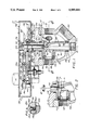
- FIG. 1 is a vertical, partly sectional view taken through the vertical axis of the rotary selector valve of the invention
- FIG. 1A is a partial sectional view of the area A of FIG. 1, on a larger scale, but showing different relative positions of certain parts;
- FIG. 2 is a partial sectional view like FIG. 1 but showing the seal piston of the nozzle of the selector valve in a retracted position;
- FIG. 3 is an exploded perspective view of internal components of the valve and its controller means
- FIGS. 4 and 5 are top plan views of the valve control mechanisms in two different relative positions of certain of their parts
- FIG. 6 is a transverse sectional view taken on the line 6--6 of FIG. 1;
- FIG. 7 is a view like FIG. 6 but showing the nozzle in a retracted position and angularly displaced from its position in FIG. 6;
- FIG. 8 is a partial bottom plan view of the control housing and motor housing.
- the rotary selector valve of this invention comprises a valve assembly, designated generally by the numeral 10, on top of which a controller mechanism, designated generally by the numeral 12, is mounted.
- the valve assembly 10 comprises a hollow body 14 defining a common valve cavity 16.
- the side wall of the body 14 is formed with a plurality of radially extending inlet ports 18, all of which have their axes in a common plane.
- the body 14 is formed with eight of the inlet ports 18.
- the valve body 14 could be formed with any desired practical number of inlet ports.
- each of the inlet ports 18 inducts a fluid from a different source into the common cavity 16 from whence the fluids, except for fluid from the particular source which it is desired to monitor, are exhausted from the valve body through a downwardly and sidewardly directed outlet port 20.
- valve body 14 is conventionally closed by a cover plate 24 that is held in position by a circular array of conventional threaded fastener means 26.
- the bottom face of the cover plate 24 may be formed with a circular boss 28 that is matingly received within the upper end of the valve body 14, the periphery of the boss 28 being formed with a circumferential groove for the reception of an 0-ring seal 30.
- the cover plate 24 is formed with a central circular opening 34 to rotatably seat an upper end stem portion 36 of a trunnion member, designated generally by the numeral 38.
- the stem portion 36 of the trunnion member extends upwardly beyond the cover plate 24 for operative association with the controller means 12, as will later appear.
- the hole 34 in cover plate 24 is formed with a spaced pair of recessed grooves for seating a felt seal ring 42 and a bushing 44 and, at its inner end, defines a shoulder for the reception of an 0-ring seal 46.
- the trunnion member 38 is an essentially T-shaped member having a lower end gudgeon portion 50, coaxially aligned with the upper end stem portion 36, and a side arm nozzle portion 52 extending at a right angle.
- the nozzle axis is co-planar with the axes of ports 18.
- the lower end portion 50 of the trunnion member is rotatably seated within a central circular cavity 54 of valve body 14 in coaxial alignment with a test outlet port 56 through the bottom of the valve body.
- the lower end portion 50 of the trunnion member is formed on its external surface with a recessed groove for the reception of an 0-ring seal 58 and with a lowermost shoulder to seat a bushing 60.
- the trunnion 38 is thus seated within the valve body 14 and cover 24 such that the sidearm 52 can be rotated into registration with a desired one of the inlet ports 18.
- the side arm portion 52 and lower end portion 50 of the trunnion member are hollow to define an elbow shaped passage 62 such that fluid inducted from one of the remote sources thereof through a selected inlet port 18 is exhausted from the valve body through the test port 56.
- the inner surface of body 14 is formed in the configuration of a smooth cylindrical surface 66. Accordingly, an outer end 68 of the side arm 52 of the rotary nozzle is formed with a complementary convex surface conforming to the locus defined by the intersection of a small cylinder with a larger cylinder at right angles thereto. As as shown in FIG. 6 and 7, there is preferably a slight clearance between the outer end 68 of the side arm 52 and the cylindrical surface 66 within the valve body, although a sliding clearance could be employed.
- a seal piston designated generally by the numeral 72, whose overall configuration is best seen in FIG. 3.
- the seal piston has a cylindrical body section 74 and its inner end is integrally formed with an offset shaft 76 of small diameter as compared to the diameter of the body section 74.
- the shaft 76 has a surface which has a point of tangency with the body section 74 such that a longitudinal trace of the external surface of body section 74 also constitutes a longitudinal trace of the shaft 76.
- a pocket or hole 78 is formed in a wall portion of the trunnion member 38 to matingly seat the shaft 76 for axial slidable reciprocation therein.
- Adjacent to the rear end of the shaft 76 is a recessed groove 80 for the reception of an 0-ring 82 in order to provide a fluid seal between the common cavity 16 of the valve body and elbow passage 62.
- the outer end of the seal piston 72 is machined to define a shoulder 86 on which a complementary seat 90 of a ring 88 is seated.
- the ring 88 is preferably made of an essentially hard synthetic plastic material such as nylon and is formed with an outer end face 92 with a convex nonplanar configuration matingly complementary to the cylindrical surface portion 66 of the valve body.
- a pair of fasteners 94 extend through diametrically opposed holes 96 extending axially through the body portion 74 of the seal piston to be threadedly engaged with tapped bores (not shown) in the rear face of the ring 88 to hold the ring in place on the seal piston as it undergoes reciprocation within the side arm 52 of the rotary nozzle.
- An endless dovetail in cross section groove 98 is machined into the outer end face 92 of the ring 88 for the reception of a rubber 0-ring seal 100.
- a recessed groove is formed on the inside surface of the outer end of side arm 52 of the trunnion to seat a seal ring 102.
- the seal piston 72 and the ring 88 secured thereto are reciprocable between a retracted position, shown in FIG. 2, and an extended position, shown in FIG. 1.
- the dovetail groove 98 has a depth less than the diameter of the seal ring 100 so that, in the retracted condition of the seal piston 72, 0-ring 100 protrudes outwardly beyond face 92 of the ring 88, e.g., on the order of .050 inches.
- the 0-ring 100 is radially compressed against a seat portion of the cylindrical surface 66 of the valve body around each inlet port as the outer end face 92 of the ring 88 comes into faying contact with the surface 66.
- the footprint of the compressed seal may have a width, e.g., from one-eighth to three-eighths of an inch wide. Fluid at higher pressure entering the corresponding inlet port 18 is thus isolated from the fluids inducted through the remaining inlet ports 18 into the common valve cavity 16 and exhausts from test port 56 without any admixture with those other fluids.
- the radial area of the substantially cylindrical inner end face of the body 72 of the seal piston is substantially larger than that of the outer end face of the ring 88 within the seal 100 so that the piston effect generated by the high pressure fluid within the nozzle acts to seat the seal 100.
- a flat bottomed slot 110 is machined across the top of the shaft 76 of the seal piston.
- a coaxial bore 112 through the upper end of the trunnion 38 registers at its lower end with the slot 110 and receives an actuating shaft 114 whose lower end is integrally formed with a flat bottom eccentric pin 116 which bears against the floor of the slot 110.
- the side wall of stem portion 36 has a through bore 118 to register with a circumferential groove 120 in the actuator shaft 114.
- the bore 118 threadedly receives a set screw 122 having an unthreaded inner end pin 124 receivable in the groove 120 to allow rotation of the actuator shaft 114.
- the actuator shaft 114 has a pair of recessed grooves for the reception of 0-ring seals 126 to prevent escape of fluid around the actuator shaft.
- the upper end of the actuator shaft 114 is formed with a diametrial slot 128 to receive a manual test key 130.
- the eccentric pin 116 of actuator shaft 114 has an axis A that is offset from the common axis B of the actuator shaft 114 and trunnion 38. Accordingly, as the actuator shaft 114 is rotated the seal piston 72 is reciprocated between the two different positions shown in FIGS. 1 and 2 by vertical sides of the pin 116 against opposite sides of slot 110. At the same time, it should be observed that by virtue of the eccentric shaft 76, the seal piston 72 is restrained against rotation about its axis so that the hard ring 88 and soft 0-ring seal 100 will maintain their original angular orientation relative to the cylindrical wall portion 66 in the valve body 14.
- the controller means 12 automatically effects movement of the seal piston 72 to the retracted position of FIG. 2, rotation of the trunnion member 38 to an adjacent inlet port 18, and extension of the seal piston 72 to the closed position of FIG. 1.
- the controller means 12 are contained in a housing 134 adapted to be mounted on top of the valve 10 for operative association with the upper ends of trunnion 38 and actuating shaft 114 protruding through the valve cover plate 24.
- housing 134 has a bottom wall 136 that in one end portion is affixed, with fasteners 138, to an adapter plate 140 secured to the top of the valve cover 24 by fasteners 110.
- the bottom wall 136 is formed with an opening to rotatably journal a hub 142 of a geneva wheel 144.
- hub 142 is formed with a non-circular opening 146 to drivingly engage the flats of a nut head 132 integrally formed in the upper end portion 36 of the trunnion member.
- the geneva 144 is formed with a plurality of radially disposed slots 148 and has a scalloped periphery defining a plurality of dwell notches 150, the number of slots and notches each being equal to the number of inlet ports 18.
- An input rotor designated by the numeral 154, is mounted on the bottom wall 136 of the housing 134 adjacent to the geneva wheel 144. As is seen in FIG. 3, rotor 154 comprises a ring 156 coaxially surmounted by a cam 158 affixed to the top of the ring. Cam 158 is formed with a hole 160 to matingly receive an upper end portion 162 of an input shaft 166, above an annular flange 164.
- Cam 158 and upper end portion 162 of input shaft 166 are formed with appropriate keyways for the reception of a spline 168 to drivably couple them together.
- the parts are held together by means of a set screw 170 receivable in a tapped bore 172 extending radially through the cam 158 in alignment with the corresponding keyhole slot.
- Input shaft 166 is journaled in a bearing 174 secured to the bottom wall 136 of housing 134.
- cam 158 is thus in coplanar relationship to geneva wheel 144 while ring 156 of the input rotor 154 is co-rotatable beneath the plane of the geneva wheel.
- the cam 158 comprises a sector having a radius like that of the notches 150 of the geneva wheel 144 within which the cam is rotatable.
- cam 158 includes a sector of approximately 110 degrees between its radial end faces 158A and 158B and has an arcuate edge 158C of about 250 degrees.
- a sprocket wheel 180 is formed with a hollow hub 182 to be mounted on the seal piston actuating shaft 114 coaxially with the geneva wheel 144.
- An upper end portion of the hub 182 is constrained into alignment by a cup 178 affixed to the underside of a cover 188 of housing 134 and is formed with a diametral slot 184 positioned in alignment with the slot 128 at the upper end of actuating shaft 114.
- Sprocket 180 and shaft 114 are thus keyed together for co-rotation when the key 130 is disposed in the slots.
- Sprocket 180 is formed with a plurality of equally circularly spaced apart radially disposed asymmetrical slots 186, equal in number to the number of inlet ports 18.
- Each slot 186 is centered on a radius of the sprocket 180 but has a clockwise edge 186A (as viewed in FIG. 4) which is longer than the opposite or counter-clockwise side 186B.
- a reciprocatable actuator yoke for the sprocket 180 designated by the numeral 190, comprises an identical pair of lever arms 192 rigidly held together in parallel superposed relationship by a spaced apart pair of bridging plates 194 and 206 affixed to edges of the arms 192.
- An oscillatable bar 196 which is relatively short as compared to the arms 192, is disposed between the arms 192 to be slidably embraced thereby.
- the root ends of the members 192 and 196 are formed with coaxial holes for the reception of a sleeve bearing 198 mounted on a hollow stud portion of a post member 200 that is secured on top of the bottom wall 136 of the housing 134.
- the hollow stud is interiorly threaded to receive a threaded shank of a fastener 202, which passes through a washer 204 on the top surface of upper arm 192, for pivotally mounting the yoke 190 and bar 196 to the post 200.
- post 200 is so located that the members 192 and 196 supported thereby overhang input rotor 154.
- Each of the arms 192 is relieved along one edge 210 and has an enlarged distal end lobe 212.
- the lobe ends 212 of the upper and lower arms 192 are formed with a coaxial hole 214 and a threaded hole 216, respectively, to receive a fastener 218 having a smooth shank portion and a threaded end 222 receivable in the tapped bore 216.
- a roller 224 is mounted on the smooth shank of the fastener 218 for coaction with the asymmetrical slots 186 of the sprocket 180.
- the distal end lobes 212 of the arms 192 confront the opposite sides of the sprocket 180, while the roller 224 is preferably of an axial length such that its opposite ends rotatably bear against the confronting surfaces of the arms 192.
- the bar 196 is formed with an elongate longitudinally extending slot 230 which, in plan view, is unobstructed by the arms 192 due to the relieved edges 210 of the arms.
- the slot 230 of the bar 196 slidably receives a crank pin roller 232 mounted on the upper face of the cam 158 of the input rotor 154.
- the roller 232 is located adjacent the end face 158A of cam 158 and, upon rotation of the input rotor, engages one or the other of the opposite side walls of the slot 230 to effect limited reciprocation of the bar 196 relative to the arms 192.
- One longitudinal edge of the bar 196 is formed with a tapped bore 236 that receives the threaded end 238 of a smooth-shanked headed fastener 240.
- the smooth shank of fastener 240 extends with clearance through a hole 242 formed in bridge plate 194 and, on the outside of the plate 194, coaxially supports biasing means in the form of a coil spring 244 which is held under compression between the plate 194 and the head of fastener 240.
- the bridge plate 206 is affixed to the yoke arms 192 at a location adjacent the swingable free end of the bar 196.
- the bridge plate 206 is centrally formed with a threaded hole 250 that receives the threaded shank of a headed stop screw 254 which also mounts a lock nut 252 located between the screw head and the outside of bridge plate 206.
- the screw 252 is thus axially adjustable relative to the bridge plate 206 to vary the gap between the inner end of the stop screw 252 and a confronting edge of the bar 196 when the parts are in the condition of FIG. 4, after which the lock nut 254 is threaded against the outer face of bridge plate 206 to maintain the desired gap.
- the upper face of the hub 142 of geneva wheel 144 is formed with a pair of diametrically opposite upwardly open pockets 260 to receive a pair of coil springs 262 beneath a pair of detent balls 264.
- detent balls 264 are entirely contained within pockets 260 by unbroken portions of the underside of the lower end of the hub portion 182 of the sprocket 180.
- the pair of detent balls 264 come into registration with a diametrically opposite pair of detent pockets 266 formed in the underside of the sprocket hub 182. Thereafter, during a phase of the operation when the sprocket drive roller 224 is disengaged from the sprocket 180 but geneva drive roller 176 is engaged with a slot 148 of the geneva wheel, the detent means effects co-rotation in a forward or clockwise direction of the sprocket 180 along with of the geneva wheel 144.
- a source of torque such s an electric motor M, coupled to an appropriate reduction gear box, may be secured to one side of the housing 134 and has an output shaft 270 drivingly coupled to the drive shaft 166, as by means of an endless drive chain 272.
- the mechanism 12 When the valve is in the test position of FIG. 1, the mechanism 12 has its parts in the relative positions indicated in FIG. 4. More specifically, the cam 158 is centered in a dwell notch 150 of geneva 144. The seal piston 72 then is coaxially aligned with one of the inlet ports 18 and holds the 0-ring seal 100 against the cylindrical surface 66 within the valve body 14. At the same time, the yoke 190 is held in the position of FIG. 4 by the engagement of the yoke roller 224 with one of the asymmetrical grooves 186 of the sprocket 180. Simultaneously, the spring 244 exerts its maximum force against the bar 196, which force is transmitted by roller 224 and sprocket 180 to maximize compression of the seal ring 100. Also, the inner end of stop screw 252 is spaced apart from the confronting side edge of the bar 196 and the detent balls 264 are disengaged from the sprocket 180.
- the motor M is energized to impart torque to the input rotor 154 to turn it in a counter-clockwise direction as viewed in FIG. 4.
- cam 158 rotates within the engaged dwell notch 150 the roller 232 carried by the cam swings the bar 196 in the retrograde direction until an edge thereof engages the inner end of the stop screw 254. Thereafter, continued rotation of the cam 158 simultaneously moves the bar 196 and yoke arms 192 in a retrograde direction towards the positions of FIG. 5.
- Continued rotation of the input rotor rotates cam 158 fully out of contact with the dwell notch 150.
- the geneva drive roller 176 carried thereby enters the next slot 148 of the geneva wheel to rotate the trunnion assembly forwardly, with the retracted seal piston 72 (FIG. 7), towards the next inlet port 18 along with the sprocket 180 co-driven through the detent balls 264. Further rotation of the input rotor 154 disengages geneva drive roller 176 from the geneva wheel slot as cam 158 rotates into the next dwell notch 150 to arrest further rotation of the geneva wheel. The trunnion nozzle is thus precisely aligned with the next inlet port 18.
Landscapes
- Engineering & Computer Science (AREA)
- General Engineering & Computer Science (AREA)
- Mechanical Engineering (AREA)
- Multiple-Way Valves (AREA)
- Sliding Valves (AREA)
- Mechanically-Actuated Valves (AREA)
Abstract
Description
Claims (31)
Priority Applications (2)
| Application Number | Priority Date | Filing Date | Title |
|---|---|---|---|
| US07/420,026 US4989641A (en) | 1989-10-11 | 1989-10-11 | Rotary selector valve |
| CA002021397A CA2021397C (en) | 1989-10-11 | 1990-07-18 | Rotary selector valve |
Applications Claiming Priority (1)
| Application Number | Priority Date | Filing Date | Title |
|---|---|---|---|
| US07/420,026 US4989641A (en) | 1989-10-11 | 1989-10-11 | Rotary selector valve |
Publications (1)
| Publication Number | Publication Date |
|---|---|
| US4989641A true US4989641A (en) | 1991-02-05 |
Family
ID=23664767
Family Applications (1)
| Application Number | Title | Priority Date | Filing Date |
|---|---|---|---|
| US07/420,026 Expired - Fee Related US4989641A (en) | 1989-10-11 | 1989-10-11 | Rotary selector valve |
Country Status (2)
| Country | Link |
|---|---|
| US (1) | US4989641A (en) |
| CA (1) | CA2021397C (en) |
Cited By (37)
| Publication number | Priority date | Publication date | Assignee | Title |
|---|---|---|---|---|
| EP0525521A1 (en) * | 1991-08-01 | 1993-02-03 | Mitsubishi Jukogyo Kabushiki Kaisha | Gas separator system |
| US5244013A (en) * | 1990-10-31 | 1993-09-14 | Erie Manufacturing Company | Water conditioner rotary valve drive system |
| US5881403A (en) * | 1994-09-08 | 1999-03-16 | Moreland; Gerald W. | Method and apparatus for providing a pulsed water massage |
| EP0822401A3 (en) * | 1996-07-30 | 1999-05-06 | Bayer Corporation | Hydraulic system for a hematology analytical instrument |
| US5901748A (en) * | 1993-05-19 | 1999-05-11 | Proteus Developments Limited | Selector valve |
| US5927330A (en) * | 1996-02-06 | 1999-07-27 | Oil States Industries | Modular, high-volume, rotary selector valve |
| US6050299A (en) * | 1998-12-02 | 2000-04-18 | Uniwave, Inc. | High pressure air sequencer |
| US6112341A (en) * | 1994-09-08 | 2000-09-05 | Itt Manufacturing Enterprises, Inc. | Rotary pulsing valve |
| US6257548B1 (en) * | 1996-05-30 | 2001-07-10 | Nass Magnet Gmbh | Valve construction |
| US6378841B1 (en) | 1999-10-29 | 2002-04-30 | Larry R. Russell | Quarter-turn rotary plug valve with seats reciprocable during operation |
| WO2004072448A3 (en) * | 2003-02-12 | 2004-12-09 | D J Engineering Inc | Air injection engine |
| US20050236049A1 (en) * | 2004-04-27 | 2005-10-27 | Manson Ronald J | In-line multi-port selector valve |
| US20050236050A1 (en) * | 2004-04-27 | 2005-10-27 | Dresser, Inc. | Multiple line administration |
| US20050236051A1 (en) * | 2004-04-27 | 2005-10-27 | Mcbeth Russell E | Multi-port flow selector manifold valve and manifold system |
| US20060173419A1 (en) * | 2005-02-02 | 2006-08-03 | Malcolm David R | Medical fluid delivery system and method relating to the same |
| US20070113838A1 (en) * | 2005-11-18 | 2007-05-24 | Charles Czajka | Gas-fired cooking griddle |
| US20070171319A1 (en) * | 2006-01-26 | 2007-07-26 | Sanyo Epson Imaging Devices Corporation | Liquid crystal apparatus and electronic device |
| US20090320947A1 (en) * | 2006-12-11 | 2009-12-31 | Kelamayi King-Bull Infortec Industry Control Company, Ltd. | Multi-way valve with fan-shaped flow channel sealing pair |
| US20100264339A1 (en) * | 2007-11-05 | 2010-10-21 | T&D Corporation | Drive mechanism, actuator, and valve |
| US20110024659A1 (en) * | 2009-07-31 | 2011-02-03 | Kim Yoon Chul | Butterfly valve |
| US9228664B2 (en) * | 2014-06-05 | 2016-01-05 | Charles C. Partridge | Rotary multi-port valve |
| US20170114559A1 (en) * | 2015-10-23 | 2017-04-27 | Blue Square Manufacturing, Llc | Adapter for pool cleaning system |
| US20170130850A1 (en) * | 2014-06-10 | 2017-05-11 | Kelamayi King-Bull Infortec Petroleum Equipment Co., Ltd. | Valve seat ring and multi-way valve having valve seat ring |
| US20180010698A1 (en) * | 2015-02-04 | 2018-01-11 | Wuhu King-Bull Infortec Petroleum Equipment Co., Ltd. | Multi-way valve |
| US20180119839A1 (en) * | 2016-11-02 | 2018-05-03 | Schaeffler Technologies AG & Co. KG | Modular electro-mechanical rotary valve with activated seal interface |
| CN108083655A (en) * | 2018-01-30 | 2018-05-29 | 双峰格雷斯海姆医药玻璃(丹阳)有限公司 | A kind of vial spray acid neutralizing unit |
| US10041599B2 (en) * | 2015-02-04 | 2018-08-07 | Wuhu King-Bull Infortec Petroleum Equipment Co., Ltd. | Multi-way valve and multi-way valve skid thereof |
| CN108692095A (en) * | 2018-06-15 | 2018-10-23 | 湖南工业大学 | High pressure valve headstock gear and its high pressure valve |
| WO2020046878A1 (en) * | 2018-08-27 | 2020-03-05 | NCH Life Sciences LLC | System and method of metastable state mixing |
| WO2020251599A1 (en) * | 2019-06-08 | 2020-12-17 | Rajendran Raja Ramanujam | Pseudo continuously variable transmission, a multi speed transmission capable of uninterrupted shifting (mstus) |
| US20200398510A1 (en) * | 2017-12-28 | 2020-12-24 | Satisloh Ag | Device for mixing and/or dosing liquid coating materials, coating system having such a device, and method for coloring optical glasses |
| WO2021252402A1 (en) * | 2020-02-12 | 2021-12-16 | Rajendran Raja Ramanujam | Pseudo continuously variable transmission with uninterrupted shifting |
| CN114502859A (en) * | 2020-06-08 | 2022-05-13 | R·R·拉金德兰 | Pseudo-continuously variable transmission with uninterrupted shifting |
| US20220364653A1 (en) * | 2019-10-14 | 2022-11-17 | Vitesco Technologies GmbH | Fluid Valve |
| CN116201537A (en) * | 2023-03-09 | 2023-06-02 | 海安县石油科研仪器有限公司 | Petroleum recovery experimental system |
| RU2852160C1 (en) * | 2025-06-20 | 2025-12-04 | Акционерное общество "Машиностроительный завод "Армалит" | Control mechanism of valve with conical plug |
| US12510173B2 (en) * | 2020-06-25 | 2025-12-30 | Vitesco Technologies GmbH | Mixing valve |
Citations (18)
| Publication number | Priority date | Publication date | Assignee | Title |
|---|---|---|---|---|
| US825370A (en) * | 1905-04-22 | 1906-07-10 | Henry A Zurbuch | Valve. |
| US2282455A (en) * | 1939-03-25 | 1942-05-12 | Walter L Church | Valve assembly |
| US2591514A (en) * | 1950-01-20 | 1952-04-01 | Weatherhead Co | Push type drain valve |
| US2690894A (en) * | 1950-03-18 | 1954-10-05 | Orbit Valve Co | Valve operating mechanism |
| US2696082A (en) * | 1952-07-01 | 1954-12-07 | Ile D Etudes Pour Materiel De | Rotary distributing valve control apparatus |
| US2806486A (en) * | 1953-12-22 | 1957-09-17 | U S Flexible Metallic Tubing C | Automatic control for manifold valve with selective by-pass rotor |
| US2821998A (en) * | 1956-01-27 | 1958-02-04 | Win Well Mfg Company | Rotary selector valve |
| US2835273A (en) * | 1953-09-08 | 1958-05-20 | Frank A Mcdonald | Manifold valve with selective by-pass rotor |
| US2840109A (en) * | 1957-02-25 | 1958-06-24 | Win Well Mfg Company | Rotary selector valve |
| US2883146A (en) * | 1957-04-29 | 1959-04-21 | Hydril Co | Retractable seal valve |
| US2996083A (en) * | 1958-07-10 | 1961-08-15 | Huska Paul | Continuous flow rotary selector valve |
| US3721268A (en) * | 1970-12-03 | 1973-03-20 | G Erlich | Multiport valve with rotatable cover |
| CA954849A (en) * | 1973-03-14 | 1974-09-17 | Her Majesty In Right Of Canada As Represented By Atomic Energy Of Canada Limited | Rotary valve |
| US4124036A (en) * | 1975-06-10 | 1978-11-07 | A. Dean Mammel | Valve having ellipsoid valve member |
| US4296913A (en) * | 1978-06-21 | 1981-10-27 | Hoyer Ernst H J | Ball valve |
| US4546787A (en) * | 1981-06-22 | 1985-10-15 | Clark Rubber Limited | Hydraulic valve control device |
| US4564043A (en) * | 1983-07-20 | 1986-01-14 | J. Hengstler Kg. | Stepping valve |
| US4683906A (en) * | 1985-11-29 | 1987-08-04 | Itt Corporation | Trunnion type ball valve |
-
1989
- 1989-10-11 US US07/420,026 patent/US4989641A/en not_active Expired - Fee Related
-
1990
- 1990-07-18 CA CA002021397A patent/CA2021397C/en not_active Expired - Fee Related
Patent Citations (18)
| Publication number | Priority date | Publication date | Assignee | Title |
|---|---|---|---|---|
| US825370A (en) * | 1905-04-22 | 1906-07-10 | Henry A Zurbuch | Valve. |
| US2282455A (en) * | 1939-03-25 | 1942-05-12 | Walter L Church | Valve assembly |
| US2591514A (en) * | 1950-01-20 | 1952-04-01 | Weatherhead Co | Push type drain valve |
| US2690894A (en) * | 1950-03-18 | 1954-10-05 | Orbit Valve Co | Valve operating mechanism |
| US2696082A (en) * | 1952-07-01 | 1954-12-07 | Ile D Etudes Pour Materiel De | Rotary distributing valve control apparatus |
| US2835273A (en) * | 1953-09-08 | 1958-05-20 | Frank A Mcdonald | Manifold valve with selective by-pass rotor |
| US2806486A (en) * | 1953-12-22 | 1957-09-17 | U S Flexible Metallic Tubing C | Automatic control for manifold valve with selective by-pass rotor |
| US2821998A (en) * | 1956-01-27 | 1958-02-04 | Win Well Mfg Company | Rotary selector valve |
| US2840109A (en) * | 1957-02-25 | 1958-06-24 | Win Well Mfg Company | Rotary selector valve |
| US2883146A (en) * | 1957-04-29 | 1959-04-21 | Hydril Co | Retractable seal valve |
| US2996083A (en) * | 1958-07-10 | 1961-08-15 | Huska Paul | Continuous flow rotary selector valve |
| US3721268A (en) * | 1970-12-03 | 1973-03-20 | G Erlich | Multiport valve with rotatable cover |
| CA954849A (en) * | 1973-03-14 | 1974-09-17 | Her Majesty In Right Of Canada As Represented By Atomic Energy Of Canada Limited | Rotary valve |
| US4124036A (en) * | 1975-06-10 | 1978-11-07 | A. Dean Mammel | Valve having ellipsoid valve member |
| US4296913A (en) * | 1978-06-21 | 1981-10-27 | Hoyer Ernst H J | Ball valve |
| US4546787A (en) * | 1981-06-22 | 1985-10-15 | Clark Rubber Limited | Hydraulic valve control device |
| US4564043A (en) * | 1983-07-20 | 1986-01-14 | J. Hengstler Kg. | Stepping valve |
| US4683906A (en) * | 1985-11-29 | 1987-08-04 | Itt Corporation | Trunnion type ball valve |
Non-Patent Citations (2)
| Title |
|---|
| LTV Energy Products Publication, 2 pages, 824 10C Rotary Selector Valve, date unknown. * |
| LTV Energy Products Publication, 2 pages, 824-10C Rotary Selector Valve, date unknown. |
Cited By (66)
| Publication number | Priority date | Publication date | Assignee | Title |
|---|---|---|---|---|
| US5244013A (en) * | 1990-10-31 | 1993-09-14 | Erie Manufacturing Company | Water conditioner rotary valve drive system |
| US5256174A (en) * | 1991-08-01 | 1993-10-26 | Mitsubishi Jukogyo Kabushiki Kaisha | Gas separator system |
| EP0525521A1 (en) * | 1991-08-01 | 1993-02-03 | Mitsubishi Jukogyo Kabushiki Kaisha | Gas separator system |
| US5901748A (en) * | 1993-05-19 | 1999-05-11 | Proteus Developments Limited | Selector valve |
| US6112341A (en) * | 1994-09-08 | 2000-09-05 | Itt Manufacturing Enterprises, Inc. | Rotary pulsing valve |
| US5881403A (en) * | 1994-09-08 | 1999-03-16 | Moreland; Gerald W. | Method and apparatus for providing a pulsed water massage |
| US5893180A (en) * | 1994-09-08 | 1999-04-13 | Moreland; Gerald W. | Method and apparatus for providing a pulsed water massage |
| US6009574A (en) * | 1994-09-08 | 2000-01-04 | Moreland; Gerald W. | Method and apparatus for providing a pulsed water massage |
| US5927330A (en) * | 1996-02-06 | 1999-07-27 | Oil States Industries | Modular, high-volume, rotary selector valve |
| US6257548B1 (en) * | 1996-05-30 | 2001-07-10 | Nass Magnet Gmbh | Valve construction |
| EP0822401A3 (en) * | 1996-07-30 | 1999-05-06 | Bayer Corporation | Hydraulic system for a hematology analytical instrument |
| US6050299A (en) * | 1998-12-02 | 2000-04-18 | Uniwave, Inc. | High pressure air sequencer |
| US6378841B1 (en) | 1999-10-29 | 2002-04-30 | Larry R. Russell | Quarter-turn rotary plug valve with seats reciprocable during operation |
| WO2004072448A3 (en) * | 2003-02-12 | 2004-12-09 | D J Engineering Inc | Air injection engine |
| US20090199828A1 (en) * | 2003-02-12 | 2009-08-13 | D-J Engineering, Inc. | Air injection engine |
| US7007639B1 (en) | 2003-02-12 | 2006-03-07 | D-J Engineering, Inc. | Air injection engine |
| US20060124085A1 (en) * | 2003-02-12 | 2006-06-15 | D-J Engineering Inc. | Air injection engine |
| US7467608B2 (en) | 2003-02-12 | 2008-12-23 | D-J Engineering, Inc. | Air injection engine |
| US20080086088A1 (en) * | 2003-07-23 | 2008-04-10 | Universal Infusion Technology, Llc | Medical fluid delivery system and method relating to the same |
| US7896017B2 (en) | 2003-07-23 | 2011-03-01 | StnDrd Infusion Corp. | Medical fluid delivery system and method relating to the same |
| US20050236049A1 (en) * | 2004-04-27 | 2005-10-27 | Manson Ronald J | In-line multi-port selector valve |
| US7343932B2 (en) | 2004-04-27 | 2008-03-18 | Cameron International Corporation | Multiple line administration |
| US7343933B2 (en) | 2004-04-27 | 2008-03-18 | Cameron International Corporation | Multi-port flow selector manifold valve and manifold system |
| US20050236051A1 (en) * | 2004-04-27 | 2005-10-27 | Mcbeth Russell E | Multi-port flow selector manifold valve and manifold system |
| US20050236050A1 (en) * | 2004-04-27 | 2005-10-27 | Dresser, Inc. | Multiple line administration |
| US7367358B2 (en) | 2005-02-02 | 2008-05-06 | Universal Infusion Technology, Llc | Medical fluid delivery system and method relating to the same |
| US20060173419A1 (en) * | 2005-02-02 | 2006-08-03 | Malcolm David R | Medical fluid delivery system and method relating to the same |
| US20070113838A1 (en) * | 2005-11-18 | 2007-05-24 | Charles Czajka | Gas-fired cooking griddle |
| US20070171319A1 (en) * | 2006-01-26 | 2007-07-26 | Sanyo Epson Imaging Devices Corporation | Liquid crystal apparatus and electronic device |
| US8100143B2 (en) * | 2006-12-11 | 2012-01-24 | Kelamayi King-Bull Infortec Industry Control Company, Ltd. | Multi-way valve with fan-shaped flow channel sealing pair |
| US20090320947A1 (en) * | 2006-12-11 | 2009-12-31 | Kelamayi King-Bull Infortec Industry Control Company, Ltd. | Multi-way valve with fan-shaped flow channel sealing pair |
| US20100264339A1 (en) * | 2007-11-05 | 2010-10-21 | T&D Corporation | Drive mechanism, actuator, and valve |
| US8393594B2 (en) * | 2007-11-05 | 2013-03-12 | T&D Corporation | Drive mechanism, actuator, and valve |
| US20110024659A1 (en) * | 2009-07-31 | 2011-02-03 | Kim Yoon Chul | Butterfly valve |
| US8348233B2 (en) * | 2009-07-31 | 2013-01-08 | Seokwang Mfg. Co., Ltd. | Butterfly valve |
| US9228664B2 (en) * | 2014-06-05 | 2016-01-05 | Charles C. Partridge | Rotary multi-port valve |
| EP3156702B1 (en) * | 2014-06-10 | 2019-10-16 | Kelamayi King-Bull Infortec Petroleum Equipment Co. Ltd | Multi-way valve having a valve seat ring |
| US9958074B2 (en) * | 2014-06-10 | 2018-05-01 | Kelamayi King-Bull Infortec Petroleum Equipment Co., Ltd. | Valve seat ring and multi-way valve having valve seat ring |
| US20170130850A1 (en) * | 2014-06-10 | 2017-05-11 | Kelamayi King-Bull Infortec Petroleum Equipment Co., Ltd. | Valve seat ring and multi-way valve having valve seat ring |
| DE112015006106B4 (en) | 2015-02-04 | 2022-11-03 | Kelamayi King-Bull Infortec Petroleum Equipment Co., Ltd. | multi-way valve |
| US20180010698A1 (en) * | 2015-02-04 | 2018-01-11 | Wuhu King-Bull Infortec Petroleum Equipment Co., Ltd. | Multi-way valve |
| NO346762B1 (en) * | 2015-02-04 | 2022-12-19 | Wuhu King Bull Infortec Petroleum Equipment Co Ltd | Multi-way valve |
| US10041599B2 (en) * | 2015-02-04 | 2018-08-07 | Wuhu King-Bull Infortec Petroleum Equipment Co., Ltd. | Multi-way valve and multi-way valve skid thereof |
| US10323756B2 (en) * | 2015-02-04 | 2019-06-18 | Wuhu King-Bull Infortec Petroleum Equipment Co., Ltd. | Multi-way valve |
| US10273703B2 (en) * | 2015-10-23 | 2019-04-30 | Blue Square Manufacturing, Llc | Adapter for pool cleaning system |
| US20190257105A1 (en) * | 2015-10-23 | 2019-08-22 | Blue Square Manufacturing, Llc | Adapter for pool cleaning system |
| US20170114559A1 (en) * | 2015-10-23 | 2017-04-27 | Blue Square Manufacturing, Llc | Adapter for pool cleaning system |
| US20180119839A1 (en) * | 2016-11-02 | 2018-05-03 | Schaeffler Technologies AG & Co. KG | Modular electro-mechanical rotary valve with activated seal interface |
| US10295076B2 (en) * | 2016-11-02 | 2019-05-21 | Schaeffler Technologies AG & Co. KG | Modular electro-mechanical rotary valve with activated seal interface |
| US12023883B2 (en) * | 2017-12-28 | 2024-07-02 | Satisloh Ag | Device for mixing and/or dosing liquid coating materials, coating system having such a device, and method for coloring optical glasses |
| US20200398510A1 (en) * | 2017-12-28 | 2020-12-24 | Satisloh Ag | Device for mixing and/or dosing liquid coating materials, coating system having such a device, and method for coloring optical glasses |
| CN108083655B (en) * | 2018-01-30 | 2023-12-01 | 双峰格雷斯海姆医药玻璃(丹阳)有限公司 | A kind of acid spray neutralization device for glass bottles |
| CN108083655A (en) * | 2018-01-30 | 2018-05-29 | 双峰格雷斯海姆医药玻璃(丹阳)有限公司 | A kind of vial spray acid neutralizing unit |
| CN108692095A (en) * | 2018-06-15 | 2018-10-23 | 湖南工业大学 | High pressure valve headstock gear and its high pressure valve |
| US11623193B2 (en) | 2018-08-27 | 2023-04-11 | NCH Life Sciences LLC | System and method of metastable state mixing |
| WO2020046878A1 (en) * | 2018-08-27 | 2020-03-05 | NCH Life Sciences LLC | System and method of metastable state mixing |
| WO2020251892A1 (en) * | 2019-06-08 | 2020-12-17 | Rajendran Raja Ramanujam | Pseudo continuously variable transmission, a multi speed transmission capable of uninterrupted shifting (mstus) |
| WO2020251599A1 (en) * | 2019-06-08 | 2020-12-17 | Rajendran Raja Ramanujam | Pseudo continuously variable transmission, a multi speed transmission capable of uninterrupted shifting (mstus) |
| US20220364653A1 (en) * | 2019-10-14 | 2022-11-17 | Vitesco Technologies GmbH | Fluid Valve |
| US12222041B2 (en) * | 2019-10-14 | 2025-02-11 | Vitesco Technologies GmbH | Fluid valve |
| WO2021252402A1 (en) * | 2020-02-12 | 2021-12-16 | Rajendran Raja Ramanujam | Pseudo continuously variable transmission with uninterrupted shifting |
| CN114502859A (en) * | 2020-06-08 | 2022-05-13 | R·R·拉金德兰 | Pseudo-continuously variable transmission with uninterrupted shifting |
| US12510173B2 (en) * | 2020-06-25 | 2025-12-30 | Vitesco Technologies GmbH | Mixing valve |
| CN116201537A (en) * | 2023-03-09 | 2023-06-02 | 海安县石油科研仪器有限公司 | Petroleum recovery experimental system |
| CN116201537B (en) * | 2023-03-09 | 2024-05-10 | 夸克能源工程实验室(深圳)有限公司 | Petroleum recovery experimental system |
| RU2852160C1 (en) * | 2025-06-20 | 2025-12-04 | Акционерное общество "Машиностроительный завод "Армалит" | Control mechanism of valve with conical plug |
Also Published As
| Publication number | Publication date |
|---|---|
| CA2021397A1 (en) | 1991-04-12 |
| CA2021397C (en) | 2000-06-06 |
Similar Documents
| Publication | Publication Date | Title |
|---|---|---|
| US4989641A (en) | Rotary selector valve | |
| US4262691A (en) | Cam means for ball valve seat rings | |
| US4830589A (en) | Variable stroke positive displacement pump | |
| EP0013266B1 (en) | Hydraulic actuator for a subsea gate valve having a manual override | |
| US5007330A (en) | Rotary actuator and seal assembly for use therein | |
| CA2805185C (en) | Stepper motor operated balanced flow control valve | |
| JP4944299B2 (en) | Rotary valve actuator | |
| EP3872378B1 (en) | Fluid non-crossover switching valve | |
| US6782956B1 (en) | Drive system having an inertial valve | |
| US5134923A (en) | Linear to rotary movement valve actuator | |
| US4029292A (en) | Globe valve construction | |
| CA1320943C (en) | Ball valve | |
| US5259589A (en) | Stop for rotational actuators | |
| US7997881B2 (en) | Combined prime valve and electrical pressure control for paint spray pumps | |
| US4189950A (en) | Manual control apparatus | |
| US5899437A (en) | Cam actuated valve | |
| US4080844A (en) | Manual control apparatus | |
| US6286810B1 (en) | Valve with cartridge | |
| US5330333A (en) | Indexing rotary actuator with clutch pistons | |
| US3923284A (en) | Faucet valve | |
| US4165858A (en) | Gate valve structure | |
| US2521566A (en) | Fluid operated reciprocating motor with rotary reversing valve | |
| CA1139196A (en) | Manual control apparatus | |
| EP1514028A1 (en) | Twin piston fluid compressor or pump apparatus with an annular bore housing | |
| JPS58131412A (en) | Fluid pressure cylinder |
Legal Events
| Date | Code | Title | Description |
|---|---|---|---|
| AS | Assignment |
Owner name: SANTA FE ENERGY CO., CALIFORNIA Free format text: ASSIGNMENT OF ASSIGNORS INTEREST.;ASSIGNORS:JONES, JEFFREY A.;HERNDON, JOHN W.;REEL/FRAME:005155/0634 Effective date: 19890925 |
|
| CC | Certificate of correction | ||
| CC | Certificate of correction | ||
| AS | Assignment |
Owner name: SANTA FE ENERGY RESOURCES, INC., TEXAS Free format text: ASSIGNMENT OF ASSIGNORS INTEREST.;ASSIGNORS:JONES, JEFFREY A.;HERNDON, JOHN W.;REEL/FRAME:006259/0559 Effective date: 19920915 |
|
| FPAY | Fee payment |
Year of fee payment: 4 |
|
| AS | Assignment |
Owner name: MONTEREY RESOURCES, INC., CALIFORNIA Free format text: ASSIGNMENT OF ASSIGNORS INTEREST;ASSIGNOR:SANTA FE ENERGY RESOURCES, INC.;REEL/FRAME:008392/0544 Effective date: 19970225 |
|
| FEPP | Fee payment procedure |
Free format text: PAYOR NUMBER ASSIGNED (ORIGINAL EVENT CODE: ASPN); ENTITY STATUS OF PATENT OWNER: LARGE ENTITY |
|
| AS | Assignment |
Owner name: TEXACO, INC., NEW YORK Free format text: ASSIGNMENT OF ASSIGNORS INTEREST;ASSIGNOR:MONTEREY RESOURCES, INC.;REEL/FRAME:009168/0529 Effective date: 19980414 |
|
| FPAY | Fee payment |
Year of fee payment: 8 |
|
| REMI | Maintenance fee reminder mailed | ||
| LAPS | Lapse for failure to pay maintenance fees | ||
| FP | Lapsed due to failure to pay maintenance fee |
Effective date: 20030205 |
|
| STCH | Information on status: patent discontinuation |
Free format text: PATENT EXPIRED DUE TO NONPAYMENT OF MAINTENANCE FEES UNDER 37 CFR 1.362 |