US4989618A - Device and method for intravaginal, barrier-type prevention of conception and infection - Google Patents

Device and method for intravaginal, barrier-type prevention of conception and infection Download PDF

Info

Publication number
US4989618A
US4989618A US07/386,882 US38688289A US4989618A US 4989618 A US4989618 A US 4989618A US 38688289 A US38688289 A US 38688289A US 4989618 A US4989618 A US 4989618A
Authority
US
United States
Prior art keywords
brim
dome
vaginal
rim
barrier
Prior art date
Legal status (The legal status is an assumption and is not a legal conclusion. Google has not performed a legal analysis and makes no representation as to the accuracy of the status listed.)
Expired - Fee Related
Application number
US07/386,882
Inventor
Alfred A. Shihata
Current Assignee (The listed assignees may be inaccurate. Google has not performed a legal analysis and makes no representation or warranty as to the accuracy of the list.)
FEMCAP Inc
Original Assignee
Vance Products Inc
Priority date (The priority date is an assumption and is not a legal conclusion. Google has not performed a legal analysis and makes no representation as to the accuracy of the date listed.)
Filing date
Publication date
Priority claimed from US07/159,846 external-priority patent/US4858624A/en
Application filed by Vance Products Inc filed Critical Vance Products Inc
Priority to US07/386,882 priority Critical patent/US4989618A/en
Application granted granted Critical
Publication of US4989618A publication Critical patent/US4989618A/en
Priority to US07/716,644 priority patent/US5207232A/en
Assigned to SHIHATA, ALFRED A. M.D. reassignment SHIHATA, ALFRED A. M.D. ASSIGNMENT OF ASSIGNORS INTEREST. Assignors: VANCE PRODUCTS INCORPORATED D/B/A COOK UROLOGICAL INCORPORATED AND COOK OB/GYN
Assigned to FEMCAP, INC. reassignment FEMCAP, INC. ASSIGNMENT OF ASSIGNORS INTEREST (SEE DOCUMENT FOR DETAILS). Assignors: SHIHATA, ALFRED A., M.D.
Anticipated expiration legal-status Critical
Expired - Fee Related legal-status Critical Current

Links

Images

Classifications

    • AHUMAN NECESSITIES
    • A61MEDICAL OR VETERINARY SCIENCE; HYGIENE
    • A61FFILTERS IMPLANTABLE INTO BLOOD VESSELS; PROSTHESES; DEVICES PROVIDING PATENCY TO, OR PREVENTING COLLAPSING OF, TUBULAR STRUCTURES OF THE BODY, e.g. STENTS; ORTHOPAEDIC, NURSING OR CONTRACEPTIVE DEVICES; FOMENTATION; TREATMENT OR PROTECTION OF EYES OR EARS; BANDAGES, DRESSINGS OR ABSORBENT PADS; FIRST-AID KITS
    • A61F6/00Contraceptive devices; Pessaries; Applicators therefor
    • A61F6/06Contraceptive devices; Pessaries; Applicators therefor for use by females
    • A61F6/08Pessaries, i.e. devices worn in the vagina to support the uterus, remedy a malposition or prevent conception, e.g. combined with devices protecting against contagion
    • A61F6/12Inserters or removers

Definitions

  • the invention concerns contraception and the prevention of sexually-transmitted diseases by means of a barrier-type device and further concerns a barrier-type device which engages the cervix by extending into the fornices and seals circumferentially against the vagina in the vicinity of the cervix.
  • the prior art devices for intravaginal, barrier-type prevention of conception and sexually transmitted disease include the diphragm and the cervical cap.
  • the diaphragm when seated intravaginally, acts as a barrier to prevent sperm from entering the os of the cervix.
  • a spermicide is used on the inside of the diaphragm to kill sperm traversing over the edge of the diaphragm.
  • the diaphragm is a shallow rubber cup with a rim.
  • a round, coiled metal spring is disposed in the rim.
  • the diaphragm is inteded for intravaginal disposition between the posterior aspect of the public bone and the posterior fornix. When thus seated, the diaphragm presses against the vaginal wall to form a continuous barrier therewith.
  • the cervical cap is a small, vaulted or domed device, more rigid than the diaphragm, and dimensioned to fit over a cervix, where it is retained by suction, rather than spring tension as is the diaphragm.
  • the cap includes a dome which rises from a rim. The cap is slipped over the cervical protrusion to block access to the uterus through the cervical os.
  • None of these barrier-type devices is adapted to fit in close anatomical sealing engagement between the vagina and the cervix.
  • the diaphragm is held against the upper part of the vaginal canal by the tension of the spring in its rim, while the cervical cap typically engages only the tip of the cervix.
  • Both of these devices can be dislodged by sexual arousal, coital activity, or orgasm. As is known, such dislodgment can reduce the effectiveness of the barrier and permit unintended fertilization or unwanted infection, or worse, both.
  • the prior art barrier-type devices form imperfect barriers against the penetration of sperm and agents of sexually transmitted diseases into the uterus.
  • fertilization and infection take place within the uterus, therefore the more sound the barrier to the cervical os, the greater the likelihood of preventing such fertilization or infection.
  • AIDS immunodeficiency syndrome
  • the risk of life-threatening infection accompanying heterosexual activity is increasing steadily. Therefore, there is a compelling need for intravaginal, barrier-type devices which can substantially decrease the risk of infection by significantly increasing the effectiveness and reliability of the barrier to entry of bodily fluids such as semen, into the cervix.
  • an intravaginal, barrier-type device which accounts for, and takes advantage of, the anatomy and physiology of the vagina in the vicinity of the cervix to form a more perfect, and a more reliable, seal against the movement of sperm and micro organisms from the vaginal canal through the cervical os into the uterus.
  • a significant advantage of such a device is the simultaneous reduction of the prospects of conception.
  • the invention is based upon the inventor's critical observation that a barrier-type device engaging the cervix and the vagina by seating at the bottom of the fornices and then folding back from the fornices along the interior vaginal walls provides a barrier adapted to the anatomy and physiology of the vagina in the vicinity of the cervix which not only forms a reliable, effective seal, but also resists displacement during arousal, intercourse, and orgasm.
  • the device conforms to and sealingly engages the vagina in the vicinity of the cervix.
  • the sealing engagement of the device with the vagina is continuous during all of the expected physiological changes which the vagina and cervix undergo as the result of, for example, sexual activity and menstrual cycle.
  • the invention is a barrier-type device for preventing conception and infection by sexually transmitted diseases, which includes a cervical dome fabricated from a flexible, physiologically non-reactive material, which has an opening and a curved surface extending from the opening to a dome peak.
  • the dome transitions to a continuous fornical rim, the rim defining the opening of the dome.
  • the rim transitions through a backward fold against the dome to a continuous, annular, vaginal brim circumscribing the dome.
  • the vaginal brim has a dimension which continuously increases with circumferential symmetry from an anterior vaginal extension to a posterior vaginal extension diametrically opposite the anterior vaginal location.
  • the device further includes an inwardly-turned, annular lip on the rim which juts into the opening.
  • the lip, rim, and dome form an annular trapping groove between the brim and the dome.
  • the invention is a method of preventing conception and infection by sexually transmitted diseases with a barrier-type device having a cervical dome which transitions to a fornical rim defining an opening in the dome, the rim transitioning by a backward fold to a vaginal brim circumscribing the dome and extending from the rim toward the top of the dome.
  • the method includes steps of applying a spermicide to the device and placing the device in an intravaginal, blocking position which situates the dome in a cervical blocking position, and in which the rim is fornically engaged and the brim is in a continuous, sealing vaginal engagement.
  • the vaginal brim has a dimension which continuously increases with circumferential symmetry from an anterior vaginal location on the brim to a posterior vaginal location on the brim diametrically opposite the anterior vaginal location, the method further including the step of orienting the device to place the anterior vaginal location in an anterior vaginal engagement and the posterior vaginal location in a posterior vaginal engagement.
  • an intravaginal, barrier-type device for preventing conception and infection by sexually-transmitted diseases including a device, fabricated from a flexible physiologically non-reactive material, and having a cervical dome with an opening defined by a rim and a curved surface extending to a dome peak and further including, transitioning by a backward fold from the rim, a continuous, annular vaginal brim circumscribing, and attached to, the cervical dome at the rim, and having a dimension which continuously increases with circumferential symmetry from an anterior vaginal location on the brim to a posterior vaginal location on the brim.
  • An applicator for placing the device in operational disposition includes a speculum-type lower body with a main member that transitions to an angled member with an edge for engaging the barrier-type device between the brim and the dome at the posterior fornical location.
  • the insertion device further includes a mechanism, slidably disposed in the main member for releasably engaging the vaginal brim at the anterior vaginal location.
  • FIG. 1 illustrates a perspective view of the barrier-type device of the invention
  • FIG. 2 is a plan view of the device
  • FIG. 3 is a sectional view of the device taken along lines 3--3 of FIG. 2;
  • FIG. 4 is a sectional view, rotated 90 from FIG. 3, and taken along lines 4--4 of FIG. 3;
  • FIG. 5 is a partial, sagittal section of female sexual anatomy showing, in schematic representation, the posterior aspect of the vaginal tract and the barrier-type device in place covering the cervix, and sealing to the posterior of the vaginal canal;
  • FIG. 6 illustrates a schematic of the posterior of the vaginal canal from a frontal aspect showing the barrier-type device in place
  • FIGS. 7-10 illustrate the structure and operation of the applicator for insertion of the barrier-type device of FIGS. 1-6 into the vagina;
  • FIGS. 11 and 12 illustrate an extractor for removal of the barrier-type device from intravaginal placement.
  • FIG. 13 is an enlarged sectional view of a portion of the barrier-type device shown in FIG. 4.
  • FIGS. 1-4 An intravaginal, barrier-type device for preventing conception and infection by sexually-transmitted diseases is illustrated structurally in FIGS. 1-4.
  • the device is a single piece formed by molding a flexible, physiologically non-reactive material, such as latex rubber.
  • the device 8 includes a cervical dome 10.
  • the dome preferably has a hemi-spherical or hemi-ovoid shape which forms a cervical enclosure.
  • the dome 10 transitions to a fornical rim 12, which in turn, transitions by a backward fold to a vaginal brim 14.
  • the dome has a peak, or top, 16.
  • the vaginal brim circumscribes, or surrounds, the dome and extends downwardly from the rim 12.
  • the brim exhibits lateral symmetry, as illustrated in FIG. 3, where the lateral extensions 14a and 14b of the brim 14 are substantially equal in form and dimension.
  • the width of the brim increases continuously from the anterior to the posterior of the device 8. This increase is revealed in FIGS. 1 and 4.
  • the anterior extension 14c of the brim 14 has a smaller dimension 22 than the dimension 23 at the posterior extension 14d of the brim 14.
  • the brim also has an outward bias, or curve, to it, as is seen in FIGS. 1, 3, and 4.
  • the width of the brim increases with circumferential symmetry from an anterior vaginal location 18 on the anterior extension 14c of the brim to a posterior vaginal location 20 on the posterior portion 14d of the brim.
  • the circumferential symmetry of the brim 14 is illustrated in FIG. 2.
  • point A over the lateral extension 14a is displaced in a counterclockwise direction on the rim 12 from the anterior vaginal location by a rim segment equal to the rim segment by which the point B over the lateral extension 14b is displaced on the rim 12 clockwise from the anterior vaginal location 18.
  • the dimension 26 reflecting the width of the brim at extension 14a is equal to the dimension 28 reflecting the width of the brim at extension 14b.
  • An annular lip 24 is formed in the device 8 by an inward extension of the rim 12 along the periphery of the opening into the dome 10.
  • the lip 24 juts into the opening toward the center line 25 of the dome 10.
  • the backward fold of the rim 12 at the lip 24 by which the rim 12 transitions to the brim 14 forms an annular groove 27 between the brim 14 and dome 10.
  • the upper periphery of both dome 10 and brim 14 define a passageway 75 between annular groove 27 and the scoop 76 formed by brim 14. As shown in the relaxed position, the radial width of passageway 75 is not greater than the greatest cross-sectional width of groove 27.
  • FIGS. 5 and 6 female anatomy is conventionally illustrated as including a cervix 30 through which the cervical os 32 opens to the interior of the uterus 34.
  • the vagina 36 includes an inner surface 37 which transitions to the cervix 30 by way of a fornix, an anatomical fold or recess.
  • the fornix increases in depth from its anterior to its posterior aspects, which are usually referred to as the anterior fornix 38 and the posterior fornix 39, respectively.
  • the vagina 36 transitions, by way of the anterior vaginal wall 40 to the anterior fornix 38, and by way of the posterior vaginal wall 42 to the posterior fornix 39.
  • the fornix is laterally symmetrical.
  • FIGS. 5 and 6 illustrate how the barrier-type device of FIGS. 1-4 is adapted to the anatomy and physiology of the vagina in the vicinity of the cervix.
  • the proper orientation of the device 8 finds the cervical dome 10 engaging the cervix, which extends through the opening defined by the rim 12.
  • the rim is seated at the bottom of the fornices.
  • the annular lip 24 grips the bottom of the cervix at the fornices, thereby forming a circumferential seal.
  • the brim 14 extends from the bottom of the fornices in close sealing engagement with the walls of the vagina, thereby continuing the circumferential seal along the vagina forwardly from the fornices.
  • the barrier-type device is oriented with respect to the cervix to place the anterior extension 14c against the anterior vaginal wall 40, in the vicinity of the anterior fornix.
  • the posterior extension 14d is oriented to engage the posterior vaginal wall 42 in the vicinity of the posterior fornix.
  • FIG. 6 the orientation of FIG. 5 disposes the lateral rim extensions 14a and 14b against the lateral vaginal walls in the vicinity of the lateral fornices.
  • the device As shown in FIGS. 5 and 6, not only does the device seal to the vagina and cervix, it orients the annular groove 27 toward the opening of the vagina. Thus oriented, the groove 27 will trap fluids traveling along the inside of the brim 14 toward the dome 10.
  • a spermicide such as NONOXYNOL-9
  • NONOXYNOL-9 is applied to the total surface of the device 8, and the device is inserted into the vagina to engage the cervix with the orientation illustrated in FIGS. 5 and 6.
  • the barrier-type device of the invention will seal from the base of the cervix, in the fornices and continuously and circumferentially along the vagina. This seal is superior to the prior art barrier devices.
  • the diaphragm would engage only the posterior fornix, extending across the top of the vaginal wall forward of the anterior of the cervix.
  • the cervical cap engages only the top of the cervix, and, generally, does not extend fully into the posterior, anterior, and lateral fornices.
  • the device 8 fits precisely to the anatomy and physiology of the vagina in the vicinity of the cervix.
  • Such an anatomically adapted form will not only seal effectively when the device is seated, but will also seal reliably by resisting unintentional displacement or dislodgment.
  • the device is retained in place by suction exerted in the cervix by the dome 10, by the grip exerted on the base of the cervix by the annular lip 24, by a snug fitting between the rim 12 of the fornices, and by the outward curve of the brim, which flattens against the vagina. All of these mechanisms help prevent dislodgment of the device and contribute to the seal which the device makes.
  • FIGS. 7-10 An applicator for intravaginal placement of the barrier-type device 8 is illustrated in FIGS. 7-10.
  • the applicator 50 consists of a speculum-type portion with a main body, or a handle, 52 which transitions into a projection 54 having an angle of, preferably, 40° with the main body 52.
  • the angled projection 54 has a concave recess 55.
  • a rounded forward edge 56 is provided on the distal end of the projection 54.
  • a movable inserter 57 is slidably disposed in the main portion 52 and moved in the main portion between a first position, indicated by the solid lines in FIG. 7, and a second, release, position denoted in FIG. 7 by the interrupted lines.
  • the inserter 57 consists of two equivalent elongate pieces 57a and 57b having serrated forward faces 60a and 60b and rear flanges 61a and 61b, respectively.
  • the applicator 50 is formed from a physiologically inert material, such as a relatively rigid plastic, and has all of its edges and ends smoothed and rounded to reduce the prospect of injuring the vagina during placement of the device 8.
  • FIGS. 8-10 illustrate how the applicator is used to place the barrier-type device 8.
  • the barrier-type device is carried on the applicator by engagement of the forward end 56 in the groove 27 of the device 8 formed between the dome 10, the rim 12, and the posterior vaginal extension 14d.
  • the brim 14 is grasped between the serrated surfaces 60a and 60b at the anterior vaginal extension 14c.
  • the inserter 57 is retracted to the first position. In this position, the serrated faces 60a and 60b are forced together with the anterior vaginal extension 14c grasped between them.
  • the barrier-type device is stretched and retained on the applicator 50 by the tension of the flexible material from which the device 8 is formed.
  • the barrier-type device on the applicator 50 is placed intravaginally, with the device oriented as in FIG. 5.
  • the end 56 of the applicator 50 will place the posterior vaginal extension 14d of the brim against the posterior vaginal wall and seat the rim 12 in the posterior fornix 39.
  • the anterior vaginal extension 14c will still be forward of the anterior fornix 38.
  • the inserter 57 is slid forwardly in the main body 52 to the second position, which will move the anterior vaginal extension 14c into engagement with the anterior fornix 38.
  • the barrier-type device 8 will be retained in the engagement of FIG. 5 by the mechanisms described above.
  • FIGS. 9 and 10 Removal of the applicator can be understood with reference to FIGS. 9 and 10.
  • the flexibility of the members 57a and 57b will cause the serrated faces 60a and 60b to spring apart slightly.
  • the upper member 57b is moved rearwardly toward the first position, which disengages the inserter from the anterior vaginal extension 14c of the brim.
  • the lower member 57a is then pulled rearwardly. This completely disengages the applicator 52 from the anterior fornical extension 14c of the brim, and permits the applicator 52 to be removed.
  • an extractor 64 has an elongate portion 66 with a cross section substantially flattened in a plane.
  • the distal tip of the elongate portion 66 transitions to a hook 68.
  • the hook curves backwardly over the elongate portion and is flattened in the same plane.
  • An operating handle 69 is attached to the proximal end of the portion 66, to be substantially perpendicular to the plane of flattening of the portion and hooks.
  • the barrier-type device 8 is extracted by insertion of the elongate portion 66, hook first, flat into the vagina in the direction of the anterior fornix.
  • the extractor is rotated 90, by the handle, to bring the hook 68 into engagement with the back of the brim 12 at the anterior vaginal location.
  • the extractor is pulled out, bringing the device 8 with it.

Abstract

A device and method for intravaginal, barrier-type prevention of conception and infection by sexually-transmitted diseases based upon a barrier-type device including a flexible cervical dome having a continuous fornical rim defining an opening into the dome and a continuous, annular, vaginal brim which circumscribes and is attached to the cervical dome at the fornical rim. The vaginal brim is reverse-folded from the fornical rim, and has a dimension which continuously increases with circumferential symmetry from an anterior vaginal extension of the brim to a posterior vaginal extension of the brim which is diametrically opposite the anterior vaginal extension. The fornical rim is characterized in having a lip which extends inwardly from the opening toward the centerline of the dome. The brim has a curvature in a direction away from the dome.

Description

This application is a continuation of application Ser. No. 159,846, filed Feb. 24, 1988 now U.S. Pat. No. 4,858,624 issued 8/22/89.
BACKGROUND OF THE INVENTION
The invention concerns contraception and the prevention of sexually-transmitted diseases by means of a barrier-type device and further concerns a barrier-type device which engages the cervix by extending into the fornices and seals circumferentially against the vagina in the vicinity of the cervix.
The prior art devices for intravaginal, barrier-type prevention of conception and sexually transmitted disease include the diphragm and the cervical cap. The diaphragm, when seated intravaginally, acts as a barrier to prevent sperm from entering the os of the cervix. A spermicide is used on the inside of the diaphragm to kill sperm traversing over the edge of the diaphragm. Characteristically, the diaphragm is a shallow rubber cup with a rim. A round, coiled metal spring is disposed in the rim. The diaphragm is inteded for intravaginal disposition between the posterior aspect of the public bone and the posterior fornix. When thus seated, the diaphragm presses against the vaginal wall to form a continuous barrier therewith.
The cervical cap is a small, vaulted or domed device, more rigid than the diaphragm, and dimensioned to fit over a cervix, where it is retained by suction, rather than spring tension as is the diaphragm. The cap includes a dome which rises from a rim. The cap is slipped over the cervical protrusion to block access to the uterus through the cervical os.
None of these barrier-type devices is adapted to fit in close anatomical sealing engagement between the vagina and the cervix. The diaphragm is held against the upper part of the vaginal canal by the tension of the spring in its rim, while the cervical cap typically engages only the tip of the cervix. Both of these devices can be dislodged by sexual arousal, coital activity, or orgasm. As is known, such dislodgment can reduce the effectiveness of the barrier and permit unintended fertilization or unwanted infection, or worse, both.
In failing to take into account the anatomy and physiology of the vagina and the cervix, the prior art barrier-type devices form imperfect barriers against the penetration of sperm and agents of sexually transmitted diseases into the uterus. As is known, fertilization and infection take place within the uterus, therefore the more sound the barrier to the cervical os, the greater the likelihood of preventing such fertilization or infection. With the emergence of the AIDS (acquired immune deficiency syndrome) epidemic, the risk of life-threatening infection accompanying heterosexual activity is increasing steadily. Therefore, there is a compelling need for intravaginal, barrier-type devices which can substantially decrease the risk of infection by significantly increasing the effectiveness and reliability of the barrier to entry of bodily fluids such as semen, into the cervix.
Accordingly, it is an urgent objective of the invention to provide an intravaginal, barrier-type device which accounts for, and takes advantage of, the anatomy and physiology of the vagina in the vicinity of the cervix to form a more perfect, and a more reliable, seal against the movement of sperm and micro organisms from the vaginal canal through the cervical os into the uterus.
A significant advantage of such a device is the simultaneous reduction of the prospects of conception.
SUMMARY OF THE INVENTION
The invention is based upon the inventor's critical observation that a barrier-type device engaging the cervix and the vagina by seating at the bottom of the fornices and then folding back from the fornices along the interior vaginal walls provides a barrier adapted to the anatomy and physiology of the vagina in the vicinity of the cervix which not only forms a reliable, effective seal, but also resists displacement during arousal, intercourse, and orgasm.
The device conforms to and sealingly engages the vagina in the vicinity of the cervix. The sealing engagement of the device with the vagina is continuous during all of the expected physiological changes which the vagina and cervix undergo as the result of, for example, sexual activity and menstrual cycle.
From its structural aspect, the invention is a barrier-type device for preventing conception and infection by sexually transmitted diseases, which includes a cervical dome fabricated from a flexible, physiologically non-reactive material, which has an opening and a curved surface extending from the opening to a dome peak. The dome transitions to a continuous fornical rim, the rim defining the opening of the dome. The rim transitions through a backward fold against the dome to a continuous, annular, vaginal brim circumscribing the dome.
Preferably, the vaginal brim has a dimension which continuously increases with circumferential symmetry from an anterior vaginal extension to a posterior vaginal extension diametrically opposite the anterior vaginal location.
The device further includes an inwardly-turned, annular lip on the rim which juts into the opening. The lip, rim, and dome form an annular trapping groove between the brim and the dome.
From another aspect, the invention is a method of preventing conception and infection by sexually transmitted diseases with a barrier-type device having a cervical dome which transitions to a fornical rim defining an opening in the dome, the rim transitioning by a backward fold to a vaginal brim circumscribing the dome and extending from the rim toward the top of the dome. The method includes steps of applying a spermicide to the device and placing the device in an intravaginal, blocking position which situates the dome in a cervical blocking position, and in which the rim is fornically engaged and the brim is in a continuous, sealing vaginal engagement.
In the method, the vaginal brim has a dimension which continuously increases with circumferential symmetry from an anterior vaginal location on the brim to a posterior vaginal location on the brim diametrically opposite the anterior vaginal location, the method further including the step of orienting the device to place the anterior vaginal location in an anterior vaginal engagement and the posterior vaginal location in a posterior vaginal engagement.
The invention is also found in the combination of an intravaginal, barrier-type device for preventing conception and infection by sexually-transmitted diseases including a device, fabricated from a flexible physiologically non-reactive material, and having a cervical dome with an opening defined by a rim and a curved surface extending to a dome peak and further including, transitioning by a backward fold from the rim, a continuous, annular vaginal brim circumscribing, and attached to, the cervical dome at the rim, and having a dimension which continuously increases with circumferential symmetry from an anterior vaginal location on the brim to a posterior vaginal location on the brim. An applicator for placing the device in operational disposition includes a speculum-type lower body with a main member that transitions to an angled member with an edge for engaging the barrier-type device between the brim and the dome at the posterior fornical location. The insertion device further includes a mechanism, slidably disposed in the main member for releasably engaging the vaginal brim at the anterior vaginal location.
One will appreciate how the summarized invention achieves the above-stated objectives when the detailed description is read with reference to the below-described drawings, in which:
FIG. 1 illustrates a perspective view of the barrier-type device of the invention;
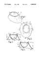
FIG. 2 is a plan view of the device;
FIG. 3 is a sectional view of the device taken along lines 3--3 of FIG. 2;
FIG. 4 is a sectional view, rotated 90 from FIG. 3, and taken along lines 4--4 of FIG. 3;
FIG. 5 is a partial, sagittal section of female sexual anatomy showing, in schematic representation, the posterior aspect of the vaginal tract and the barrier-type device in place covering the cervix, and sealing to the posterior of the vaginal canal;
FIG. 6 illustrates a schematic of the posterior of the vaginal canal from a frontal aspect showing the barrier-type device in place;
FIGS. 7-10 illustrate the structure and operation of the applicator for insertion of the barrier-type device of FIGS. 1-6 into the vagina; and
FIGS. 11 and 12 illustrate an extractor for removal of the barrier-type device from intravaginal placement.
FIG. 13 is an enlarged sectional view of a portion of the barrier-type device shown in FIG. 4.
DETAILED DESCRIPTION OF THE PREFERRED EMBODIMENT
An intravaginal, barrier-type device for preventing conception and infection by sexually-transmitted diseases is illustrated structurally in FIGS. 1-4. Preferably, the device is a single piece formed by molding a flexible, physiologically non-reactive material, such as latex rubber. The device 8 includes a cervical dome 10. The dome preferably has a hemi-spherical or hemi-ovoid shape which forms a cervical enclosure. At the opening of the enclosure, the dome 10 transitions to a fornical rim 12, which in turn, transitions by a backward fold to a vaginal brim 14. As best seen in FIGS. 3 and 4, the dome has a peak, or top, 16.
As FIGS. 1-4 reveal, the vaginal brim circumscribes, or surrounds, the dome and extends downwardly from the rim 12. The brim exhibits lateral symmetry, as illustrated in FIG. 3, where the lateral extensions 14a and 14b of the brim 14 are substantially equal in form and dimension. The width of the brim increases continuously from the anterior to the posterior of the device 8. This increase is revealed in FIGS. 1 and 4. In FIG. 4, the anterior extension 14c of the brim 14 has a smaller dimension 22 than the dimension 23 at the posterior extension 14d of the brim 14. The brim also has an outward bias, or curve, to it, as is seen in FIGS. 1, 3, and 4.
The width of the brim increases with circumferential symmetry from an anterior vaginal location 18 on the anterior extension 14c of the brim to a posterior vaginal location 20 on the posterior portion 14d of the brim. The circumferential symmetry of the brim 14 is illustrated in FIG. 2. In FIG. 2, point A over the lateral extension 14a is displaced in a counterclockwise direction on the rim 12 from the anterior vaginal location by a rim segment equal to the rim segment by which the point B over the lateral extension 14b is displaced on the rim 12 clockwise from the anterior vaginal location 18. As shown in FIG. 3, the dimension 26 reflecting the width of the brim at extension 14a is equal to the dimension 28 reflecting the width of the brim at extension 14b.
An annular lip 24 is formed in the device 8 by an inward extension of the rim 12 along the periphery of the opening into the dome 10. The lip 24 juts into the opening toward the center line 25 of the dome 10. The backward fold of the rim 12 at the lip 24 by which the rim 12 transitions to the brim 14 forms an annular groove 27 between the brim 14 and dome 10.
As shown in the enlargement of FIG. 13, the upper periphery of both dome 10 and brim 14 define a passageway 75 between annular groove 27 and the scoop 76 formed by brim 14. As shown in the relaxed position, the radial width of passageway 75 is not greater than the greatest cross-sectional width of groove 27.
The significance of the structure of the barrier-type device 8 is illustrated in FIGS. 5 and 6. In FIGS. 5 and 6, female anatomy is conventionally illustrated as including a cervix 30 through which the cervical os 32 opens to the interior of the uterus 34. The vagina 36 includes an inner surface 37 which transitions to the cervix 30 by way of a fornix, an anatomical fold or recess. As is known, the fornix increases in depth from its anterior to its posterior aspects, which are usually referred to as the anterior fornix 38 and the posterior fornix 39, respectively. Further, at its rear, the vagina 36 transitions, by way of the anterior vaginal wall 40 to the anterior fornix 38, and by way of the posterior vaginal wall 42 to the posterior fornix 39. As shown in the frontal cross section of FIG. 6, the fornix is laterally symmetrical.
FIGS. 5 and 6 illustrate how the barrier-type device of FIGS. 1-4 is adapted to the anatomy and physiology of the vagina in the vicinity of the cervix. As shown in FIGS. 4 and 5, the proper orientation of the device 8 finds the cervical dome 10 engaging the cervix, which extends through the opening defined by the rim 12. The rim is seated at the bottom of the fornices. The annular lip 24 grips the bottom of the cervix at the fornices, thereby forming a circumferential seal. The brim 14 extends from the bottom of the fornices in close sealing engagement with the walls of the vagina, thereby continuing the circumferential seal along the vagina forwardly from the fornices. The barrier-type device is oriented with respect to the cervix to place the anterior extension 14c against the anterior vaginal wall 40, in the vicinity of the anterior fornix. Similarly, the posterior extension 14d is oriented to engage the posterior vaginal wall 42 in the vicinity of the posterior fornix. As shown in FIG. 6, the orientation of FIG. 5 disposes the lateral rim extensions 14a and 14b against the lateral vaginal walls in the vicinity of the lateral fornices.
As shown in FIGS. 5 and 6, not only does the device seal to the vagina and cervix, it orients the annular groove 27 toward the opening of the vagina. Thus oriented, the groove 27 will trap fluids traveling along the inside of the brim 14 toward the dome 10.
In use, a spermicide such as NONOXYNOL-9, is applied to the total surface of the device 8, and the device is inserted into the vagina to engage the cervix with the orientation illustrated in FIGS. 5 and 6. Thus, seated, the barrier-type device of the invention will seal from the base of the cervix, in the fornices and continuously and circumferentially along the vagina. This seal is superior to the prior art barrier devices. As is known, the diaphragm would engage only the posterior fornix, extending across the top of the vaginal wall forward of the anterior of the cervix. The cervical cap engages only the top of the cervix, and, generally, does not extend fully into the posterior, anterior, and lateral fornices. However, the device 8 fits precisely to the anatomy and physiology of the vagina in the vicinity of the cervix. Such an anatomically adapted form will not only seal effectively when the device is seated, but will also seal reliably by resisting unintentional displacement or dislodgment. The device is retained in place by suction exerted in the cervix by the dome 10, by the grip exerted on the base of the cervix by the annular lip 24, by a snug fitting between the rim 12 of the fornices, and by the outward curve of the brim, which flattens against the vagina. All of these mechanisms help prevent dislodgment of the device and contribute to the seal which the device makes.
An applicator for intravaginal placement of the barrier-type device 8 is illustrated in FIGS. 7-10. The applicator 50 consists of a speculum-type portion with a main body, or a handle, 52 which transitions into a projection 54 having an angle of, preferably, 40° with the main body 52. As seen in FIG. 7, the angled projection 54 has a concave recess 55. A rounded forward edge 56 is provided on the distal end of the projection 54. A movable inserter 57 is slidably disposed in the main portion 52 and moved in the main portion between a first position, indicated by the solid lines in FIG. 7, and a second, release, position denoted in FIG. 7 by the interrupted lines. The inserter 57 consists of two equivalent elongate pieces 57a and 57b having serrated forward faces 60a and 60b and rear flanges 61a and 61b, respectively. The applicator 50 is formed from a physiologically inert material, such as a relatively rigid plastic, and has all of its edges and ends smoothed and rounded to reduce the prospect of injuring the vagina during placement of the device 8.
FIGS. 8-10 illustrate how the applicator is used to place the barrier-type device 8. As shown in FIG. 8, the barrier-type device is carried on the applicator by engagement of the forward end 56 in the groove 27 of the device 8 formed between the dome 10, the rim 12, and the posterior vaginal extension 14d. The brim 14 is grasped between the serrated surfaces 60a and 60b at the anterior vaginal extension 14c. The inserter 57 is retracted to the first position. In this position, the serrated faces 60a and 60b are forced together with the anterior vaginal extension 14c grasped between them. As the inserter 57 is drawn backward to the first position, the barrier-type device is stretched and retained on the applicator 50 by the tension of the flexible material from which the device 8 is formed. Thus arranged, the barrier-type device on the applicator 50 is placed intravaginally, with the device oriented as in FIG. 5.
After traversing the vaginal canal, the end 56 of the applicator 50 will place the posterior vaginal extension 14d of the brim against the posterior vaginal wall and seat the rim 12 in the posterior fornix 39. When this occurs, the anterior vaginal extension 14c will still be forward of the anterior fornix 38. Next, the inserter 57 is slid forwardly in the main body 52 to the second position, which will move the anterior vaginal extension 14c into engagement with the anterior fornix 38. When this occurs, the barrier-type device 8 will be retained in the engagement of FIG. 5 by the mechanisms described above.
Removal of the applicator can be understood with reference to FIGS. 9 and 10. When the barrier-type device is seated by forward movement of the inserter 57, the flexibility of the members 57a and 57b will cause the serrated faces 60a and 60b to spring apart slightly. Next, with the barrier-type device retained in position by suction, the upper member 57b is moved rearwardly toward the first position, which disengages the inserter from the anterior vaginal extension 14c of the brim. The lower member 57a is then pulled rearwardly. This completely disengages the applicator 52 from the anterior fornical extension 14c of the brim, and permits the applicator 52 to be removed.
As shown in FIGS. 11 and 12, an extractor 64 has an elongate portion 66 with a cross section substantially flattened in a plane. The distal tip of the elongate portion 66 transitions to a hook 68. The hook curves backwardly over the elongate portion and is flattened in the same plane. An operating handle 69 is attached to the proximal end of the portion 66, to be substantially perpendicular to the plane of flattening of the portion and hooks.
The barrier-type device 8 is extracted by insertion of the elongate portion 66, hook first, flat into the vagina in the direction of the anterior fornix. When the anterior fornix is encountered, the extractor is rotated 90, by the handle, to bring the hook 68 into engagement with the back of the brim 12 at the anterior vaginal location. The extractor is pulled out, bringing the device 8 with it.
Obviously, many modifications and variations of the present invention are possible in light of the above teachings, and it is therefore understood that within the scope of the disclosed inventive concept, the invention may be practiced other than as specifically described.

Claims (11)

I claim:
1. A barrier-type device for preventing conception and infection by sexually-transmitted diseases, comprising:
a cervical dome fabricated from a flexible material, said dome having an upwardly facing opening and a curved surface extending from said opening to a downwardly facing dome peak; and
a continuous, generally annular fornical rim defining said opening, said rim being folded from said dome inwardly, upwardly, and outwardly, transitioning therefrom into a continuous, annular vaginal brim which circumscribes said cervical dome and extends both outwardly and downwardly, said fornical rim thereby forming an inwardly extending lip and a fluid trapping, inwardly extending groove between said brim and said lip.
2. The barrier-type device of claim 1 wherein the vertical dimension between said rim and the outside edge of said brim increases with circumferential symmetry from an anterior vaginal location on said brim to a posterior vaginal location on said brim which is opposite said anterior vaginal location.
3. The barrier-type device of claim 1 wherein the radial distance between said dome and said brim decreases upwardly to a minimum distance just below said rim, then increases as said brim and said dome transition into said rim.
4. A method of preventing conception and infection by sexually transmitted diseases, comprising the steps of:
providing a barrier-type device having a cervical dome with a fornical rim defining an upwardly facing opening in said dome, said rim folded from said opening both outwardly and downwardly, transitioning therefrom into a continuous, annular vaginal brim which circumscribes said dome, said brim having a vertical dimension between said rim and the outside edge of said brim which increases with circumferential symmetry from an anterior vaginal brim extension to a posterior vaginal brim extension which is diametrically opposite said anterior vaginal brim extension;
placing the device in an intravaginal engagement which situates said dome in a cervical engagement with said fornical rim fornically engaged and said vaginal brim in a continuous, sealing vaginal engagement; and,
wherein said placing step includes orienting said device to place said anterior vaginal brim extension in an anterior vaginal engagement and said posterior vaginal brim extension in a posterior vaginal engagement.
5. The method of preventing conception and infection by sexually transmitted disease of claim 4 wherein said providing step includes said fornical rim being folded from said opening inwardly, upwardly, and outwardly, forming thereby a generally annular, inwardly extending lip and a fluid trapping, inwardly extending groove between said brim and said lip.
6. A method of preventing conception and infection by sexually transmitted diseases, comprising the steps of:
providing a barrier-type device having a cervical dome with a fornical rim defining an upwardly facing opening in said dome, said rim being folded from said opening inwardly, upwardly, and outwardly, transitioning therefrom into a continuous, annular vaginal brim which circumscribes said dome, said inwardly and outwardly folded rim defining a generally annular, inwardly extending, fluid trapping groove at the inner side of said brim proximate said rim;
placing the device in an intravaginal engagement which situates said dome in a cervical engagement with said fornical rim fornically engaged and said vaginal brim in a continuous, sealing vaginal engagement.
7. The method of preventing conception and infection by sexually-transmitted disease of claim 6 including the step of applying spermicide to said vaginal brim, to said dome and to said rim within said groove.
8. A barrier-type device for preventing conception and infection of sexually-transmitted diseases, comprising:
dome means for surrounding a cervix;
continuous brim means connected to and circumscribing said dome means and extending both outwardly and downwardly from said dome means, said brim means being for forming a continuous seal against the vaginal wall proximal to the cervix, and wherein said brim means forms a scoop for fluids;
fluid trapping means defined by an annular, folded fornical rim, said rim connecting said dome means with said brim means, said fluid trapping means being a generally toroidal-shaped cavity in communication with said scoop and being for trapping fluids entering said scoop; and,
wherein said dome means and said brim means mutually define a generally annular passageway between said scoop and said toroidal-shaped cavity, said passageway having a radial width not greater than the greatest cross-sectional width of said cavity.
9. The barrier-type device of claim 8 wherein said fluid trapping means extends radially inwardly of said scoop.
10. The barrier-type device of claim 8 wherein the radial width of said passageway is less than the greatest cross-sectional width of said cavity.
11. The barrier-type device of claim 10 wherein said cavity extends radially inwardly of said passageway.
US07/386,882 1988-02-24 1989-07-31 Device and method for intravaginal, barrier-type prevention of conception and infection Expired - Fee Related US4989618A (en)

Priority Applications (2)

Application Number Priority Date Filing Date Title
US07/386,882 US4989618A (en) 1988-02-24 1989-07-31 Device and method for intravaginal, barrier-type prevention of conception and infection
US07/716,644 US5207232A (en) 1988-02-24 1991-06-17 Device and method for intravaginal, barrier-type prevention of conception and infection

Applications Claiming Priority (2)

Application Number Priority Date Filing Date Title
US07/159,846 US4858624A (en) 1988-02-24 1988-02-24 Device and method for intravaginal, barrier-type prevention of conception and infection
US07/386,882 US4989618A (en) 1988-02-24 1989-07-31 Device and method for intravaginal, barrier-type prevention of conception and infection

Related Parent Applications (1)

Application Number Title Priority Date Filing Date
US07/159,846 Continuation US4858624A (en) 1988-02-24 1988-02-24 Device and method for intravaginal, barrier-type prevention of conception and infection

Related Child Applications (1)

Application Number Title Priority Date Filing Date
US59368790A Continuation 1988-02-24 1990-10-05

Publications (1)

Publication Number Publication Date
US4989618A true US4989618A (en) 1991-02-05

Family

ID=26856364

Family Applications (1)

Application Number Title Priority Date Filing Date
US07/386,882 Expired - Fee Related US4989618A (en) 1988-02-24 1989-07-31 Device and method for intravaginal, barrier-type prevention of conception and infection

Country Status (1)

Country Link
US (1) US4989618A (en)

Cited By (19)

* Cited by examiner, † Cited by third party
Publication number Priority date Publication date Assignee Title
US5771900A (en) * 1997-07-22 1998-06-30 Path Contraceptive diaphragm
US5778886A (en) * 1996-02-27 1998-07-14 Shihata; Alfred Vaginal compositions combining a spermicidal agent and a peroxygen compound
US6737084B2 (en) 2000-06-27 2004-05-18 Qualilife Compositions and methods for enhancing or treating female sexual response
US6796973B1 (en) 1989-12-07 2004-09-28 Instead, Inc. Vaginal discharge collection device and intravaginal drug delivery system
US20050025847A1 (en) * 2003-02-26 2005-02-03 Program For Appropriate Technology In Health Microbicidal compositions and method of use
US20050037033A1 (en) * 2003-05-23 2005-02-17 Program For Appropriate Technology In Health Microbicidal compositions and methods and use
US20080121238A1 (en) * 2006-11-29 2008-05-29 Shihata Alfred A Kit for Contraception and Prevention of Sexually Transmitted Infections
US20080125692A1 (en) * 2006-11-06 2008-05-29 Feemster-Alsberg Research Development Llc Therapeutic Intra-vaginal Devices & Methods
US20110259344A1 (en) * 2010-04-21 2011-10-27 Ahluwalia Prabhat K Fornix manipulator
USD749215S1 (en) 2014-03-11 2016-02-09 Prabhat Kumar Ahluwalia Medical device
USD750779S1 (en) 2014-03-11 2016-03-01 Prabhat Kumar Ahluwalia Medical device
USD751198S1 (en) 2014-03-11 2016-03-08 Prabhat Kumar Ahluwalia Medical device
US9327097B2 (en) 2013-03-12 2016-05-03 Minimally Invasive Surgical Technologies, Inc Uterine manipulator
USD755968S1 (en) 2014-03-11 2016-05-10 Prabhat Kumar Ahluwalia Medical device
USD755966S1 (en) 2014-03-11 2016-05-10 Prabhat Kumar Ahluwalia Medical device
USD755967S1 (en) 2014-03-11 2016-05-10 Prabhat Kumar Ahluwalia Medical device
USD763445S1 (en) 2014-03-11 2016-08-09 Prabhat Kumar Ahluwalia Medical device
USD763446S1 (en) 2014-03-11 2016-08-09 Prabhat Kumar Ahluwalia Medical device
US11389338B2 (en) 2014-09-19 2022-07-19 Outasite, Llc Cervical pad

Citations (18)

* Cited by examiner, † Cited by third party
Publication number Priority date Publication date Assignee Title
US1634555A (en) * 1925-02-16 1927-07-05 William S Peloubet Catamenial sack and womb support
US1949863A (en) * 1932-11-25 1934-03-06 Durex Products Inc Pessary
US2071248A (en) * 1935-11-27 1937-02-16 Frank L Campbell Pessary
US2104275A (en) * 1937-05-11 1938-01-04 Schleicher Lawrence Pessary applicator
US2110962A (en) * 1936-01-30 1938-03-15 Ruth W Munro Medical device
US2157689A (en) * 1935-11-02 1939-05-09 Jr Percy L Clark Pessary
US2218009A (en) * 1931-08-10 1940-10-15 Jr William L Schmitz Introducer
US2324656A (en) * 1940-09-03 1943-07-20 Cranston G Vincent Pessary
US2443943A (en) * 1945-08-28 1948-06-22 Durex Products Inc Pessary
US2625154A (en) * 1948-06-10 1953-01-13 Durex Products Inc Laterally collapsible pessary
US2638896A (en) * 1948-07-10 1953-05-19 John T Clark Spring structure
US2664082A (en) * 1948-03-15 1953-12-29 Walter J Heuboski Pessary
US2676589A (en) * 1949-12-08 1954-04-27 Walter J Heuboski Folded pessary
US2823669A (en) * 1956-07-20 1958-02-18 Holland Rantos Company Inc Vaginal diaphragm
US3128762A (en) * 1961-08-23 1964-04-14 John C Young Mechanical contraceptives
US3130721A (en) * 1961-06-26 1964-04-28 John C Young Mechanical contraceptives
US4031886A (en) * 1975-09-11 1977-06-28 Morhenn Vera B Occlusive pessary
US4286593A (en) * 1980-05-05 1981-09-01 Place Virgil A Vaginal contraceptive shield

Patent Citations (18)

* Cited by examiner, † Cited by third party
Publication number Priority date Publication date Assignee Title
US1634555A (en) * 1925-02-16 1927-07-05 William S Peloubet Catamenial sack and womb support
US2218009A (en) * 1931-08-10 1940-10-15 Jr William L Schmitz Introducer
US1949863A (en) * 1932-11-25 1934-03-06 Durex Products Inc Pessary
US2157689A (en) * 1935-11-02 1939-05-09 Jr Percy L Clark Pessary
US2071248A (en) * 1935-11-27 1937-02-16 Frank L Campbell Pessary
US2110962A (en) * 1936-01-30 1938-03-15 Ruth W Munro Medical device
US2104275A (en) * 1937-05-11 1938-01-04 Schleicher Lawrence Pessary applicator
US2324656A (en) * 1940-09-03 1943-07-20 Cranston G Vincent Pessary
US2443943A (en) * 1945-08-28 1948-06-22 Durex Products Inc Pessary
US2664082A (en) * 1948-03-15 1953-12-29 Walter J Heuboski Pessary
US2625154A (en) * 1948-06-10 1953-01-13 Durex Products Inc Laterally collapsible pessary
US2638896A (en) * 1948-07-10 1953-05-19 John T Clark Spring structure
US2676589A (en) * 1949-12-08 1954-04-27 Walter J Heuboski Folded pessary
US2823669A (en) * 1956-07-20 1958-02-18 Holland Rantos Company Inc Vaginal diaphragm
US3130721A (en) * 1961-06-26 1964-04-28 John C Young Mechanical contraceptives
US3128762A (en) * 1961-08-23 1964-04-14 John C Young Mechanical contraceptives
US4031886A (en) * 1975-09-11 1977-06-28 Morhenn Vera B Occlusive pessary
US4286593A (en) * 1980-05-05 1981-09-01 Place Virgil A Vaginal contraceptive shield

Non-Patent Citations (6)

* Cited by examiner, † Cited by third party
Title
"Contraception Update", from Consultant, vol. 27, No. 11, Nov. 1987, pp. 23-32.
"Conventional Methods of Contraception: Condom, Diaphragm, and Vaginal Foam", from Clinical Obstetrics and Gynecology, vol. 17, No. 1, Mar. 1974, pp. 21-33.
"The Diaphragm and Other Intravaginal Barriers", from Population Reports, Series H, No. 4, Jan. 1976, pp. H-57 through H-74.
Contraception Update , from Consultant, vol. 27, No. 11, Nov. 1987, pp. 23 32. *
Conventional Methods of Contraception: Condom, Diaphragm, and Vaginal Foam , from Clinical Obstetrics and Gynecology, vol. 17, No. 1, Mar. 1974, pp. 21 33. *
The Diaphragm and Other Intravaginal Barriers , from Population Reports, Series H, No. 4, Jan. 1976, pp. H 57 through H 74. *

Cited By (27)

* Cited by examiner, † Cited by third party
Publication number Priority date Publication date Assignee Title
US6796973B1 (en) 1989-12-07 2004-09-28 Instead, Inc. Vaginal discharge collection device and intravaginal drug delivery system
US5778886A (en) * 1996-02-27 1998-07-14 Shihata; Alfred Vaginal compositions combining a spermicidal agent and a peroxygen compound
US5771900A (en) * 1997-07-22 1998-06-30 Path Contraceptive diaphragm
US6737084B2 (en) 2000-06-27 2004-05-18 Qualilife Compositions and methods for enhancing or treating female sexual response
US7875299B2 (en) 2000-06-27 2011-01-25 Semprae Laboratories, Inc. Compositions and methods for enhancing or treating female sexual response
US8128972B2 (en) 2000-06-27 2012-03-06 Semprae Laboratories, Inc. Compositions and methods for enhancing and treating female sexual response
US20050025847A1 (en) * 2003-02-26 2005-02-03 Program For Appropriate Technology In Health Microbicidal compositions and method of use
US20050037033A1 (en) * 2003-05-23 2005-02-17 Program For Appropriate Technology In Health Microbicidal compositions and methods and use
US20080125692A1 (en) * 2006-11-06 2008-05-29 Feemster-Alsberg Research Development Llc Therapeutic Intra-vaginal Devices & Methods
US10398591B2 (en) 2006-11-06 2019-09-03 Stacy L. Feemster Therapeutic intra-vaginal devices and methods
US8728140B2 (en) 2006-11-06 2014-05-20 Stacy Lee Feemster Therapeutic intra-vaginal devices and methods
US20080121238A1 (en) * 2006-11-29 2008-05-29 Shihata Alfred A Kit for Contraception and Prevention of Sexually Transmitted Infections
US8770200B2 (en) * 2010-04-21 2014-07-08 Minimally Invasive Surgical Technologies, Inc. Fornix manipulator
US9592078B2 (en) 2010-04-21 2017-03-14 Minimally Invasive Surgical Technologies, Inc. Fornix manipulator
US20110259344A1 (en) * 2010-04-21 2011-10-27 Ahluwalia Prabhat K Fornix manipulator
US9522252B2 (en) 2013-03-12 2016-12-20 Prabhat K. Ahluwalia Uterine manipulator
US9327097B2 (en) 2013-03-12 2016-05-03 Minimally Invasive Surgical Technologies, Inc Uterine manipulator
USD755968S1 (en) 2014-03-11 2016-05-10 Prabhat Kumar Ahluwalia Medical device
USD755966S1 (en) 2014-03-11 2016-05-10 Prabhat Kumar Ahluwalia Medical device
USD755967S1 (en) 2014-03-11 2016-05-10 Prabhat Kumar Ahluwalia Medical device
USD763445S1 (en) 2014-03-11 2016-08-09 Prabhat Kumar Ahluwalia Medical device
USD763446S1 (en) 2014-03-11 2016-08-09 Prabhat Kumar Ahluwalia Medical device
USD749215S1 (en) 2014-03-11 2016-02-09 Prabhat Kumar Ahluwalia Medical device
USD751198S1 (en) 2014-03-11 2016-03-08 Prabhat Kumar Ahluwalia Medical device
USD750779S1 (en) 2014-03-11 2016-03-01 Prabhat Kumar Ahluwalia Medical device
US11389338B2 (en) 2014-09-19 2022-07-19 Outasite, Llc Cervical pad
US11911243B2 (en) 2014-09-19 2024-02-27 Outasite, Llc Cervical pad

Similar Documents

Publication Publication Date Title
US4858624A (en) Device and method for intravaginal, barrier-type prevention of conception and infection
US4989618A (en) Device and method for intravaginal, barrier-type prevention of conception and infection
US5207232A (en) Device and method for intravaginal, barrier-type prevention of conception and infection
US3683904A (en) Pessaries
US4381771A (en) Female contraceptive
US20140109915A1 (en) Female condom
US5515862A (en) Female condom
US20060278236A1 (en) Universal unisex safety condom
US4428370A (en) Insertion unit for a vaginal diaphragm
US4703752A (en) Contraceptive device
US10335312B2 (en) Vaginal ring removal device and methods
US4183358A (en) Male contraceptive device
US5598852A (en) Receptive condom assembly
US20080257361A1 (en) Male condom with tension band
US20110303226A1 (en) Condom
US5701914A (en) Male contraceptive
US3842827A (en) Endocervical contraceptive device
US20090320855A1 (en) Kit for Contraception and Prevention of Sexually Transmitted Infections
US5353811A (en) Trap
US20120152258A1 (en) Condom
ZA200501858B (en) Female condom
CN215688930U (en) Time-delay type condom
US20150057495A1 (en) Safe Uni-Sex-Organ Insertion Membrane Sponge Assembly
WO2001037766A1 (en) A contraceptive bag for females
JPS63234968A (en) Contraceptive sanitrary sac for woman

Legal Events

Date Code Title Description
AS Assignment

Owner name: SHIHATA, ALFRED A. M.D., CALIFORNIA

Free format text: ASSIGNMENT OF ASSIGNORS INTEREST.;ASSIGNOR:VANCE PRODUCTS INCORPORATED D/B/A COOK UROLOGICAL INCORPORATED AND COOK OB/GYN;REEL/FRAME:005755/0038

Effective date: 19910306

FEPP Fee payment procedure

Free format text: PAT HOLDER CLAIMS SMALL ENTITY STATUS - SMALL BUSINESS (ORIGINAL EVENT CODE: SM02); ENTITY STATUS OF PATENT OWNER: SMALL ENTITY

Free format text: PAYOR NUMBER ASSIGNED (ORIGINAL EVENT CODE: ASPN); ENTITY STATUS OF PATENT OWNER: SMALL ENTITY

FPAY Fee payment

Year of fee payment: 4

AS Assignment

Owner name: FEMCAP, INC., CALIFORNIA

Free format text: ASSIGNMENT OF ASSIGNORS INTEREST;ASSIGNOR:SHIHATA, ALFRED A., M.D.;REEL/FRAME:007553/0837

Effective date: 19950708

FPAY Fee payment

Year of fee payment: 8

REMI Maintenance fee reminder mailed
LAPS Lapse for failure to pay maintenance fees
FP Lapsed due to failure to pay maintenance fee

Effective date: 20030205

STCH Information on status: patent discontinuation

Free format text: PATENT EXPIRED DUE TO NONPAYMENT OF MAINTENANCE FEES UNDER 37 CFR 1.362