US4978017A - Tamper-indicating plastic closure - Google Patents
Tamper-indicating plastic closure Download PDFInfo
- Publication number
- US4978017A US4978017A US07/465,301 US46530190A US4978017A US 4978017 A US4978017 A US 4978017A US 46530190 A US46530190 A US 46530190A US 4978017 A US4978017 A US 4978017A
- Authority
- US
- United States
- Prior art keywords
- closure
- pilfer band
- tamper
- skirt portion
- frangible
- Prior art date
- Legal status (The legal status is an assumption and is not a legal conclusion. Google has not performed a legal analysis and makes no representation as to the accuracy of the status listed.)
- Expired - Fee Related
Links
- 239000011324 bead Substances 0.000 claims abstract description 41
- 230000015572 biosynthetic process Effects 0.000 claims description 10
- 230000002708 enhancing effect Effects 0.000 claims description 2
- 230000002452 interceptive effect Effects 0.000 abstract description 17
- 230000003993 interaction Effects 0.000 description 8
- 230000006870 function Effects 0.000 description 4
- 230000009471 action Effects 0.000 description 3
- 238000012986 modification Methods 0.000 description 3
- 230000004048 modification Effects 0.000 description 3
- 238000000465 moulding Methods 0.000 description 3
- 238000007789 sealing Methods 0.000 description 3
- 238000000748 compression moulding Methods 0.000 description 2
- 238000005520 cutting process Methods 0.000 description 2
- 230000009977 dual effect Effects 0.000 description 2
- 238000005304 joining Methods 0.000 description 2
- 238000004519 manufacturing process Methods 0.000 description 2
- 238000000034 method Methods 0.000 description 2
- 238000000926 separation method Methods 0.000 description 2
- 238000013022 venting Methods 0.000 description 2
- 230000004075 alteration Effects 0.000 description 1
- 239000002131 composite material Substances 0.000 description 1
- 150000001875 compounds Chemical class 0.000 description 1
- 238000010276 construction Methods 0.000 description 1
- 238000001746 injection moulding Methods 0.000 description 1
- 230000013011 mating Effects 0.000 description 1
- 238000004806 packaging method and process Methods 0.000 description 1
- 238000009877 rendering Methods 0.000 description 1
- 230000000007 visual effect Effects 0.000 description 1
Images


Classifications
-
- B—PERFORMING OPERATIONS; TRANSPORTING
- B65—CONVEYING; PACKING; STORING; HANDLING THIN OR FILAMENTARY MATERIAL
- B65D—CONTAINERS FOR STORAGE OR TRANSPORT OF ARTICLES OR MATERIALS, e.g. BAGS, BARRELS, BOTTLES, BOXES, CANS, CARTONS, CRATES, DRUMS, JARS, TANKS, HOPPERS, FORWARDING CONTAINERS; ACCESSORIES, CLOSURES, OR FITTINGS THEREFOR; PACKAGING ELEMENTS; PACKAGES
- B65D41/00—Caps, e.g. crown caps or crown seals, i.e. members having parts arranged for engagement with the external periphery of a neck or wall defining a pouring opening or discharge aperture; Protective cap-like covers for closure members, e.g. decorative covers of metal foil or paper
- B65D41/32—Caps or cap-like covers with lines of weakness, tearing-strips, tags, or like opening or removal devices, e.g. to facilitate formation of pouring openings
- B65D41/34—Threaded or like caps or cap-like covers provided with tamper elements formed in, or attached to, the closure skirt
- B65D41/3423—Threaded or like caps or cap-like covers provided with tamper elements formed in, or attached to, the closure skirt with flexible tabs, or elements rotated from a non-engaging to an engaging position, formed on the tamper element or in the closure skirt
- B65D41/3428—Threaded or like caps or cap-like covers provided with tamper elements formed in, or attached to, the closure skirt with flexible tabs, or elements rotated from a non-engaging to an engaging position, formed on the tamper element or in the closure skirt the tamper element being integrally connected to the closure by means of bridges
-
- B—PERFORMING OPERATIONS; TRANSPORTING
- B65—CONVEYING; PACKING; STORING; HANDLING THIN OR FILAMENTARY MATERIAL
- B65D—CONTAINERS FOR STORAGE OR TRANSPORT OF ARTICLES OR MATERIALS, e.g. BAGS, BARRELS, BOTTLES, BOXES, CANS, CARTONS, CRATES, DRUMS, JARS, TANKS, HOPPERS, FORWARDING CONTAINERS; ACCESSORIES, CLOSURES, OR FITTINGS THEREFOR; PACKAGING ELEMENTS; PACKAGES
- B65D41/00—Caps, e.g. crown caps or crown seals, i.e. members having parts arranged for engagement with the external periphery of a neck or wall defining a pouring opening or discharge aperture; Protective cap-like covers for closure members, e.g. decorative covers of metal foil or paper
- B65D41/32—Caps or cap-like covers with lines of weakness, tearing-strips, tags, or like opening or removal devices, e.g. to facilitate formation of pouring openings
- B65D41/34—Threaded or like caps or cap-like covers provided with tamper elements formed in, or attached to, the closure skirt
- B65D41/3442—Threaded or like caps or cap-like covers provided with tamper elements formed in, or attached to, the closure skirt with rigid bead or projections formed on the tamper element and coacting with bead or projections on the container
- B65D41/3447—Threaded or like caps or cap-like covers provided with tamper elements formed in, or attached to, the closure skirt with rigid bead or projections formed on the tamper element and coacting with bead or projections on the container the tamper element being integrally connected to the closure by means of bridges
Definitions
- the present invention relates generally to tamper-indicating or tamper evident packaging arrangements, and more particularly to a tamper-indicating plastic closure for a container which functions to provide two modes of interference with the container for enhanced tamper resistance.
- closures of this nature include an upper cap portion, and a depending pilfer band arranged to interact and cooperate with the container to which the closure is applied.
- the philfer band is typically configured so as to fracture and/or separate from the closure cap attendant to closure removal, thereby providing clearly discernable evidence that the container has been partially or completely opened.
- a tamper-indicating closure it is desirable for a tamper-indicating closure to be as resistant as possible to tampering or the like without visibly discernable evidence thereof.
- the present plastic closure has been particularly configured for economical and efficient manufacture for use on existing containers, with the closure being highly resistant to tampering, consistent and reliable in performance, and highly versatile for use with a wide variety of different containers.
- the present invention relates to a tamper-indicating plastic closure for a container having a typical annular locking ring positioned adjacent to and beneath the threads on the neck portion of the container.
- the closure includes a pilfer band having a plurality of inwardly extending flexible tabs, with the pilfer band further including a coacting interference bead positioned beneath the flexible tabs.
- the pilfer band functions to provide dual modes of interfering interaction with the container locking ring for tamper-indication.
- the present plastic closure includes a plastic cap having a circular top wall portion, and an annular depending cylindrical skirt portion.
- the skirt portion includes an internal thread formation adapted for coaction with a mating thread formation on the neck portion of the associated container for retaining the closure thereon after application to the container.
- the present closure further includes an annular, integrally formed pilfer band depending from the skirt portion of the closure cap.
- the pilfer band is at least partially detachably connected to the skirt portion of the cap by a plurality of circumferentially spaced frangible ribs.
- the frangible ribs extend between inside surfaces of the skirt portion and pilfer band, with the skirt portion and pilfer band otherwise being distinguished and separated from each other by a circumferential score line which extends partially into the frangible ribs.
- the pilfer band includes an annular band portion, and a plurality of circumferentially spaced, inwardly extending flexible tabs which extend inwardly of the annular band portion.
- the pilfer band further includes an annular interference bead extending generally inwardly of the annular band portion, with the interference bead positioned beneath the inwardly extending flexible tabs.
- the flexible tabs In this disposition of the flexible tabs, they are positioned for interfering engagement with the generally downwardly facing surface of the container locking ring, whereby in this first mode of interference, the free end portions of the flexible tabs engage the locking ring for fracturing the frangible ribs which at least partially detachably connect the pilfer band to the skirt portion of the closure cap. Clearly visible evidence of opening is thus provided.
- the flexible tabs cooperate and coact with the interference bead of the pilfer band to again interferingly engage and coact with the container locking ring.
- the flexible tabs are engageable with the container locking ring in the event that the flexible tabs assume an angularly downwardly and inwardly extending disposition relative to the annular band portion of the pilfer band.
- the flexible tabs are engageable with the container locking ring by disposition between the locking ring and the annular interference bead.
- the flexible tabs and interference bead are dimensioned relative to the container locking ring so as to resist opening movement of the closure, thereby fracturing the frangible ribs joining the pilfer band to the skirt portion. Again, clear visual evidence of opening is achieved.
- a scoring bead can be provided which extends circumferentially on the inside surface of the closure, and which desirably acts to support the interior of the closure during formation of the circumferential score which distinguishes the pilfer band from the skirt portion of the closure.
- at least some of the frangible ribs of the construction can be configured to extend on the inside surface of the pilfer band between adjacent ones of the flexible tabs. Such ribs desirably function to center the pilfer band on the associated container with respect to the locking ring thereof, thus further enhancing tamper resistance.
- a plurality of circumferentially spaced prestressing projections can be provided on the inside of the pilfer band, with these projections being engageable with the container locking ring for prestressing the frangible ribs joining the pilfer band to the closure skirt portion.
- This prestressing arrangement can desirably promote failure of the frangible ribs in the intended manner.
- FIG. 1 is a side elevational view, in partial cross-section, of a tamper-indicating plastic closure embodying the principles of the present invention applied to an associated container;
- FIG. 2 is a cross-sectional view of the novel tamper-indicating closure
- FIG. 3 is a fragmentary, side-elevational view, in partial cross-section illustrating application of the novel closure to the associated container;
- FIG. 4 is a view similar to FIG. 3 illustrating the closure after application to the associated container, and in a position for providing a first mode of interfering engagement with the container;
- FIG. 5 is a view similar to FIG. 4, illustrating the closure in position for effecting a second mode of interfering engagement with the associated container;
- FIGS. 6a and 6b are views similar to FIG. 5, further illustrating the second mode of interfering engagement of the closure with the associated container;
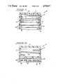
- FIG. 7 is a fragmentary, cross-sectional view of a further embodiment of the present tamper-indicating plastic closure.
- FIG. 8 is a view similar to FIG. 7 illustrating another embodiment of the present tamper-indicating closure.
- Closure 10 can be made by various injection-molding or compression-molding techniques, and it can be formed in accordance with the compression-molding techniques taught in U.S. Pat. No. 4,497,765, which is incorporated herein by reference.
- closure 10 includes an upper generally cup-shaped closure cap 12 including a circular top wall portion 14, and a depending, annular cylindrical skirt portion 16.
- Skirt portion 16 preferably includes an internal thread formation 18 configured for threading engagement in cooperation with the threads T of an associated container C to which the closure is fitted.
- the plastic closure can be provided with an associated sealing liner, such as illustrated in the above-referenced patent.
- the present closure further includes an annular pilfer band 20 depending from and at least partially detachably connected to skirt portion 16 of the closure cap.
- Pilfer band 20 preferably comprises a continuous annular band portion 22 arranged in substantial vertical alignment with skirt portion 16.
- the pilfer band is at least partially detachably connected to the skirt portion by a plurality of circumferentially spaced frangible ribs 24 which extend between the inside surfaces of the skirt portion 16 and the band portion 22 of the pilfer band.
- the pilfer band 20 is otherwise distinguished and separated from the skirt portion 16 by a circumferentially extending score line 26.
- score line 26 and frangible rib 24 together cooperate to provide the desired frangible connection between the pilfer band 20 and the closure cap 12.
- the closure cap 12 and the pilfer band 20 are formed integrally with each other during molding, with the ribs 24 molded on the inside surfaces of the skirt portion and pilfer band.
- score line 26 is formed, preferably by use of a scoring cutting blade, thereby distinguishing and separating the pilfer band 20 from the skirt portion 16, with the score line 26 extending partially into the ribs 24.
- the unscored, "residual" portions of the frangible ribs 24 collectively provide the desired frangible connection between the pilfer band and the skirt portion.
- an integral connector portion can be provided between the pilfer band and the skirt portion (such as by leaving a portion of the closure uncut by score line 26) whereby the pilfer band remains connected to the skirt portion 16 after fracture of the ribs.
- one or more fracturable areas can be provided in the pilfer band itself, whereby the pilfer band splits and fractures during closure removal from the associated container.
- the present closure has been specifically configured to provide a very high degree of tamper resistance, and in particular provides two distinct and separate modes of interfering interaction with the associated container.
- the pilfer band includes a plurality of circumferentially spaced, inwardly extending flexible tabs 28 which extend inwardly from the annular band portion 22 of the pilfer band.
- twelve evenly spaced tabs 28 are provided about the circumference of the pilfer band, with each tab having a width of about 0.240 inches, and a thickness of between about 0.012 inches and 0.020 inches.
- the free end portions of adjacent ones of the tabs 28 are closely spaced (about 0.020 inch spacing) when the tabs extend horizontally inwardly.
- This horizontally inwardly extending orientation of the tabs is indicated in phantom line, and represents the orientation in which the flexible tabs 28 are preferably molded.
- the flexible tabs 28 cooperate with an annular locking ring portion L of container C for effecting fracture of frangible ribs 24, thereby providing the desired tamper-indication.
- the free end portions of the flexible tabs are engageable with the locking ring L.
- the flexible tabs are configured to cooperate with an annular interference bead 30 provided generally at the lower edge of annular band portion 22 of the pilfer band 20.
- the interference bead 30 is positioned beneath the flexible tabs 28, with the upper, inward edge portion of the interference bead positioned relative to the flexible tabs so that this edge portion is engaged by the tabs in the second failure mode.
- the inside diameter of the interference bead is about equal to or slightly less than an inside diameter collectively defined by the inside surfaces of the circumferentially spaced frangible ribs 24.
- the flexible tabs 28 engage the container C and are moved upwardly generally to an upwardly extending, out-of-the-way disposition as the pilfer band moves downwardly relative to the container threads T and the container locking ring L.
- the flexible tabs 28 are preferably provided with a thickness about equal to the radial dimension of the frangible ribs 24, or the tabs 28 are otherwise configured to collectively define an inside diameter about equal to an inside diameter collectively defined by the ribs 24.
- each flexible tab 28 is of a generally planar configuration, having a thickness dimensioned between about 0.012 inches and 0.020 inches.
- each flexible tab 28 is preferably dimensioned and configured for sufficient thickness, in the direction from its free end to its base integral with the band portion 22, so as to exhibit sufficient resistance to collapse or deformation to thereby provide the desired interfering interaction with locking band L.
- each of the tabs 28 may be of a non-planar configuration, such as being slightly curved when viewed in cross-section perpendicular to the length of each tab, or similarly, of a generally angled or compound configuration when similarly viewed. As will be appreciated, such arrangements can act to enhance the "column strength" of each flexible tab for providing the desired interfering engagement with locking ring L.
- the flexible tabs 28 are configured for cooperation with interference bead 30 to provide a second and distinct mode of interfering engagement with the container locking ring L.
- the flexible tabs 28 In the event that the flexible tabs 28 are moved from their angularly upwardly and inwardly disposition (such as by unauthorized manipulation or the like, which is desirably inhibited by the inwardly extending bead 30) the flexible tabs will assume an angularly downwardly and inwardly extending disposition, as illustrated in FIG. 5. In this orientation of the tabs, the tabs are positioned for engagement with the container locking ring L by disposition between the container locking ring and the upper inward edge of the interference bead 30.
- FIGS. 6a and 6b where in FIG. 6a, a flexible tab 28 is illustrated between the locking ring L and the interference bead 30, with FIG. 6b illustrating the subsequent failure of frangible rib 24 and separation along score line 26.
- FIG. 7 therein is illustrated an alternate embodiment of the present tamper-indicating closure.
- this embodiment is the same as the previously described embodiment, although it will be noted that the closure illustrated in FIG. 7 shows the provision of a sealing liner 15 adjacent to top wall portion 14, and a vent groove 17 traversing the internal thread formation 18, with the vent groove 17 extending into the cylindrical skirt portion 16 of the closure.
- the provision of one or more vent grooves 17 facilitates venting of gas pressure, attendant to closure removal, when the present closure is used in connection with a container having carbonated contents or the like.
- the closure 10 includes a pilfer band 20 which is distinguished and at least partially separated from the skirt portion 16 by a circumferential score 26.
- the pilfer band 20 includes a plurality (twelve being presently preferred) of circumferentially spaced, inwardly extending flexible tabs 28, again configured to provide a dual mode of interference with the locking ring of an associated container.
- an inwardly extending interference bead 30 is positioned beneath the flexible tabs 28, with the tabs 28 being engageable with the interference bead 30 in the second mode of interaction of the closure with an associated container.
- the frangible connection between the pilfer band 20 and the skirt portion 16 is provided by a plurality of circumferentially spaced, frangible ribs 124 which extend between the inside surfaces of the skirt portion and the pilfer band.
- frangible ribs 124 extend on the inside surface of the band portion 22 of the pilfer band 20 between adjacent ones of the flexible tabs 28.
- each of the illustrated frangible ribs 124 is so configured.
- This configuration of the frangible ribs 124 desirably acts to center the pilfer band 20 on the associated container C with respect to the container locking ring L.
- This configuration of the frangible ribs 124 a very limited amount of clearance is provided between the container locking ring L and the inwardly facing surfaces of the frangible ribs 124 when the closure 10 is fully seated on the associated container.
- ribs 124 are rendered fracturable by virtue of the score line 26 partially extending into at least some of the ribs.
- this embodiment includes a circumferentially extending scoring bead 127 on the inside of the closure, with the scoring bead 127 preferably extending continuously along the inside of the closure, and with circumferential score line 26 positioned beneath the scoring bead.
- a scoring mandrel inserted into the closure is preferably employed, with a scoring knife or the like then applied to the exterior surface of the closure.
- a scoring knife or the like it is presently preferred that position of the scoring knife be referenced relative to the interiorly-positioned scoring mandrel.
- the scoring bead 127 is configured to securely engage and seat against the scoring mandrel, whereby highly efficient and accurate formation of the score line 26, with the desired degree of partial cutting of the frangible ribs 124, is readily accomplished.
- the flexible tabs 28 are preferably provided with a thickness about equal to the radial dimension of frangible ribs 124. This preferred dimensional relation permits the tabs 28 to desirably support the interior of the closure during scoring (when the tabs 28 are flexed upwardly against the inside surface of the closure) in absence of the scoring bead 127.
- a further feature of the embodiment of FIG. 7 concerns the formation of each of the frangible ribs 124 with an upper portion 125 which extends on the inside surface of skirt portion 16 above scoring bead 127.
- This configuration of the frangible ribs has been found to desirably enhance the columnar strength of the overall closure, which facilitates high-speed ejection from the associated molding apparatus.
- FIG. 8 therein is illustrated a further alternate embodiment of the present closure.
- this embodiment is like that described above and illustrated in FIG. 7, although the embodiment of FIG. 8 does not include a scoring bead 127.
- the absence of the scoring bead, together with the extended configuration of frangible ribs 124 (with upper portions 125) can enhance the gas venting characteristics of the closure.
- this embodiment of the present tamper-indicating closure includes an arrangement for prestressing the frangible connection between the pilfer band 20 and the skirt portion 16 provided by the frangible ribs 124.
- a plurality of circumferentially spaced, prestressing projections 131 are provided on the inside surface of the band portion 20 of the pilfer band.
- these prestressing projections 131 are each positioned on a respective one of the frangible ribs 124.
- the prestressing projections 131 are provided on alternate ones of the frangible ribs 124, but a fewer or greater number of the projections 131 can be similarly provided.
- Projections 131 can be provided to prestress the frangible ribs 124 attendant to both application and removal of the closure. During application of the closure to the associated container, the projections 131 are engageable with the container locking ring L, thus acting to expand and "bell out” the pilfer band 20 attendant to application. This action can act to weaken the unscored, residual portion of each frangible rib 124, thereby facilitating failure of the frangible ribs in the intended manner during closure remoVal.
- the prestressing projections 131 can cooperate with the locking ring L during closure removal. In particular, this can occur in conjunction with stressing and fracture of the ribs 124 when tabs 28 extend angularly downwardly, and are positioned between the container locking ring L and interference bead 30. Attendant to this action, the projections 131 provide additional interference with the container locking ring, thus desirably subjecting the frangible ribs 14 to additional stress to assure fracture and failure of the ribs.
- a further feature of the embodiment of FIG. 8 concerns configuring the pilfer band 20 for fracture of the band portion 22, which is ordinarily desired, as discussed above, in conjunction with the provision of an unscored connector portion which integrally joins the pilfer band to the skirt portion 16 after fracture of ribs 124. By such an arrangement, the pilfer band remains joined to, but partially detached from, the skirt portion 16.
- FIG. 8 illustrates the manner in which a vertical score is preferably formed in the pilfer band 20.
- an external scoring knife is preferably applied to the pilfer band so as to form one or more scores extending to a depth as illustrated in phantom line at 133.
- such vertical scoring is provided between one of the flexible tabs 28 and an adjacent frangible rib 124, so that such vertical scoring does not extend into either the tab 28 or the rib 124.
- the vertical scoring extend partially, but not completely, into the interference bead 30, to thereby define a fracturable residual portion 135 of the pilfer band.
- This arrangement preserves a desired degree of strength in the pilfer band, to facilitate high-speed application, while still rendering the pilfer band fracturable in the intended manner.
- the present closure a high degree of tamper-resistance is provided by the present closure.
- various modifications and departures from the illustrated embodiment can be effected.
- the number, spacing, thickness, and configuration of the flexible tabs 28 can be varied and selected while keeping with the principles disclosed herein.
- the annular interference bead 30 is preferably substantially continuous in nature for providing additional circumferential hoop strength for the closure, segmented or otherwise discontinuous configurations for the interference bead can be alternately employed.
- a closure embodying the present invention may be composite in nature, such as a combination metallic and plastic closure (with or without a separate sealing liner).
Landscapes
- Engineering & Computer Science (AREA)
- Mechanical Engineering (AREA)
- Closures For Containers (AREA)
Abstract
Description
Claims (14)
Priority Applications (12)
| Application Number | Priority Date | Filing Date | Title |
|---|---|---|---|
| US07/465,301 US4978017A (en) | 1989-04-26 | 1990-01-23 | Tamper-indicating plastic closure |
| ES90101729T ES2048330T3 (en) | 1989-01-30 | 1990-01-29 | CLOSING OF PLASTIC VIOLATION INDICATOR. |
| EP90101729A EP0381118B1 (en) | 1989-01-30 | 1990-01-29 | Tamper-indicating plastic closure |
| DE1990604820 DE69004820T2 (en) | 1989-01-30 | 1990-01-29 | Guarantee closure made of plastic. |
| CA 2008769 CA2008769C (en) | 1989-01-30 | 1990-01-29 | Tamper-indicating plastic closure |
| NO900407A NO178997C (en) | 1989-01-30 | 1990-01-29 | Manipulation indicating plastic closures |
| DK23690A DK174625B1 (en) | 1989-01-30 | 1990-01-29 | Warranty closures made of plastic |
| AU48910/90A AU627270B2 (en) | 1989-01-30 | 1990-01-30 | Tamper-indicating plastic closure |
| AR31604990A AR246724A1 (en) | 1989-01-30 | 1990-01-30 | Tamper-indicating plastic closure |
| BR9000381A BR9000381A (en) | 1989-01-30 | 1990-01-30 | PLASTIC CLOSURE VIOLATION INDICATOR |
| JP2020379A JP2810936B2 (en) | 1989-01-30 | 1990-01-30 | Plastic lid device to reveal opening |
| NZ23229790A NZ232297A (en) | 1989-01-30 | 1990-01-30 | Tamper indicating plastics closure; frangible band with internal interference on container neck |
Applications Claiming Priority (2)
| Application Number | Priority Date | Filing Date | Title |
|---|---|---|---|
| US07343995 US4938370B1 (en) | 1989-04-26 | 1989-04-26 | Tamper-indicating plastic closure |
| US07/465,301 US4978017A (en) | 1989-04-26 | 1990-01-23 | Tamper-indicating plastic closure |
Related Parent Applications (1)
| Application Number | Title | Priority Date | Filing Date |
|---|---|---|---|
| US07343995 Continuation-In-Part US4938370B1 (en) | 1989-01-30 | 1989-04-26 | Tamper-indicating plastic closure |
Publications (1)
| Publication Number | Publication Date |
|---|---|
| US4978017A true US4978017A (en) | 1990-12-18 |
Family
ID=26993717
Family Applications (1)
| Application Number | Title | Priority Date | Filing Date |
|---|---|---|---|
| US07/465,301 Expired - Fee Related US4978017A (en) | 1989-01-30 | 1990-01-23 | Tamper-indicating plastic closure |
Country Status (1)
| Country | Link |
|---|---|
| US (1) | US4978017A (en) |
Cited By (40)
| Publication number | Priority date | Publication date | Assignee | Title |
|---|---|---|---|---|
| US5064084A (en) * | 1990-08-27 | 1991-11-12 | H-C Industries, Inc. | Composite closure with seal proportioning lip |
| US5107998A (en) * | 1991-06-14 | 1992-04-28 | Bruno Zumbuhl | Tamper proof ring for threaded closures |
| US5167335A (en) * | 1991-04-09 | 1992-12-01 | H-C Industries, Inc. | Tamper-indicating plastic closure |
| US5205426A (en) * | 1991-04-09 | 1993-04-27 | H-C Industries, Inc. | Tamper-indicating plastic closure |
| US5242068A (en) * | 1992-08-07 | 1993-09-07 | H-C Industries, Inc. | Tamper-indicating plastic closure |
| US5273173A (en) * | 1990-02-05 | 1993-12-28 | Lynes Holding S.A. | Screw top |
| EP0593396A1 (en) * | 1992-10-14 | 1994-04-20 | Crown Cork & Seal Company, Inc. | Tamper proof plastic closure |
| US5320234A (en) * | 1992-10-07 | 1994-06-14 | H-C Industries, Inc. | Tamper-indicating plastic closure with pilfer band having staggered scores |
| US5328044A (en) * | 1992-01-25 | 1994-07-12 | Stella Kunststofftechnik Gmbh | Container closure with originality ring |
| US5413235A (en) * | 1994-09-28 | 1995-05-09 | Decelles; Gilles | Tamper-evident closure |
| US5450973A (en) * | 1994-09-22 | 1995-09-19 | Eagle Engraving And Mold Corp. | Tamper-evident closure apparatus |
| US5501349A (en) * | 1994-10-27 | 1996-03-26 | H-C Industries, Inc. | Tamper-indicating plastic closure with selectively strengthened pilfer band |
| US5542556A (en) * | 1994-05-17 | 1996-08-06 | Japan Crown Cork Co., Ltd. | Plastic closure with structural thread formation |
| US5557999A (en) * | 1994-01-14 | 1996-09-24 | H-C Industries, Inc. | Method for manufacturing a tamper-indicating plastic closure |
| WO1997000209A1 (en) * | 1995-06-14 | 1997-01-03 | Bruno Zumbuhl | Threaded closure for pressurized containers |
| US5609262A (en) * | 1995-09-22 | 1997-03-11 | Rieke Corporation | Tamper evident, child-resistant closure |
| US5651299A (en) * | 1994-03-08 | 1997-07-29 | H-C Industries, Inc. | Method for scoring a tamper-indicating plastic closure |
| US5979682A (en) * | 1997-04-14 | 1999-11-09 | Zumbuhl; Bruno | Tab construction for closures having tamper evident rings |
| US6089390A (en) * | 1992-07-16 | 2000-07-18 | Closures And Packaging Services Limited | Tamper evident closure |
| US6123212A (en) * | 1999-08-27 | 2000-09-26 | Alcoa Closure Systems International | Plastic closure with rotation-inhibiting projections |
| US6202872B1 (en) | 1999-10-01 | 2001-03-20 | Alcoa Closure Systems International | Composite closure with enhanced sealing |
| US6224802B1 (en) * | 1998-07-02 | 2001-05-01 | Owens-Illinois Closure Inc. | Method of manufacturing tamer-indicating closure |
| US6328355B1 (en) * | 1997-04-09 | 2001-12-11 | Harcor Security Seals Pty Limited | Security seal |
| US6371317B1 (en) | 1998-08-07 | 2002-04-16 | Kerr Group, Inc. | Tamper indicating closure with foldable tab |
| US6394294B1 (en) * | 1998-05-21 | 2002-05-28 | Rexam Medical Packaging Inc. | Closure having torque-reducing feature |
| EP1243520A1 (en) * | 2001-03-19 | 2002-09-25 | Oberburg Engineering Ag | Method and device for working on a threaded cap |
| US6557714B2 (en) | 2001-03-22 | 2003-05-06 | Alcoa Closure Systems International, Inc. | Tamper-evident package |
| US6739466B1 (en) | 2002-10-03 | 2004-05-25 | Rexam Medical Packaging Inc. | Folding finger tamper-indicating band arrester |
| US20040155007A1 (en) * | 2003-02-10 | 2004-08-12 | Coy Hearld | Composite closure with enhanced sealing |
| US20050189312A1 (en) * | 1998-08-07 | 2005-09-01 | Bixler Frederick L. | Tamper indicating closure with foldable tab |
| US7513377B1 (en) | 2002-10-03 | 2009-04-07 | Rexam Closures And Containers Inc. | Folding finger tamper-indicating band arrester |
| US8544666B2 (en) | 2010-09-20 | 2013-10-01 | Mead Johnson Nutrition Company | Tamper-evident container system |
| US20170305615A1 (en) * | 2014-10-07 | 2017-10-26 | Stanpac Inc. | Tamper Evident Lid and Method of Making Same |
| US11021302B2 (en) | 2019-04-18 | 2021-06-01 | Closure Systems International Inc. | Closure with rotation-inhibiting projection |
| US11254475B2 (en) * | 2018-03-06 | 2022-02-22 | Hosokawa Yoko Co., Ltd. | Structure of mouth plug portion, and package |
| US11801977B1 (en) | 2022-12-02 | 2023-10-31 | Closure Systems International Inc. | Package with one-piece closure |
| US11945625B2 (en) | 2022-06-24 | 2024-04-02 | Closure Systems International Inc. | Package with closure |
| US11970319B2 (en) | 2022-05-10 | 2024-04-30 | Closure Systems International Inc. | Anti-rotational and removal closure |
| US12065295B2 (en) | 2021-08-19 | 2024-08-20 | Closure Systems International Inc. | One-piece closure |
| US12534276B2 (en) | 2024-03-12 | 2026-01-27 | Closure Systems International Inc. | Closure assembly and package with closure assembly |
Citations (4)
| Publication number | Priority date | Publication date | Assignee | Title |
|---|---|---|---|---|
| US4418828A (en) * | 1981-07-24 | 1983-12-06 | H-C Industries, Inc. | Plastic closure with mechanical pilfer band |
| US4497765A (en) * | 1979-09-21 | 1985-02-05 | H-C Industries, Inc. | Process for making a closure |
| US4848614A (en) * | 1987-11-13 | 1989-07-18 | General Kap Corporation | Tamper-evident plastic closure |
| US4923073A (en) * | 1989-01-30 | 1990-05-08 | H-C Industries, Inc. | Tamper-indicating plastic closure |
-
1990
- 1990-01-23 US US07/465,301 patent/US4978017A/en not_active Expired - Fee Related
Patent Citations (4)
| Publication number | Priority date | Publication date | Assignee | Title |
|---|---|---|---|---|
| US4497765A (en) * | 1979-09-21 | 1985-02-05 | H-C Industries, Inc. | Process for making a closure |
| US4418828A (en) * | 1981-07-24 | 1983-12-06 | H-C Industries, Inc. | Plastic closure with mechanical pilfer band |
| US4848614A (en) * | 1987-11-13 | 1989-07-18 | General Kap Corporation | Tamper-evident plastic closure |
| US4923073A (en) * | 1989-01-30 | 1990-05-08 | H-C Industries, Inc. | Tamper-indicating plastic closure |
Cited By (50)
| Publication number | Priority date | Publication date | Assignee | Title |
|---|---|---|---|---|
| US5273173A (en) * | 1990-02-05 | 1993-12-28 | Lynes Holding S.A. | Screw top |
| WO1992003350A1 (en) * | 1990-08-27 | 1992-03-05 | H-C Industries, Inc. | Composite closure with seal proportioning lip |
| US5064084A (en) * | 1990-08-27 | 1991-11-12 | H-C Industries, Inc. | Composite closure with seal proportioning lip |
| US5167335A (en) * | 1991-04-09 | 1992-12-01 | H-C Industries, Inc. | Tamper-indicating plastic closure |
| US5205426A (en) * | 1991-04-09 | 1993-04-27 | H-C Industries, Inc. | Tamper-indicating plastic closure |
| AU649118B2 (en) * | 1991-04-09 | 1994-05-12 | H-C Industries Inc. | Tamper-indicating plastic closure |
| US5107998A (en) * | 1991-06-14 | 1992-04-28 | Bruno Zumbuhl | Tamper proof ring for threaded closures |
| WO1992022464A1 (en) * | 1991-06-14 | 1992-12-23 | Bruno Zumbuhl | Tamper proof ring for threaded closures |
| US5328044A (en) * | 1992-01-25 | 1994-07-12 | Stella Kunststofftechnik Gmbh | Container closure with originality ring |
| US6089390A (en) * | 1992-07-16 | 2000-07-18 | Closures And Packaging Services Limited | Tamper evident closure |
| US5242068A (en) * | 1992-08-07 | 1993-09-07 | H-C Industries, Inc. | Tamper-indicating plastic closure |
| US5564582A (en) * | 1992-10-07 | 1996-10-15 | H-C Industries, Inc. | Tamper-indicating plastic closure with pilfer band having staggered scores |
| US5320234A (en) * | 1992-10-07 | 1994-06-14 | H-C Industries, Inc. | Tamper-indicating plastic closure with pilfer band having staggered scores |
| US5356019A (en) * | 1992-10-14 | 1994-10-18 | Crown Cork & Seal Company, Inc. | Tamper indicating plastic closure |
| EP0593396A1 (en) * | 1992-10-14 | 1994-04-20 | Crown Cork & Seal Company, Inc. | Tamper proof plastic closure |
| US5557999A (en) * | 1994-01-14 | 1996-09-24 | H-C Industries, Inc. | Method for manufacturing a tamper-indicating plastic closure |
| US5651299A (en) * | 1994-03-08 | 1997-07-29 | H-C Industries, Inc. | Method for scoring a tamper-indicating plastic closure |
| US5542556A (en) * | 1994-05-17 | 1996-08-06 | Japan Crown Cork Co., Ltd. | Plastic closure with structural thread formation |
| US5450973A (en) * | 1994-09-22 | 1995-09-19 | Eagle Engraving And Mold Corp. | Tamper-evident closure apparatus |
| US5413235A (en) * | 1994-09-28 | 1995-05-09 | Decelles; Gilles | Tamper-evident closure |
| US5501349A (en) * | 1994-10-27 | 1996-03-26 | H-C Industries, Inc. | Tamper-indicating plastic closure with selectively strengthened pilfer band |
| WO1997000209A1 (en) * | 1995-06-14 | 1997-01-03 | Bruno Zumbuhl | Threaded closure for pressurized containers |
| US6213321B1 (en) * | 1995-06-14 | 2001-04-10 | Bruno Zumbuhl | Threaded closure for pressurized containers |
| US5609262A (en) * | 1995-09-22 | 1997-03-11 | Rieke Corporation | Tamper evident, child-resistant closure |
| US5749484A (en) * | 1995-09-22 | 1998-05-12 | Rieke Corporation | Tamper-evident child-resistant closure |
| US6328355B1 (en) * | 1997-04-09 | 2001-12-11 | Harcor Security Seals Pty Limited | Security seal |
| US5979682A (en) * | 1997-04-14 | 1999-11-09 | Zumbuhl; Bruno | Tab construction for closures having tamper evident rings |
| US6394294B1 (en) * | 1998-05-21 | 2002-05-28 | Rexam Medical Packaging Inc. | Closure having torque-reducing feature |
| US6224802B1 (en) * | 1998-07-02 | 2001-05-01 | Owens-Illinois Closure Inc. | Method of manufacturing tamer-indicating closure |
| US6371317B1 (en) | 1998-08-07 | 2002-04-16 | Kerr Group, Inc. | Tamper indicating closure with foldable tab |
| US7344039B2 (en) | 1998-08-07 | 2008-03-18 | Berry Plastics Corporation | Tamper indicating band having foldable tabs including tab extensions, tamper indicating closure including such tamper indicating band, and tamper indicating closure including such tamper indicating band and container |
| US20050189312A1 (en) * | 1998-08-07 | 2005-09-01 | Bixler Frederick L. | Tamper indicating closure with foldable tab |
| US6673298B2 (en) | 1998-08-07 | 2004-01-06 | Kerr Group, Inc. | Tamper indicating closure with foldable tab |
| WO2001015988A1 (en) | 1999-08-27 | 2001-03-08 | Alcoa Closure Systems International, Inc. | Plastic closure with anti-backoff teeth on its threads |
| US6123212A (en) * | 1999-08-27 | 2000-09-26 | Alcoa Closure Systems International | Plastic closure with rotation-inhibiting projections |
| US6202872B1 (en) | 1999-10-01 | 2001-03-20 | Alcoa Closure Systems International | Composite closure with enhanced sealing |
| EP1243520A1 (en) * | 2001-03-19 | 2002-09-25 | Oberburg Engineering Ag | Method and device for working on a threaded cap |
| US6557714B2 (en) | 2001-03-22 | 2003-05-06 | Alcoa Closure Systems International, Inc. | Tamper-evident package |
| US6739466B1 (en) | 2002-10-03 | 2004-05-25 | Rexam Medical Packaging Inc. | Folding finger tamper-indicating band arrester |
| US7513377B1 (en) | 2002-10-03 | 2009-04-07 | Rexam Closures And Containers Inc. | Folding finger tamper-indicating band arrester |
| US20040155007A1 (en) * | 2003-02-10 | 2004-08-12 | Coy Hearld | Composite closure with enhanced sealing |
| US8544666B2 (en) | 2010-09-20 | 2013-10-01 | Mead Johnson Nutrition Company | Tamper-evident container system |
| US20170305615A1 (en) * | 2014-10-07 | 2017-10-26 | Stanpac Inc. | Tamper Evident Lid and Method of Making Same |
| US11254475B2 (en) * | 2018-03-06 | 2022-02-22 | Hosokawa Yoko Co., Ltd. | Structure of mouth plug portion, and package |
| US11021302B2 (en) | 2019-04-18 | 2021-06-01 | Closure Systems International Inc. | Closure with rotation-inhibiting projection |
| US12065295B2 (en) | 2021-08-19 | 2024-08-20 | Closure Systems International Inc. | One-piece closure |
| US11970319B2 (en) | 2022-05-10 | 2024-04-30 | Closure Systems International Inc. | Anti-rotational and removal closure |
| US11945625B2 (en) | 2022-06-24 | 2024-04-02 | Closure Systems International Inc. | Package with closure |
| US11801977B1 (en) | 2022-12-02 | 2023-10-31 | Closure Systems International Inc. | Package with one-piece closure |
| US12534276B2 (en) | 2024-03-12 | 2026-01-27 | Closure Systems International Inc. | Closure assembly and package with closure assembly |
Similar Documents
| Publication | Publication Date | Title |
|---|---|---|
| US4978017A (en) | Tamper-indicating plastic closure | |
| US4938370A (en) | Tamper-indicating plastic closure | |
| EP0381118B1 (en) | Tamper-indicating plastic closure | |
| US5564582A (en) | Tamper-indicating plastic closure with pilfer band having staggered scores | |
| US5205426A (en) | Tamper-indicating plastic closure | |
| US4436212A (en) | Tamper proof closure | |
| US5004112A (en) | Tamper-indicating plastic closure | |
| EP1256523B1 (en) | Mould for forming tamper evident closure caps | |
| USRE33265E (en) | Tamper-indicating closure, container and combination thereof | |
| US4598833A (en) | Tamper-evident child-resistant closure | |
| US4653657A (en) | Tamper indicating package | |
| JPS5952100B2 (en) | Tamper-proof molded plastic stopper | |
| US4530437A (en) | Tamperproof package | |
| US5167335A (en) | Tamper-indicating plastic closure | |
| US5501349A (en) | Tamper-indicating plastic closure with selectively strengthened pilfer band | |
| US6068151A (en) | Tamper-indicating plastic closure having pilfer band | |
| US5242068A (en) | Tamper-indicating plastic closure | |
| EP0067650A1 (en) | Tamper-indicating closure | |
| JPS60148463A (en) | Vessel cover made of synthetic resin having pilfer-proof characteristic |
Legal Events
| Date | Code | Title | Description |
|---|---|---|---|
| AS | Assignment |
Owner name: H-C INDUSTRIES, INC., AN IN CORP. Free format text: ASSIGNMENT OF ASSIGNORS INTEREST.;ASSIGNOR:MC BRIDE, STEPHEN W.;REEL/FRAME:005509/0380 Effective date: 19900124 |
|
| FPAY | Fee payment |
Year of fee payment: 4 |
|
| REMI | Maintenance fee reminder mailed | ||
| LAPS | Lapse for failure to pay maintenance fees | ||
| FP | Lapsed due to failure to pay maintenance fee |
Effective date: 19981218 |
|
| AS | Assignment |
Owner name: CREDIT SUISSE, SYDNEY BRANCH, AUSTRALIA Free format text: NOTICE AND CONFIRMATION OF GRANT OF SECUIRTY INTEREST IN PATENTS;ASSIGNOR:CLOSURE SYSTEMS INTERNATIONAL, INC. (F/K/A ALCOA CLOSURE SYSTEMS INTERNATIONAL, INC.);REEL/FRAME:020828/0774 Effective date: 20080229 Owner name: CREDIT SUISSE, SYDNEY BRANCH,AUSTRALIA Free format text: NOTICE AND CONFIRMATION OF GRANT OF SECUIRTY INTEREST IN PATENTS;ASSIGNOR:CLOSURE SYSTEMS INTERNATIONAL, INC. (F/K/A ALCOA CLOSURE SYSTEMS INTERNATIONAL, INC.);REEL/FRAME:020828/0774 Effective date: 20080229 |
|
| AS | Assignment |
Owner name: CLOSURE SYSTEMS INTERNATIONAL INC., INDIANA Free format text: TERMINATION AND RELEASE OF SECURITY INTEREST;ASSIGNOR:CREDIT SUISSE, SYDNEY BRANCH;REEL/FRAME:023546/0208 Effective date: 20091105 Owner name: CLOSURE SYSTEMS INTERNATIONAL INC.,INDIANA Free format text: TERMINATION AND RELEASE OF SECURITY INTEREST;ASSIGNOR:CREDIT SUISSE, SYDNEY BRANCH;REEL/FRAME:023546/0208 Effective date: 20091105 |
|
| STCH | Information on status: patent discontinuation |
Free format text: PATENT EXPIRED DUE TO NONPAYMENT OF MAINTENANCE FEES UNDER 37 CFR 1.362 |