US4965747A - Image forming apparatus - Google Patents
Image forming apparatus Download PDFInfo
- Publication number
- US4965747A US4965747A US07/347,923 US34792389A US4965747A US 4965747 A US4965747 A US 4965747A US 34792389 A US34792389 A US 34792389A US 4965747 A US4965747 A US 4965747A
- Authority
- US
- United States
- Prior art keywords
- image forming
- forming apparatus
- recognition
- image
- photosensitive body
- Prior art date
- Legal status (The legal status is an assumption and is not a legal conclusion. Google has not performed a legal analysis and makes no representation as to the accuracy of the status listed.)
- Expired - Lifetime
Links
Images


Classifications
-
- G—PHYSICS
- G03—PHOTOGRAPHY; CINEMATOGRAPHY; ANALOGOUS TECHNIQUES USING WAVES OTHER THAN OPTICAL WAVES; ELECTROGRAPHY; HOLOGRAPHY
- G03G—ELECTROGRAPHY; ELECTROPHOTOGRAPHY; MAGNETOGRAPHY
- G03G15/00—Apparatus for electrographic processes using a charge pattern
- G03G15/50—Machine control of apparatus for electrographic processes using a charge pattern, e.g. regulating differents parts of the machine, multimode copiers, microprocessor control
-
- G—PHYSICS
- G03—PHOTOGRAPHY; CINEMATOGRAPHY; ANALOGOUS TECHNIQUES USING WAVES OTHER THAN OPTICAL WAVES; ELECTROGRAPHY; HOLOGRAPHY
- G03G—ELECTROGRAPHY; ELECTROPHOTOGRAPHY; MAGNETOGRAPHY
- G03G15/00—Apparatus for electrographic processes using a charge pattern
- G03G15/02—Apparatus for electrographic processes using a charge pattern for laying down a uniform charge, e.g. for sensitising; Corona discharge devices
- G03G15/0266—Arrangements for controlling the amount of charge
-
- G—PHYSICS
- G03—PHOTOGRAPHY; CINEMATOGRAPHY; ANALOGOUS TECHNIQUES USING WAVES OTHER THAN OPTICAL WAVES; ELECTROGRAPHY; HOLOGRAPHY
- G03G—ELECTROGRAPHY; ELECTROPHOTOGRAPHY; MAGNETOGRAPHY
- G03G15/00—Apparatus for electrographic processes using a charge pattern
- G03G15/06—Apparatus for electrographic processes using a charge pattern for developing
- G03G15/065—Arrangements for controlling the potential of the developing electrode
-
- G—PHYSICS
- G06—COMPUTING; CALCULATING OR COUNTING
- G06K—GRAPHICAL DATA READING; PRESENTATION OF DATA; RECORD CARRIERS; HANDLING RECORD CARRIERS
- G06K15/00—Arrangements for producing a permanent visual presentation of the output data, e.g. computer output printers
- G06K15/02—Arrangements for producing a permanent visual presentation of the output data, e.g. computer output printers using printers
- G06K15/12—Arrangements for producing a permanent visual presentation of the output data, e.g. computer output printers using printers by photographic printing, e.g. by laser printers
- G06K15/1204—Arrangements for producing a permanent visual presentation of the output data, e.g. computer output printers using printers by photographic printing, e.g. by laser printers involving the fast moving of an optical beam in the main scanning direction
- G06K15/1209—Intensity control of the optical beam
-
- G—PHYSICS
- G06—COMPUTING; CALCULATING OR COUNTING
- G06K—GRAPHICAL DATA READING; PRESENTATION OF DATA; RECORD CARRIERS; HANDLING RECORD CARRIERS
- G06K15/00—Arrangements for producing a permanent visual presentation of the output data, e.g. computer output printers
- G06K15/02—Arrangements for producing a permanent visual presentation of the output data, e.g. computer output printers using printers
- G06K15/12—Arrangements for producing a permanent visual presentation of the output data, e.g. computer output printers using printers by photographic printing, e.g. by laser printers
- G06K15/128—Arrangements for producing a permanent visual presentation of the output data, e.g. computer output printers using printers by photographic printing, e.g. by laser printers generating or processing printable items, e.g. characters
-
- Y—GENERAL TAGGING OF NEW TECHNOLOGICAL DEVELOPMENTS; GENERAL TAGGING OF CROSS-SECTIONAL TECHNOLOGIES SPANNING OVER SEVERAL SECTIONS OF THE IPC; TECHNICAL SUBJECTS COVERED BY FORMER USPC CROSS-REFERENCE ART COLLECTIONS [XRACs] AND DIGESTS
- Y10—TECHNICAL SUBJECTS COVERED BY FORMER USPC
- Y10S—TECHNICAL SUBJECTS COVERED BY FORMER USPC CROSS-REFERENCE ART COLLECTIONS [XRACs] AND DIGESTS
- Y10S347/00—Incremental printing of symbolic information
- Y10S347/90—Data processing for electrostatic recording
Definitions
- the present invention relates to an image forming apparatus which is capable of forming an image based on information which has been input.
- Printers such as laser beam printers (LBP), LED printers, LCD printers and so forth which utilize an electrophotographic process generally function to form electrostatic latent images on a photosensitive material corresponding to information to be output, develop the electrostatic latent image and transfer the toner image developed to a recording paper.
- LBP laser beam printers
- LED printers LED printers
- LCD printers LCD printers and so forth which utilize an electrophotographic process generally function to form electrostatic latent images on a photosensitive material corresponding to information to be output, develop the electrostatic latent image and transfer the toner image developed to a recording paper.
- an electrostatic latent image corresponding to recording information is formed on a photosensitive material by scanning it with a laser beam which is modulated by the recording information, on a photosensitive drum uniformly electrified by a primary electrifier.
- the recorded image can be transferred onto recording paper by developing the electrostatic latent image using a toner and transferring the toner image to the recording paper.
- 1 is a graph representing an example in which deviation from the ideal width value of the stroke width of an image produced by a change in the number of pixels comprising the stroke width is expressed by the percentage obtained by dividing the stroke width of an image by the ideal width value.
- a stroke width 240 dpi comprises 5 pixels or less (corresponding to 530 ⁇ or less)
- the lines of the image become thick, and the degree of error increases as the stroke width decreases (in the drawing, 100% corresponds to the ideal value).
- the electric field changes as shown by the dotted lines in FIG. 2 even if the potential is changed in the manner shown by the solid lines in FIG. 2, the strength of the electric field caused by the electrostatic latent image formed on a photosensitive drum is emphasized at the edges of the latent image.
- FIG. 2A shows a change in the width of a line comprising 1 dot
- FIG. 2B shows a change in the width of a line comprising 5 dots.
- Deviation from the ideal value increases because of the influence of the edge effect as the stroke width decreases.
- One object of the present invention is to provide an image forming device which remedies the above-mentioned disadvantage.
- Another object of the present invention is to improve the image forming device.
- a further object of the present invention is to provide an image forming device which can output a high quality image reproduction.
- Another object of the present invention is to provide an image forming device of simple construction which is capable of outputting a superior image.
- a further object of the present invention is to provide an image forming device which is capable of setting the optimum process conditions for the type of image.
- Another object of the present invention is to provide an image forming device which is capable of setting the optimum process conditions for the type of font used.
- Another object of the present invention is to provide an image forming device which is capable of reproducing a desirable stroke width.
- Another object of the present invention is to provide an image forming device which is capable of setting an image forming process to conform to a stroke width.
- a further object of the present invention is to provide an image forming device which is capable of setting an image forming process to conform to a type of character.
- FIG. 1 is a drawing which shows the relationship between the number of pixels comprising a line image and the reproductivity of the stroke width of an image in a conventional device;
- FIGS. 2A and 2B are drawings which respectively show the relationship between the potential of the electrostatic latent image of a line image and the electric field in a conventional recording device;
- FIG. 3 is a control block diagram of an image forming device in an embodiment of the present invention.
- FIG. 4 is a block diagram of a printer which constitutes an image forming device in an embodiment of the present invention.
- FIG. 5 is a circuit diagram which shows in detail the laser driving circuit shown in FIG. 4;
- FIG. 6 is a drawing of the waveform of a signal in each of the units of a laser driving circuit
- FIG. 7 is a conceptual drawing which shows the line image formed on a bit map
- FIG. 8 is a flowchart which shows the control procedure of the arithmetic circuit shown in FIG. 3;
- FIG. 9 is a pictograph showing number of dots occurring in sequence to define line width
- FIG. 10 is a drawing which shows the relationship between the number d of extract pixels and the dark portion potential V D in the image forming device in an embodiment of the present invention
- FIG. 11 is a drawing which shows the relationship between the stroke width of an electrostatic latent image and the stroke width of an image in the image forming device in an embodiment of the present invention
- FIG. 12 is a drawing which shows the relationship between the number of pixels forming a line image and the reproductivity of the stroke width of an image in the image forming device in an embodiment of the present invention
- FIG. 13 is a block diagram of the control circuit of a second embodiment of the image forming device in accordance with the present invention.
- FIG. 14 is a drawing which shows the relationship between the number of extract pixels and the development bias potential in the second embodiment of the present invention.
- FIG. 15 is a conceptual drawing which shows the stroke widths of an electrostatic latent image and an image in the second embodiment of the present invention.
- FIG. 16 is a drawing which shows the relationship between exposure and the surface potential of a photosensitive, drum
- FIG. 17 is a block diagram of the control circuit of a third embodiment of the image forming device in accordance with the present invention.
- FIG. 18 is a drawing which shows the relationship between the number d of extract pixels and the laser output in the third embodiment of the present invention.
- FIG. 19 is a drawing which shows the relationship between the stroke widths of the electrostatic latent image and the image developed in the third embodiment of the present invention.
- FIG. 20 is a graph which shows the relationship between the number of pixels forming the line image and the reproducibility of the stroke width of the image in the third embodiment of the present invention.
- FIG. 21 is a block diagram of the control circuit in a fourth embodiment of the image forming device in accordance with the present invention.
- FIG. 22 is a drawing which shows the relationship between the stroke width and the length of the clock in the fourth embodiment of the present invention.
- FIGS. 23A and 23B are drawings which respectively shows the image signals and the laser radiation times in the fourth embodiment of the present invention.
- FIG. 24 shows a drawing which shows the relationship between the stroke widths of the image and the electrostatic latent image in the fourth embodiment of the present invention
- FIG. 25 is an oblique view of a laser beam printer (LBP) which can be used with the present invention.
- LBP laser beam printer
- FIG. 26 is a longitudinal sectional view of the recording unit of LBP in a fifth embodiment to which the present invention is applied;
- FIG. 27 is a perspective view of the deflection unit for a laser beam in the LBP shown in FIG. 26;
- FIG. 28 is a block diagram of LBP in a seventh embodiment to which the present invention is applied.
- FIG. 29 is a block diagram of LBP in the eighth embodiment to which the present invention is applied.
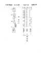
- FIG. 30 shows timing charts which show the operation of LBP in the eighth embodiment
- FIG. 31 is a drawing of characteristics that shows the relationship between the intensity of a laser beam and the electrostatic potential of a photosensitive drum
- FIG. 32 is a detailed perspective view of the font cartridge shown in FIGS. 25 and 26;
- FIG. 33 is a perspective view of another embodiment of a font cartridge
- FIG. 34 is a longitudinal sectional view of LBP in a sixth embodiment to which the present invention is applied.
- FIG. 35 is a perspective view of a further embodiment of a font cartridge
- FIG. 36 is a perspective view of another embodiment of a printer body.
- FIGS. 37a, 37b and 38 are drawings for illustrating of characteristics that show the relationship between the electrostatic potentials in a light portion and dark portion on a photosensitive drum and the stroke width.
- FIGS. 3 and 4 show a laser beam printer (LBP) to which the present invention is applied.
- LBP laser beam printer
- recording information of a character or a picture which is transmitted from a host computer and is converted into an electrical signal is input to an interface controller 1 where a recording signal is separated from it, the recording signal being converted into a driving signal suitable for driving a semiconductor laser 3 in a laser driving circuit 2 and then applied to a semiconductor laser 3.
- the semiconductor laser 3 is driven to an on or off state in correspondence with the driving signal, and the laser beam emitted is condensed by a collimeter lens 17 and deflected by being projected on a rotary polygon mirror 4 and then input to a f ⁇ lens 5 which serves to keep a given scanning speed on a photosensitive drum 8 and to an optical system (not shown) for correcting any deviation of the reflection angle of the reflection plane of the polygon mirror 4.
- a reflective mirror 6 After the laser beam has passed through the optical system and a reflective mirror 6, it is projected on the photosensitive drum 8 so as to scan it in the direction parallel to the rotational axis thereof.
- the photosensitive drum 8 is uniformly electrified by a primary electrostatic charger 7 and is then exposed to the laser beam.
- the charge in the portion of the photosensitive drum 8 to which the laser beam is applied is reduced, while the charge in the portion thereof to which the laser beam is not applied remains.
- An electrostatic latent image is consequently formed on the photosensitive drum 8 in correspondence with the on or off state of the laser 3.
- a toner (not shown) is then applied in correspondence with the electrostatic latent image from a developer 9 to form a toner image corresponding to the electrostatic latent image on the photosensitive drum 8.
- reference numeral 11 denotes a paper supply cassette, and transfer paper (not shown) extracted sheet one after another from the cassette by a paper supply roller 10 is sent to the photosensitive drum 8 synchronously with the developed image formed on the photosensitive drum 8 using a register roller 12.
- the transfer paper is brought into contact with the photosensitive drum 8 so that the toner image on the photosensitive drum 8 is transferred to the transfer paper by a transfer charger 13.
- the image on the transfer paper is fixed thereon by a fixer 14.
- any remaining developer is removed from the photosensitive drum 8 by a cleaner 15, and the photosensitive drum 8 is then uniformly exposed to light from a LED array 16 so that the remaining charge is removed for use in the next image forming process.
- the laser driving circuit 2 has a configuration such as that shown in FIG. 5 in which the image clock shown in FIG. 6 (B) which is generated from an image clock generating circuit 31 and a recording signal FIG. 6 (A) output from the interface controller 1 are applied to a comparator 32 for production of a driving signal FIG. 6 (C).
- the driving signal FIG. 6 (C) is amplified to a desired magnitude by a laser radiation circuit 33 and then applied to the laser 3.
- the recording signal obtained from the interface controller 1 is input to laser driving circuit 2, applied to the terminal 41 shown in FIG. 3 and then stored in a bit map memory 42.
- the bit map memory 42 has a capacity sufficient to store dot information corresponding to at least one page and allows for storage of the recording signal (shadowed in FIG. 7) therein.
- the contents of the memory 42 are subjected to discrimination by an arithmetic circuit 43 where the stroke width with the maximum frequency is calculated, and, when the stroke width of the line image on the bit map comprises n pixels in the longitudinal direction and m pixels in the lateral direction, the width d of the line image is defined by a lower of the values n and m.
- FIG. 8 shows the operational procedure of the arithmetic circuit 43.
- Steps S1 and S2 discrimination is conducted to determine whether or not a recording signal is present in the present addresses in the memory 42. If the address (1, 1) shown in FIG. 7 is the present address, the operation is returned to Step 1 in which the address is advanced by one since no signal is present therein, and the same operation as that described above is then performed. After the operation of this line has been completed, the address is advanced to the line 2. At the time the present address is (2, 2), the process is advanced to Step 3 since it is judged that there is a recording signal.
- Step 3 judgement is made as to whether or not a recording signal is present at the address above the present address in the same column.
- the present address is the address (2, 2)
- the operation is advanced to Step 4 since there is no recording signal at the address (1, 2) which is above the present address.
- the present address is the address (3, 2)
- the operation is returned to Step 1 in which the present address is advanced by one since there is a recording signal in the address (2, 2) above the present address.
- Step 4 the number of recording signals following the signal at the present address in the direction of the line are calculated, and the thus-calculated value is stored in a register MI provided in the arithmetic circuit 43.
- the present address is (2, 2) as shown in FIG. 7, the number, i.e., 7, of recording signals in the direction of the line is stored in the register MI.
- the operation then proceeds to Step 5 in which the number of recording signals in the downward direction of the column is then stored in the register Mc provided in the arithmetic circuit 43.
- Step 6 the operation is then advanced to Step 6 in which comparison is made between the numbers stored in the registers Ml and Mc, the smaller value being stored in a memory M in the arithmetic circuit 43.
- the value in the register Ml is judged to be smaller and stored in the memory M in Step 7
- the value in the register Mc is judged to be smaller and stored in the memory M in Step 8.
- the operation is then advanced to Step 9 in which judgement is made as to whether or not the processing for one page has been completed, and if not completed, the operation returns to Step 1 in which the address is advanced by one.
- Step 10 the operation is advanced to Step 10 in which the contents registered in the memory M (the memory corresponding to the histogram shown in FIG. 9) are checked and in which the number with the maximum frequency is calculated.
- This number is output to a high voltage transition controller (HVT) 44.
- HVT high voltage transition controller
- the dark portion voltage (VD) on the photosensitive drum 8 is so set as to be the highest value when the stroke width comprises one pixel and to be constant when the stroke width comprises 6 or more pixels.
- FIG. 11 shows the relationship between the stroke widths of the electrostatic latent image and the developed image on the photosensitive drum 8 when the control of the stroke width is performed as described above.
- V D denotes a dark portion voltage
- V L a light portion voltage
- V DC a development bias voltage which is a threshold value during development of the latent image.
- the stroke width (L,) of the developed image shown by the broken lines in FIG. 11 is generally greater than the ideal value (at 240 dip, the L, value of 3 pixel width is 410 ⁇ which is 129% of the ideal value 317 ⁇ ).
- the dark portion potential is determined by the stroke width d with the maximum frequency the average stroke width may be calculated, and the high voltage HV may, for example, be determined by this average stroke width.
- FIG. 13 shows a second embodiment of the present invention in which the development bias is controlled by using the stroke with the maximum frequency.
- a voltage -440 V is consequently applied as a development bias to the developer 9.
- FIG. 15 shows the relationship between the thusobtained developed image and the electrostatic latent image.
- the dark portion voltage V D is -700 V and the light portion voltage V L is ⁇ 100 V.
- the stroke width (L') is greater than the ideal width because a constant development bias V DC is applied regardless of the value of the stroke width, as in conventional methods, a stroke width (L) close to the ideal width is obtained by selecting the development bias V DC in correspondence with the stroke width.
- the curved position J1 of the E-J curve of the photosensitive drum 8 shown in FIG. 16 (the symbols shown in FIG. 16 represent the same as those in FIG. 11) must be used.
- the electrostatic charge conditions are changed as shown by T1 in FIG. 16 owing to the change in the environmental conditions, the light portion voltage V L is also changed.
- the curved portion of the E-J curve is generally easily affected by the deviation in the manufacturing lot of the photosensitive drum 8, and there is thus a tendency that the light portion voltage V L to becomes unstable.
- the substantially flat position J2 of the E-V curve shown in FIG. 16 can be used, the voltage (V L ) of the image portion is stable.
- the development bias is determined by the stroke width d with the maximum frequency, for example, and the development may be determined by using the average stroke width calculated for one page.
- FIG. 17 shows a third embodiment of the present invention in which the quantity of light emitted from the laser 3 is controlled in correspondence with the stroke width.
- the stroke width with the maximum occurrence is determined by using the memory 42 and the arithmetic circuit 43 in the same way as that employed in the first embodiment, and is input to a laser source controller 64.
- a laser source controller 64 To the controller 64 is applied the output from the image clock generating circuit 31 and the recording signal, through the delay circuit 66 and the output of the arithmetic circuit 43.
- the current for radiating laser is set in correspondence with the stroke width d with the maximum frequency, and the laser beam with a quantity of light corresponding to the current is applied to the photosensitive drum.
- the characteristic curve shown in FIG. 18 is stored in the form of a table in the controller 64 so that the radiation current is determined by using the table on the basis of the n value input therein.
- FIG. 19 shows the relationship between the stroke width of the developed image and the electrostatic latent image obtained in this embodiment.
- the stroke width is small, the stoke width L, obtained is greater than the ideal width if the electrostatic latent image is formed using a constant quantity of laser beam, as in conventional methods.
- the quantity of laser beam is controlled to be a small value, the stroke width L close to the ideal width can be obtained.
- FIG. 19 displays the degree to which the actual line width in the image deviates from the ideal line width as a percentage, as in FIG. 12. It is apparent that this is far closer to the ideal value than FIG. 1.
- the light intensity emitted from the laser is determined by the stroke width d with the maximum frequency, for example, and the quantity of light emitted may be determined by using the average stroke width calculated for one page.
- the laser output may be controlled by examining the number of pixels which form each line of individual characters or picture elements instead of recording with the same laser beam intensity over one page, as in the third embodiment.
- the information on one page is not stored in the memory 42, instead, a line memory (for example, for 6 lines) may be used.
- the number of scanning lines comprising of pixels to be stored is more that the number (in the above-described embodiment, 5) at which the stroke width deviates from the ideal value in.
- this line memory the number of contiguous pixels each line and column of each picture element which are components of the relevant image region is determined, and the smaller number is output to the laser source controller 64 so that the radiation current calculated by using the abovedescribed table is sent to the laser 3.
- the laser output may be uniformly set to a constant value (in the above-described embodiment, 1.5 mW).
- FIG. 21 shows a fourth embodiment in which the time for applying laser to one pixel is controlled in correspondence with the stroke width.
- the recording signal is stored in a memory 71 having a memory capacity of 6 lines, the number of contiguous pixels in each line and column of each of picture elements which are the components of the relevant image region are determined by the arithmetic circuit 72.
- the smaller number is applied to an image clock generation control circuit 73 in which a table representing the characteristic curve shown in FIG. 22 is stored so that a clock having a pulse length corresponding to the number of pixels forming the line image input therein is generated using the table.
- This clock is applied to a laser radiation circuit 74, the recording signal being applied to the laser 3 in correspondence with the pulse width of the clock.
- (A), (B) shows the recording signal and the laser driving signal which are so controlled that the laser radiation time is as short as 0.6 ⁇ S at a point G1 at which the recording signal does not continue, while the time is as long as 0.76 ⁇ S at a point G2 at which the recording signal continues.
- FIG. 24 shows the relationship between the stroke width of the developed image and the stroke width of the electrostatic latent image. It is found from the drawing that the stroke width L substantially the same as the ideal width can be obtained by reducing the length of one pulse (shown by the solid line), as compared with the stroke width L' obtained by radiating the laser with a constant pulse length regardless of the continuity of the recording signal (shown by the broken line). Although there is a possibility of deviation in the characteristic curve of the relationship between the value of current used for driving the laser and the laser output depending upon the laser chip used, the constant value of current for driving the laser can be used by controlling the driving time as in this embodiment. This embodiment has the advantage that the control can be performed in a stable state without being affected by deviation in the environment and the laser chip used.
- each of the embodiments use the arithmetic circuit as a means for determining the stroke width of the input signal
- the stroke width may be determined by using the numerical value which is input when the user uses a switch provided in the image forming device in correspondence with the quality of the image, in place of use of the output from the arithmetic circuit.
- the control is performed for each page and thus involves an advantage in that it can be realized at a lower cost.
- Each of the above-described embodiments concerns the control in such a manner that the stroke width is reduced as the number of pixels decreases, as well as image exposure in which the portion exposed to the laser beam is developed.
- the application of the present invention enables the stroke width to be so controlled as to be close to the ideal value.
- Each of the embodiments of the present invention can be applied to printers in which, for example, a fine character is printed with the ideal stroke width.
- reference numeral 170 denotes an LBP printer body, which can be used with the present invention and the image based on the recording signal supplied from a signal line 171 from an external character processing device is recorded on a recording paper supplied to the body 170 from a recording paper cassette 172.
- the recording paper on which the image has been completely recorded is discharged onto a taking-off tray 173.
- Reference numeral 129 denotes a font cartridge in which Gothic-type characters are stored. Therefore, when the recording signal contains a character code, the character code is recorded as the characters store in the font cartridge 129, e.g., a Gothic character, on the recording paper.
- the font cartridge 129 e.g., a Gothic character
- a plurality of font cartridges containing different types of characters are previously prepared, and the font cartridge which contains the necessary type of characters is mounted on the body, whereby any desired type of characters can be recorded in accordance with the demand of the operator.
- FIGS. 26 and 27 respectively show the recording unit and the laser beam deflection unit which are in the body 170.
- reference numeral 101 denotes a photosensitive drum serving as an image carrier which is uniformly electrified by a primary electrostatic charger 105.
- An electrostatic latent image is then formed on the photosensitive drum 101 by image exposure 106 using the laser beam modulated in correspondence with the recording signal.
- the electrostatic latent image is developed using the toner which adheres thereto by the electric field applied between the photosensitive drum 101 and a development sleeve 102 having a magnet 103.
- a recording paper 111.1 is introduced onto a transfer electrifier 107 by means of a transfer guide 111 and a transfer corona 110.
- the toner image formed on the photosensitive drum 101 is transferred onto the recording paper 111 1 by corona transfer provided on the rear side of the paper 111-1 from the transfer electrifier 107.
- the toner image transferred to the recording paper 111-1 is fixed onto the recording paper 111.1 by means of a fixing device (not shown).
- the toner and paper powder remaining untransferred on the photosensitive drum 101 are recovered by a cleaner 108.
- the charge remaining on the photosensitive drum 101 is removed by exposure using a pre. exposure lamp 109, and the photosensitive drum 101 is again used in the step subsequent to the primary electrostatic charge.
- the electric current passing through the photosensitive drum 101 electrified to -700 at the dark portion in the first electrification process and the potential of the portion exposed to the image exposure light 106 is reduced to the light portion potential -100 V.
- FIG. 27 is a perspective view of the deflection unit for the laser beam which is applied to the photosensitive drum.
- a repeated scanning movement is performed from the left to the right as viewed on the drawing using the laser beam 122 which is emitted from a semiconductor laser 121 and is reflected from a polygon mirror 124 which is caused to rotate by a motor 123.
- the laser beam reflected is passed through a f ⁇ lens 125 which is provided for the purpose of maintaining a constant scanning speed of the laser spot applied on the photosensitive drum 101. Other lenses are not shown in the drawing.
- the laser beam 122 is finally deflected by a mirror 126 and applied to the photosensitive drum 101 shown in FIG. 26.
- the beam is deflected by a mirror 127 which is disposed at the end of the width of scanning using the laser beam 122 and is received by a photodetector 128 which generates a synchronizing signal.
- a developer is provided with a development bias source 113a of a bias voltage A and a development bias source 113b of a bias voltage B one of which is selected by a switch 112.
- the switch 112 is switched so that the development bias A 113a is applied to the sleeve 102 from the bias source 113a.
- the development bias A113a is set to a dc component of -400 V, and in the case of reversal development, the contrast potential to the light portion potential is 300 V, whereby a thin line can be obtained.
- the development bias is switched by using the switch 112 so that a development bias B113b is applied to the sleeve 102.
- the development bias B113b is set to a dc component of -600 V, the contrast potential to the light portion potential is 500 V, whereby a thick line can be developed.
- FIG. 37(a) shows the relationship between the latent image potential and the development bias. It is possible to control the line width in such a manner that the line width for the Gothic type is GW and the line width for the Ming font is MW.
- the development bias value may be appropriately set in correspondence with the type of the character concerned.
- the development method in each of the above-described embodiments is based on a jumping development method.
- the switch 112 is so designed to be automatically switched on the basis of deciphering coded part 130 provided on the font cartridge 129 inserted into the body using a decoder 131.
- FIG. 32 shows in detail the coding unit 130 and the decoder 131 in which four projecting pieces 130a to 130d to be coded are provided at the predetermined positions on the cartridge 129 and push the four microswitches 131a to 131d comprising the decoder so as to change the "off" state to the "on” state. It is therefore possible to discriminate at most 16 types of font cartridges by coding the positions at which the projecting pieces are provided and the number thereof in correspondence with the type of the characters stored in the font cartridge.
- each font is developed with an appropriate thickness by changing the dc component of the development bias which is one of the development conditions.
- the width of a pattern may be optimized by changing the peak voltage V pp of the ac component or the frequency f or appropriately selecting the development conditions in combination thereof.
- the stroke width optimum of the font concerned is obtained by changing the development conditions
- a font image is recorded with a stroke width by changing the voltage applied to the primary electrifier 105 corresponding to the font of the character recorded.
- FIG. 34 shows such an embodiment in which either power source 105b of a voltage Vb or power source 105c of a voltage Vc is selected using a switch 105a which is switched using the output from the decoder 131.
- the members denoted by the same reference numerals as those shown in FIG. 26 has the same functions as those described in FIG. 26.
- the voltages Vb and Vc are switched in such a manner that the dark portion potential -700 V and the light portion potential 150 V are obtained when a Ming font is printed, and a dark portion potential -600 V and a light portion potential -100 V are obtained when a Gothic font is printed.
- the relationship between the latent image potential and the development bias is that shown in FIG. 38 in which the Ming font possesses a characteristic curve M, and the Gothic type possesses a characteristic curve G, the stroke widths formed being represented by Lm and Lg, respectively. It is thus possible to realize a stroke width in correspondence with each character font.
- the light portion potential may be changed in correspondence with the character font concerned, apart from the above-described embodiment.
- the voltages may be switched in such a manner that a dark portion potential -700 V and a light portion potential -150 V are obtained for a Ming type font, and a dark portion potential -700 V and a light portion potential -100 V are obtained for a Gothic type font.
- FIG. 28 shows an example in which the strength of the laser beam is selected under the stationary conditions of the development bias in the laser beam printer in the embodiment shown in FIG. 26 in correspondence with the type of the character font concerned.
- a voltage V1 or V2 is selectively applied to the semiconductor laser 121 from the power source 117 through the switch 116.
- the recording signal transmitted from the signal line 171 is applied to the semiconductor laser 121 through a driver 114 so that a source voltage is applied to the laser in correspondence with the recording signal. Since the strength of the laser beam depends upon the driving voltage, the strength of the laser beam can be controlled by controlling the discriminator 131 using the switch 116 in correspondence with the character font.
- the voltage V1 of the power source 117 is selected by the switch 116 and is applied to the semiconductor laser 121.
- the application of the voltage is turned on or off using the signal output from the driver 114 so that the laser is turned on or off.
- the photosensitive drum is exposed to the light with a quantity of 1.6 ⁇ J/cm 2 (an example), and the light portion potential on the photosensitive drum is -150 V, as shown in FIG. 31.
- the voltage V2 of the power source 117 is selected by the switch 116 and is applied to the laser 121.
- the photosensitive drum is exposed to light with a quantity of 2.28 ⁇ J/cm 2 (an example), and the light portion potential is -100 V, as shown in FIG. 31.
- FIG. 31 shows a characteristic curve LP which represents the relationship between the quantity of the laser beam applied and the potential of the photosensitive drum.
- the potential of the photosensitive drum can be controlled by controlling the strength of the laser beam applied thereto, as described above.
- the dc component of the development bias voltage is -500 V
- the ac component Vpp is 1600 V
- the frequency f 1800 Hz.
- FIG. 37(a) shows the characteristic curve M of the Ming font and the characteristic curve G of the Gothic font, as well as showing the change in the Gothic font stroke width GW and the Ming font stroke width MW produced when the light portion potential V L is changed by 50 V.
- FIG. 37(b) shows a characteristic curve representing the change in the stroke width when the development voltage V DC is changed, as well as showing that a Gothic-type stroke width GW and a Ming font stroke width MW can be obtained. It is found from these two drawings that the latent image potential has an effect on the stroke width which is greater than the development voltage.
- the other advantage is that there is no danger of positive fogging occurring.
- toner particles electrified to a low degree and electrified to the reverse polarity adhere to the dark portion on the photosensitive drum and thus cause fogging to appear on the image formed.
- the line concerned can be printed with a thickness conforming to the font by changing the thickness of the line.
- each of characters is recorded in the form of an assembly of dots, and the thickness of a line may be controlled to conform to the font thereof by changing the size of one dot by changing the light emission time of one dot.
- the recording signal is applied to the semiconductor laser 121 through a driver 114, and the voltage applied to a power source 117a is applied to the laser 121 in correspondence with the recording signal so that the semiconductor laser 121 can be driven in correspondence with the recording signal.
- To the driver 141 is applied a clock A or a clock B through a switch 118.
- the recording signal shown in FIG. 30a and the clock A shown in FIG. 30b are applied to the driver 141, the laser beam shown in FIG.
- the embodiment is therefore so configured that, if a Ming-type font cartridge is detected by the decoder 131, the clock A is selected, and if a Gothic-type font cartridge is detected by the decoder 131, the clock B is selected, whereby the thickness of a line can be controlled in correspondence with the relevant font.
- the method can be used within the region of the photosensitive drum where the light portion potential is saturated with a quantity of laser beam of 2.8 ⁇ J/cm 2 or more.
- This method is excellent with respect to its environmental stability and durability, as compared with the above-described method in which the thickness of a line is changed by using the laser power.
- the font cartridge 129a shown in FIG. 33 may be used in place of the font cartridge 129 used in the above-described embodiment.
- resistance 132 is provided on each font cartridge 129a so as to be connected to the pins 133 provided on the body side when mounted on the body 170.
- a supply source for the laser 121 is connected in series to the pins 133 so that the strength of the laser beam can be changed by changing the value of current passing through the laser using the resistance value thereof.
- the development conditions may also be changed by connecting the pins 133 provided on the body to the development bias source.
- the font cartridge 129b shown in FIG. 35 may be used in place of the font cartridge 129 used in the embodiment shown in FIG. 26.
- the font cartridge 129b four dip switches 134b may be provided in a portion thereof so that each of the switches is set to a given state corresponding to the type of the character font, the given state being incorporated into the body 120 through a connector (not shown).
- dip switches 134c are, like dip switches 134b not provided on a font cartridge 129c but are provided on a portion of a body 120, as shown in FIG. 36, so that information with respect to the character font can be input to the body in correspondence with the font cartridge used by setting the switches in correspondence with the character font.
- Such a method in which control data is read out enables the shapes of cartridge packages to be made uniform and thus has an advantage in that an attempt can be made to use a common cartridge.
- the mechanism since there is no need for use of the microswitch 131 on the body, the mechanism is simple, and the production cost can be reduced.
- control data used for determining the thickness of a line in correspondence with the character font may also be stored and read out by using the signal from the printer body or the host side of the printer to be used for controlling the printer.
- each of the above-described embodiments concerns LBP
- the present invention can also be applied to LED printers using an electrophotographic process in which emission of light from a plurality of LEDs which arranged in lines is controlled by using recording information on the basis of the same idea as that of each of the above described embodiments.
- the change of an electrophotographic process in correspondence with the type of the character font used enables an optimum stroke width corresponding to the type of each character font and thus the formation of a high quality character image.
Landscapes
- Physics & Mathematics (AREA)
- Engineering & Computer Science (AREA)
- General Physics & Mathematics (AREA)
- Optics & Photonics (AREA)
- General Engineering & Computer Science (AREA)
- Theoretical Computer Science (AREA)
- Microelectronics & Electronic Packaging (AREA)
- Plasma & Fusion (AREA)
- Control Or Security For Electrophotography (AREA)
Abstract
Description
Claims (58)
Applications Claiming Priority (4)
| Application Number | Priority Date | Filing Date | Title |
|---|---|---|---|
| JP63-111644 | 1988-05-10 | ||
| JP63-111645 | 1988-05-10 | ||
| JP63111645A JP2922518B2 (en) | 1988-05-10 | 1988-05-10 | Image forming device |
| JP63111644A JPH01282575A (en) | 1988-05-10 | 1988-05-10 | Image forming device |
Publications (1)
| Publication Number | Publication Date |
|---|---|
| US4965747A true US4965747A (en) | 1990-10-23 |
Family
ID=26450988
Family Applications (1)
| Application Number | Title | Priority Date | Filing Date |
|---|---|---|---|
| US07/347,923 Expired - Lifetime US4965747A (en) | 1988-05-10 | 1989-05-05 | Image forming apparatus |
Country Status (1)
| Country | Link |
|---|---|
| US (1) | US4965747A (en) |
Cited By (5)
| Publication number | Priority date | Publication date | Assignee | Title |
|---|---|---|---|---|
| US5731830A (en) * | 1993-09-14 | 1998-03-24 | Fujitsu Limited | Electrophotography recording method and recording apparatus using the method |
| US5850245A (en) * | 1994-12-07 | 1998-12-15 | Canon Kabushiki Kaisha | Page printer |
| US6229970B1 (en) * | 1995-10-25 | 2001-05-08 | Canon Kabushiki Kaisha | Image forming apparatus with an amount of use control feature and cartridge removably mounted on the apparatus |
| WO2008107297A1 (en) * | 2007-03-02 | 2008-09-12 | OCé PRINTING SYSTEMS GMBH | Method for printing and copying toner images onto a substrate material with reduction of the illumination in selected image elements |
| US20090002731A1 (en) * | 2002-08-28 | 2009-01-01 | Fuji Xerox Co., Ltd. | Image processing method and program therefor |
Citations (5)
| Publication number | Priority date | Publication date | Assignee | Title |
|---|---|---|---|---|
| JPS5681990A (en) * | 1979-12-06 | 1981-07-04 | Canon Inc | Edge intensifying device |
| US4387983A (en) * | 1979-07-03 | 1983-06-14 | Canon Kabushiki Kaisha | Scan type image recording apparatus |
| US4476474A (en) * | 1981-04-02 | 1984-10-09 | Canon Kabushiki Kaisha | Dot recording apparatus |
| US4517579A (en) * | 1979-09-20 | 1985-05-14 | Canon Kabushiki Kaisha | Electrostatic recording apparatus forming small non-recording regions in a recording field |
| US4816863A (en) * | 1986-11-25 | 1989-03-28 | E. I. Du Pont De Nemours And Company | Exposure control system for continuous tone electrophotographic film |
-
1989
- 1989-05-05 US US07/347,923 patent/US4965747A/en not_active Expired - Lifetime
Patent Citations (5)
| Publication number | Priority date | Publication date | Assignee | Title |
|---|---|---|---|---|
| US4387983A (en) * | 1979-07-03 | 1983-06-14 | Canon Kabushiki Kaisha | Scan type image recording apparatus |
| US4517579A (en) * | 1979-09-20 | 1985-05-14 | Canon Kabushiki Kaisha | Electrostatic recording apparatus forming small non-recording regions in a recording field |
| JPS5681990A (en) * | 1979-12-06 | 1981-07-04 | Canon Inc | Edge intensifying device |
| US4476474A (en) * | 1981-04-02 | 1984-10-09 | Canon Kabushiki Kaisha | Dot recording apparatus |
| US4816863A (en) * | 1986-11-25 | 1989-03-28 | E. I. Du Pont De Nemours And Company | Exposure control system for continuous tone electrophotographic film |
Cited By (6)
| Publication number | Priority date | Publication date | Assignee | Title |
|---|---|---|---|---|
| US5731830A (en) * | 1993-09-14 | 1998-03-24 | Fujitsu Limited | Electrophotography recording method and recording apparatus using the method |
| US5850245A (en) * | 1994-12-07 | 1998-12-15 | Canon Kabushiki Kaisha | Page printer |
| US6229970B1 (en) * | 1995-10-25 | 2001-05-08 | Canon Kabushiki Kaisha | Image forming apparatus with an amount of use control feature and cartridge removably mounted on the apparatus |
| US20090002731A1 (en) * | 2002-08-28 | 2009-01-01 | Fuji Xerox Co., Ltd. | Image processing method and program therefor |
| US7953302B2 (en) * | 2002-08-28 | 2011-05-31 | Fuji Xerox Co., Ltd. | Image processing method and image processing computer program |
| WO2008107297A1 (en) * | 2007-03-02 | 2008-09-12 | OCé PRINTING SYSTEMS GMBH | Method for printing and copying toner images onto a substrate material with reduction of the illumination in selected image elements |
Similar Documents
| Publication | Publication Date | Title |
|---|---|---|
| US4046471A (en) | Dual mode electrophotographic apparatus having dual function printing beam | |
| US4467334A (en) | Laser beam printer | |
| US4460909A (en) | Method and apparatus for enhancing the resolution of an electrophotographic printer | |
| US4201994A (en) | Information formation apparatus | |
| EP0246457B1 (en) | Compensation for fine line prints | |
| US4241415A (en) | Masking device for selectively preventing visualization of data from a data output system | |
| EP0422602A2 (en) | Method of and apparatus for recording color image | |
| US5128699A (en) | Image recording apparatus capable of changing dot density and dot size | |
| US4965747A (en) | Image forming apparatus | |
| US5187495A (en) | Image forming apparatus for obtaining image upon scanning with laser beam | |
| US5353048A (en) | Image recording apparatus | |
| US5428434A (en) | Flash-radiation type toner image fixing device | |
| US5412408A (en) | Beam recording apparatus with intensity control | |
| JPS592025B2 (en) | Kiroku Fukushiya Souchi | |
| JP2922518B2 (en) | Image forming device | |
| US5493325A (en) | Graduation reproduction in optical recording | |
| EP1059804A2 (en) | Apparatus and method for forming image with high image reproducibility | |
| JPH0784072B2 (en) | Image recorder | |
| EP0825495B1 (en) | Electrophotographic recording device | |
| JPH10239980A (en) | Method for detecting amount of remaining developer, image forming device, and process cartridge | |
| JPS60112474A (en) | Japanese character outputting device | |
| US5737008A (en) | Electrophotographic image recording apparatus with photoreceptor exposure control | |
| JP2985234B2 (en) | Electrophotographic image forming equipment | |
| JP2825953B2 (en) | Laser printer | |
| JPS63146568A (en) | Digital copying machine |
Legal Events
| Date | Code | Title | Description |
|---|---|---|---|
| AS | Assignment |
Owner name: CANON KABUSHIKI KAISHA, A CORP. OF JAPAN, JAPAN Free format text: ASSIGNMENT OF ASSIGNORS INTEREST.;ASSIGNORS:OHTSUKA, YASUMASA;HASEGAWA, HIROTO;TANIGAWA, KOICHI;REEL/FRAME:005082/0872 Effective date: 19890414 |
|
| STCF | Information on status: patent grant |
Free format text: PATENTED CASE |
|
| CC | Certificate of correction | ||
| FEPP | Fee payment procedure |
Free format text: PAYOR NUMBER ASSIGNED (ORIGINAL EVENT CODE: ASPN); ENTITY STATUS OF PATENT OWNER: LARGE ENTITY |
|
| FPAY | Fee payment |
Year of fee payment: 4 |
|
| FPAY | Fee payment |
Year of fee payment: 8 |
|
| FEPP | Fee payment procedure |
Free format text: PAYOR NUMBER ASSIGNED (ORIGINAL EVENT CODE: ASPN); ENTITY STATUS OF PATENT OWNER: LARGE ENTITY Free format text: PAYER NUMBER DE-ASSIGNED (ORIGINAL EVENT CODE: RMPN); ENTITY STATUS OF PATENT OWNER: LARGE ENTITY |
|
| FPAY | Fee payment |
Year of fee payment: 12 |