US4965635A - Digitizer apparatus and method - Google Patents
Digitizer apparatus and method Download PDFInfo
- Publication number
- US4965635A US4965635A US07/365,332 US36533289A US4965635A US 4965635 A US4965635 A US 4965635A US 36533289 A US36533289 A US 36533289A US 4965635 A US4965635 A US 4965635A
- Authority
- US
- United States
- Prior art keywords
- image
- original
- reproduction
- pattern
- toner
- Prior art date
- Legal status (The legal status is an assumption and is not a legal conclusion. Google has not performed a legal analysis and makes no representation as to the accuracy of the status listed.)
- Expired - Fee Related
Links
Images


Classifications
-
- G—PHYSICS
- G03—PHOTOGRAPHY; CINEMATOGRAPHY; ANALOGOUS TECHNIQUES USING WAVES OTHER THAN OPTICAL WAVES; ELECTROGRAPHY; HOLOGRAPHY
- G03G—ELECTROGRAPHY; ELECTROPHOTOGRAPHY; MAGNETOGRAPHY
- G03G15/00—Apparatus for electrographic processes using a charge pattern
- G03G15/04—Apparatus for electrographic processes using a charge pattern for exposing, i.e. imagewise exposure by optically projecting the original image on a photoconductive recording material
- G03G15/04018—Image composition, e.g. adding or superposing informations on the original image
-
- G—PHYSICS
- G03—PHOTOGRAPHY; CINEMATOGRAPHY; ANALOGOUS TECHNIQUES USING WAVES OTHER THAN OPTICAL WAVES; ELECTROGRAPHY; HOLOGRAPHY
- G03G—ELECTROGRAPHY; ELECTROPHOTOGRAPHY; MAGNETOGRAPHY
- G03G15/00—Apparatus for electrographic processes using a charge pattern
- G03G15/01—Apparatus for electrographic processes using a charge pattern for producing multicoloured copies
-
- G—PHYSICS
- G03—PHOTOGRAPHY; CINEMATOGRAPHY; ANALOGOUS TECHNIQUES USING WAVES OTHER THAN OPTICAL WAVES; ELECTROGRAPHY; HOLOGRAPHY
- G03G—ELECTROGRAPHY; ELECTROPHOTOGRAPHY; MAGNETOGRAPHY
- G03G15/00—Apparatus for electrographic processes using a charge pattern
- G03G15/36—Editing, i.e. producing a composite image by copying one or more original images or parts thereof
Definitions
- the present invention relates to reproduction apparatus and methods and more specifically to apparatus and methods for digitizing or identifying areas of documents for special treatment when reproducing same.
- a method and apparatus for reproducing documents employing a reproduction apparatus having a function for selective area treatment by digitizing a document to identify an area thereof for selective treatment.
- the original document is reproduced so that machine readable patterns are produced thereon to assist in defining area(s) selected for special treatment; and further reproductions are then made with selected area treatment.
- FIG. 1a is a sketch of an original document, D, to be reproduced and also a reproduction, R, thereof with a grid pattern added thereto to provide a machine readable grid for use in digitizing an area(s) thereof for selective area treatment;
- FIG. 1b is a sketch of an alternative embodiment showing a reproduction R 2 with a grid pattern G 2 whose lines are at a 45 degree angle with the edges of the page.
- FIGS. 2a and 2b are respective sketches shown greatly enlarged of reproductions R' and R" with machine readable and operator readable data added thereto for use in digitizing areas thereof for selective area treatment;
- FIG. 3 is a perspective view of one embodiment of electrophotographic apparatus for practice of the present invention.
- FIG. 4 is a schematic front elevational view of the apparatus of FIG. 3 and showing the general arrangement of electrophotographic reproduction apparatus that is in accordance with the invention
- FIG. 5 is a schematic illustrating a data input station and block diagrams of controls for controlling the apparatus shown in FIG. 4;
- FIG. 6 is a schematic of a cross-section of a digitizing wand for use with one embodiment of the method and apparatus of the invention
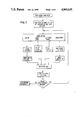
- FIG. 7 is a flowchart illustrating the steps for operator selection of selective area treatments in accordance with the invention.
- FIG. 8 is a schematic of another digitizing wand for use with the methods and apparatus of the invention.
- the original document D includes a continuous tone pictorial area P and other areas containing line-type information LT.
- the original document D includes a continuous tone pictorial area P and other areas containing line-type information LT.
- a reproduction R is made of the original document D.
- the reproduction R includes a machine readable grid G in addition to the pictorial area P and line-type information LT.
- the reproduction is made using the electrophotographic reproduction apparatus of FIGS. 3-5.
- An electrophotographic reproduction apparatus 100 includes a photoconductive web 105 that is trained about six transport rollers 110, 111, 112, 113, 114 and 115, thereby forming an endless or continuous web.
- Roller 113 is coupled to a drive motor Ml in a conventional manner.
- Motor Ml is connected to a source of potential when a switch (not shown) is closed by a logic and control unit (LCU) 131.
- LCU logic and control unit
- a charging station 117 is provided at which the photoconductive surface 109 of the web 105 is sensitized by applying to such surface a uniform electrostatic primary charge of a predetermined voltage.
- the station 117 includes an A.C. corona charger.
- the output of the charger is controlled by a grid 117a connected to a programmable power supply 117b.
- the supply 117b is in turn controlled by the LCU 131 to adjust the voltage level Vo applied onto the surface 109 by the charger 117.
- a light image of a document sheet D is projected by mirrors 106, 108 and lens 107 onto the photoconductive surface 109 of the web 105. While the apparatus will be described with respect to reflection exposure of the original document sheet onto the photoconductive surface, the use of transmission exposures of an original is also contemplated by the invention.
- the projected image dissipates the electrostatic charge at the light exposure areas of the photoconductive surface 109 and forms a latent electrostatic image.
- a programmable power supply 118a under the supervision of the LCU 131, controls the intensity or duration of light from flash lamps 103 and 104 to adjust the exposure level E incident upon the web 105.
- Two development stations 119a and 119b are provided.
- Each includes developer which may consist of iron carrier particles and electroscopic toner particles with an electrostatic charge opposite to that of the latent electrostatic image. Developer is brushed over the photoconductive surface 109 of the web 105 and toner particles adhere to the latent electrostatic image to form a visible toner particle, transferable image.
- the development station may be of the magnetic brush type with one or two rollers.
- One developer station 119b includes non-magnetic toner particles
- the other station 119a includes metal containing toner particles such as the known MICR toner particles which are characterized by magnetic properties, i.e., these particles have a permeability to magnetic fields and are thus able to be detected by magnetic detectors.
- a suitable electrical bias to the station is provided by a programmable power supply 119d.
- Back-up rollers or the like 119c and 119e are provided and associated with a respective development station and selectively activated by LCU 131 to control which development station is to apply toner to the web 105.
- the apparatus 100 also includes a transfer station 121 shown as a corona charger 121a at which the toner image on web 105 is transferred to a copy sheet S; and a cleaning station 125, at which the photoconductive surface 109 of the web is cleaned of any residual toner particles remaining after the toner images have been transferred.
- a transfer station 121 shown as a corona charger 121a at which the toner image on web 105 is transferred to a copy sheet S
- a cleaning station 125 at which the photoconductive surface 109 of the web is cleaned of any residual toner particles remaining after the toner images have been transferred.
- a copy sheet S is fed from a supply 123 by a roller 126.
- the copy sheet may then be driven by continuous driven rollers (not shown) which then urge the sheet against a suitable registration mechanism (not shown).
- the copy sheet is then released and moves forward onto the web 105 in alignment with a toner image at the transfer station 121.
- the web has a plurality of perforations along one of its edges. These perforations generally are spaced equidistantly along the edge of the web 105.
- the web 105 may be divided into six image areas or image frames by F perforations, and each image area may be subdivided into 51 sections by C perforations.
- F and C perforations to the image areas is disclosed in detail in commonly assigned U.S. Pat. No. 3,914,047 filed in the name of Hunt, Jr. et al and issued Oct. 21, 1975.
- suitable means 130 for sensing web perforations.
- This sensing produces input signals into the LCU 131 which has a digital computer, preferably a micoprocessor.
- the microprocessor has a stored program responsive to the input signals for sequentially actuating then deactuating the work stations as well as for controlling the operation of many other machine functions as disclosed in U.S. Pat. No. 3,914,047.
- Additional encoding means 160 may be provided as known in the art for providing more precise timing signals for control of the various functions of the apparatus 100.
- FIG. 5 a block diagram of logic and control unit (LCU) 131 is shown which interfaces with the apparatus 100.
- a document feeding apparatus (not shown) may also be provided that includes known recirculating feeder and document positioner means. Details of a known document feeding apparatus may be found, for example, in U.S. Pat. No. 4,451,137, issued May 29, 1984 in the name of Farley.
- the LCU 131 consists of temporary data storage memory 132, central processing unit 133, timing and cycle control unit 134 and stored program control 136. Data input and output is performed sequentially under program control. Input data are supplied either through input signal buffers 140 to an input data processor 142 or to interrupt signal processor 144. The input signals are derived from various switches, sensors and analog-to-digital converters. The output data and control signals are applied to storage latches 146 which provide inputs to suitable output drivers 148, directly coupled to leads. These leads are connected to the various work stations, mechanisms and controlled components associated with the apparatus. An electrical power supply (not shown) is provided to power the LCU 131.
- FIG. 5 Also shown in FIG. 5 is an operator control panel CP.
- PRINT for initiating normal copying
- other keys 177 are provided for designating the number of copies.
- a grid print button 65 is provided for initiating a copying mode to be described for reproducing a reproduction R (FIG. 2b) from a normal original document D.
- a special print button 66 is also provided for initiating a special print operation wherein a selective area treatment is to be provided during reproduction.
- Document sheet D includes continuous tone pictorial information (or more generally--information to be reproduced with the selective screening process described herein) in the area defined by rectangle a,b,c and d and line-type information LT (such as alphanumerics, or generally information not to be reproduced with the selective screening process described herein) in the background areas.
- pictorial information or more generally--information to be reproduced with the selective screening process described herein
- line-type information LT such as alphanumerics, or generally information not to be reproduced with the selective screening process described herein
- the "GRID PRINT" button 65 on the control is used by the operator to initiate a special copying operation wherein a reproduction R of the document D is made with a grid pattern superimposed upon the information reproduced from the original.
- the original document, D is placed face down upon the transparent glass exposure platen 102 in register with say a reference such as a corner of the platen.
- the copier grid print button 65 is then pressed and an optical exposure of an image frame of the electrically charged photoconductor 105 made by activating exposure lamps 103, 104.
- an exposure of a grid pattern is made upon an adjacent image frame using an LED (light emitting diode) printhead 192.
- a program stored in stored program control 136 includes data for printing the grid pattern upon this adjacent image frame of web 105.
- the adjacent frame thus has its uniform charge modulated so that the charge remaining after exposure in the LED printhead represents a latent electrostatic image of a grid.
- the latent image of the grid is developed with the MICR toner in station 119a.
- the lamps 103, 104 are activated for making the exposure of the image on document D onto the next image frame.
- This image frame is also developed but with the non-metallic toner in station 119b.
- the two developed image frames are then transferred in register to the copy sheet S using transfer charger 121a to transfer the toner image of the grid to sheet S; transfer vacuum roller 121c, upon which the sheet circulates until in register with the next image frame; and transfer charger 121b, which transfers a reproduction of the image present on original document D to the copy sheet.
- the registered images are then transported by vacuum belt 165 to fuser rollers 127 which fix the images upon the copy sheet.
- a reproduction R is formed similar to that indicated in FIG. 1 and transported to output tray 170.
- the operator may now take a digitizing wand and the reproduction R to a convenient location and identify the location(s) on the reproduction R of the area(s) selected for special treatment and the type(s) of special treatment desired for respective areas, i.e., selective screening, accent color, selective erase, selective annotation.
- wand 194 includes an ink-containing pen 210 that is biased by spring 212 in the direction shown by arrow B.
- a switch 214 is closed which energizes a magnetic detection unit 216 in the wand.
- the head may comprise magnetic write and read units, the write unit impressing a magnetic polarization to the grid lines with the read unit adapted to detect same.
- the head may comprise a detection unit for detecting changes in magnetic permeability.
- the wand In order to digitize or identify a point, the wand is placed at the top reference edge 25 of the reproduction R and the pen-point thereof moved over the sheet R along a vertical grid line in a direction parallel to a side reference edge 35. For example, with reference to FIG. 5 to digitize point "a" on reproduction sheet R, the wand 194 is moved from the reference edge 25 parallel to reference edge 35 until point "a" on sheet D is reached. In response to the magnetic detection portion of the wand traversing the horizontal magnetic grid lines on the reproduction R, pulses are generated and sent to the digitizer's logic electronics which counts the number of pulses and translates same into Y 1 , one of the two coordinates for point "a".
- the other coordinate is determined similarly but by moving the wand from reference edge 35 parallel to reference edge 25 until point "a" is again reached.
- the pulses created determines the coordinate, X l .
- the location of point "a” is thus identified.
- each of the other coordinates requiring digitization or determination as to location relative to the corner reference is made.
- the other points, b, c and d may be defined by movement of the wand along the perimeter of the rectangle to be formed in accordance with a prescribed protocol.
- the grid pattern may be distinguishable in the x and y directions by having the frequency of the grid lines be different in the different directions.
- the magnetic grid pattern may be 2 lines/inch in one direction and 4 lines/inch in the other direction.
- the circuitry in digitizer 196 for translating the electrical pulse signals into coordinate data can determine directionality by discriminating the frequency of the pulses.
- changes in direction of movement of the wand are determined and a corner point of the rectangle defined at the location of the change of direction.
- the digitizer circuitry for detecting the points defined by the rectangle may comprise a pulse shaper and amplifier 221 for amplifying the pulse signals from the detection unit 216, a frequency discriminator 218 which senses the amplified pulses from the pulse shaper and generates a one-bit digital signal indicative of the frequency of the pulses; i.e., are the current pulses high or low, and thus indicative of direction of movement of the wand and a microcomputer 222 which is programmed to count the pulses from the amplified pulses and which receives the one-bit directional signal. Those signals are used by the computer to determine the positions of the various vertices of rectangle abcd. Power for the head is provided by a battery 224.
- the wand may be used to identify this area at the four corner points of this area.
- the points are identified in an order such that a straight line joints adjacent points as in the order a,b,c, and d to define a rectangle.
- the computer control for the digitizing tablet may also be programmed to accept inputs of area data to define other geometrical shapes such as circles.
- the microcomputer 222 for the digitizing wand is programmed to recognize that the area is bordered by the straight lines joining adjacent points a, b, c, and d and the coordinates for the area to be selectively screened can be thus calculated and stored in temporary memory residing on the microcomputer.
- the coordinates for the points a, b, c and d would be x 1 , y 1 ; x 2 , y 1 ; x 2 , y 2 ; and x 1 , y 2 , respectively.
- two diagonal corner points may be used to define the rectangle.
- the operator Prior to or after identifying the area to receive selective area treatment the operator will also select the function desired such as selective screening which is selected by depressing the input function button 58 which is on the wand. A signal is generated and stored in the memory on the microcomputer 222 that this is the selected area treatment to be performed. A buffer 219 may be provided to temporarily store signals from the button switches and feed them to the microcomputer 222 when requested. Further identification of the area may be made with use of the "IN” and "OUT” buttons 60, 61 with “IN” defining the treatment to be everywhere outside the area defined. Alternatively, the "IN” button may be deleted and the computer programmed to accept “IN” as a default condition unless “OUT” is otherwise selected.
- a format input button 57 may also be provided to allow the operator to designate the size of the reproduction R, i.e., 81/2" ⁇ 11" or 11" ⁇ 14" by traversing the wand from one edge to the opposite edge and counting the pulses to determine each dimension.
- the reproduction R may have an imprinted reference spot that is recorded with the grid during the reproduction process and the location of points a, b, c and d made relative to this reference spot.
- the operator may repeat this operation for additional areas to be specifically treated for reproduction of this document. Assuming this information is input, the operator then places the wand into the copier in the recess 74 provided therefor. With the wand selected properly within the recess plug terminals 68 engage a complimentary socket in the copier recess and the information stored on the wand is downloaded to the copier's logic and control unit 131.
- the ICU 131 processes this data and outputs same to the display screen 153 which displays the selection.
- the operator then takes the original document D and places same face down in a registered position upon the exposure platen 102.
- Suitable logic or computing means may be provided in the digitizer or LCU 131 to translate the data points determined during the digitizing step for a plane formed by axes X, Y in the plane of the reproduction R to that of X', Y' on an image frame of the photoconductor's surface 109.
- image exposure is effected by flash lamps 103 and 104, which form a latent electrostatic image of the document sheet upon an image frame of the web. Formation of a plurality of charge islands within the latent electrostatic image is effected by a second exposure upon the web by an LED printhead 192.
- This second exposure may be carried out prior to, simultaneous with, or after image exposure of the photoconductor, the only requirement being that this second exposure be carried out after charging by primary charger 17 and prior to development.
- the printhead 192 for simulating a screen-like exposure upon the web.
- the printhead 192 comprises a plurality of light-emitting diodes (LED's) arranged in a row. These LED's are coupled to the output drivers 148 of the LCU 131.
- Optical fibers are associated with the LED's for imaging light from the LED's onto the photoconductor. Such fibers may be arranged as a conventional gradient index lens array (GRIN) 197, such as a SELFOC (trademark of Nippon Sheet Glass Co., Ltd.) array.
- GRIN gradient index lens array
- the LCU calculates which of the LED's to illuminate and the duration of such exposure.
- the portions of the printhead between the ordinates y" 1 , y" 2 on the Y" axis of the linear printhead correspond to their respective counterparts on the original document and to their respective ordinate counterparts y' 1 , y' 2 and on the y' axis of the image frame.
- These ordinate pairs each define a transverse line past which the respective latent electrostatic continuous tone image area on the photoconductor will be imaged.
- the appropriate LED's are illuminated by the LCU.
- the illumination provided by the selected LED's is created by a series of pulses to them so that light from the LED's forms a simulated screen pattern upon the area of the image frame corresponding to rectangle a,b,c and d.
- the parameters for determining the timing of when to commence pulsing of the LED's and when to terminate same are provided by the abscissa pairs x' 2 , x' 1 of the image frame, respectively.
- the LED's providing illumination between y" 1 and y" 2 commence to be rapidly pulsed. This pulsing lasts until the transverse line x' 1 (also determined by the LCU passes by the printhead.
- a latent electrostatic image of a screen pattern is imaged upon the charged web by the second exposure source substantially only in the area of the image frame upon which the continuous tone image is to appear and, importantly, no screened exposure is provided outside of this area.
- the image of the document D is subsequently in this example superimposed upon the same image frame by activation of flashlamps 103, 104 to further modulate the electrostatic charge.
- the charged image pattern is then developed with the appropriate colored toner by actuation of the back-up roller 119e of developer station 119b, and the developed image from transformed to a receiver sheet S' as described above. There is thus provided a reproduction with an area thereof that has been selectively treated vis-a-vis that of the original.
- an area of the document is designated and the erase source such as an LED eraser or printer, used to expose selected areas of the electrostatically charged photoconductor's image frame used to reproduce this document. These areas generally border the image area(s) that is to be saved and do not receive toner when the image frame is developed.
- the respective button 62 on the wand and labelled “ERASE” is used for selecting this option as well as buttons labelled "IN” or "OUT” for identifying the area to be erased; i.e., is the area to be erased within or without the area selected.
- the appropriate LED's are driven so that their exposures overlap to erase charge completely or at least to a level below which development can occur in those areas to be erased.
- two image frames may be employed with the copier having two development stations with different colored toners.
- the original is exposed onto the two image frames and the LED printhead erases selected areas from each image frame.
- the unerased areas in each image frame are developed with respective colored toners and the developed two image frames transferred in register to the same surface of a copy sheet.
- the copier may be provided with a third station having toner of a different color from the other stations.
- the MICR toner station may be removed and an accent color station inserted or one station may be an accent color station and the other station carrying MICR toner may serve as the normal black toner station.
- an area of an original may be blocked from the optical exposure and selected information written by the LED printhead into the area of the photoconductor's image frame that has been blocked.
- An electronic data generator 152 may be provided to supply the data signals to be printed.
- a masking 192b may be moved into the optical exposure path either by operation of a solenoid or motor in response to signals from the LCU 131.
- the grid pattern G2 of magnetic toner is reproduced so that the lines thereof are all parallel and at an angle of 45 degrees with the edges of the page.
- the magnetic detection unit will respond to movement over this page when moved parallel to the edges of the page in accordance with a predetermined protocol for movement.
- an electro-optical source such as an LED printhead or laser or other device wherein the selective area treatment is accomplished by modifying the data that is printed by the electro-optical source.
- the invention in its broader aspects, is not limited to electrophotography, but may also find utility in other applications where selective reproduction is desired for example, ink jet, thermal printing, etc. wherein the original image of the document is electronically scanned and only a selected area printed based upon inputs provided by the operator during the digitizing process.
- the invention has been described with reference to forming a reproduction of an original and printing thereon a magnetic grid pattern; however, in its broader aspects other sheets such as those that may be optically detected may also be suitable with a corresponding change in the sensor unit to a photosensor or the like.
- an original document, D is to be reproduced with selective area treatment reproduced in a grid print mode as described above except in this mode the grid has a code printed into it, i.e., each point of the grid may be read to define that point without resort to movement from a side edge.
- each point 250 may have its own bar code or microcode that identifies the coordinates of that grid point.
- the bar code may be magnetic or optical. In its preferred form, it is optical either as a bar code or character code. This code is printed by the LED printhead 192 during a grid print reproduction of document D when forming of reproduction R'.
- the code can be formed in a different color than that used to reproduce the information of document D onto reproduction, R'. This color differentiation allows the wand is distinguish between the original information and the coded information by being biased to be sensitive to one color. It may be desirable to add a UV fluorescent compound to one of the color stations to facilitate reading of the code by a UV light source on the wand. Alternatively, where only one toner station is present, the code may be read in an adjacent area wheren no print is present representing information from the original document, D. Usually the major portion of a document is white background and the printed area of an original constitutes only a small part of the area. There will thus be many points adjacent a printed area that will not be covered with information from the original.
- the wand 200 includes a light source 210 which directs light at the point to be digitized.
- a lens such as a Selfoc lens 211 may then focus the reflection from this point to a photosensor such as a CCD array 220.
- the array 220 is driven by a driver 230 and the signals from the array 220 are fed to an analog/digital converter 240 and then input to a microcomputer 241.
- the computer includes a program to translate this code into a set of coordinate point which are stored in buffer memory 245.
- a battery pack 242 provides the electrical energy required for this operation.
- the contents of the buffer memory may be downloaded via terminals 243 to the copier when placed in a recess on the copier similar to recess 74 as described above.
- the wand 200 also includes the function selection buttons 260-266 as described for wand 194.
- An additional button 246 may be provided to produce a signal to the microcomputer to initiate a reading of a point. This is in lieu of the pressure sensitive pen point described for wand 194.
- the code reproduced is visually readable and digitization may be provided without a wand.
- the visual code is printed upon a reproduction R" when the grid button is pressed and original document, D, located in a registered position on the platen.
- the code is printed by the printhead 192 in response to signals from the data generator 152.
- the code is printed on one image frame and the document, D, reproduced on a second image frame.
- the two image frames may be developed with the same or different colored toners and transferred in register onto a copy sheet to form the reproduction R".
- the control panel CP will have a key pad 177 allowing an operator to identify the coordinates by pressing appropriate buttons.
- 2b may be represented by coordinates 70, 40. These numbers may be input by the operator into the key pad 177.
- the LCU 131 then operates the copier 100 to provide the desired selective area treatment which have been input by the operator through the same key pad buttons on the control panel CP. By pressing a star button * on the key pad the LCU 131 will now accept a numerical input as a code for a particular selective area treatment. The reproduction with selective treatment will then be made in accordance with techniques described above.
- the reproduction of the original document, D, on R" may be made relatively lighter so that it is visible but not obscuring of grid code information.
- electrophotographic reproduction apparatus is shown as an optical copier
- the invention may be practiced with electronic copiers wherein the original document is scanned electronically and then printed.
- a scanner that may include a CCD device is provided that "reads" the level of grey on the original line by line. This information is then processed, stored in memory, and printed out onto the appropriate image frame by an electronic printer such as the LED printhead 192 or laser printer.
- the digitizing data may be combined electronically with the data representing the image signals of document D, to be processed together electronically. Since the data on the original document may be stored electronically in a memory, the step of reproducing the original with selective area treatment may be accomplished without the need to scan the original a second time.
Abstract
Description
Claims (13)
Priority Applications (1)
| Application Number | Priority Date | Filing Date | Title |
|---|---|---|---|
| US07/365,332 US4965635A (en) | 1989-06-13 | 1989-06-13 | Digitizer apparatus and method |
Applications Claiming Priority (1)
| Application Number | Priority Date | Filing Date | Title |
|---|---|---|---|
| US07/365,332 US4965635A (en) | 1989-06-13 | 1989-06-13 | Digitizer apparatus and method |
Publications (1)
| Publication Number | Publication Date |
|---|---|
| US4965635A true US4965635A (en) | 1990-10-23 |
Family
ID=23438422
Family Applications (1)
| Application Number | Title | Priority Date | Filing Date |
|---|---|---|---|
| US07/365,332 Expired - Fee Related US4965635A (en) | 1989-06-13 | 1989-06-13 | Digitizer apparatus and method |
Country Status (1)
| Country | Link |
|---|---|
| US (1) | US4965635A (en) |
Cited By (13)
| Publication number | Priority date | Publication date | Assignee | Title |
|---|---|---|---|---|
| US5038169A (en) * | 1990-09-28 | 1991-08-06 | Xerox Corporation | Plural mode printer user interface terminal |
| US5314829A (en) * | 1992-12-18 | 1994-05-24 | California Institute Of Technology | Method for imaging informational biological molecules on a semiconductor substrate |
| US5373350A (en) * | 1992-05-01 | 1994-12-13 | Xerox Corporation | Xerographic/thermal ink jet combined printing |
| US6025862A (en) * | 1995-01-03 | 2000-02-15 | Eastman Kodak Company | Accent color image forming method and apparatus |
| US6100877A (en) * | 1998-05-14 | 2000-08-08 | Virtual Ink, Corp. | Method for calibrating a transcription system |
| US6111565A (en) * | 1998-05-14 | 2000-08-29 | Virtual Ink Corp. | Stylus for use with transcription system |
| US6124847A (en) * | 1998-05-14 | 2000-09-26 | Virtual Ink, Corp. | Collapsible detector assembly |
| US6147681A (en) * | 1998-05-14 | 2000-11-14 | Virtual Ink, Corp. | Detector for use in a transcription system |
| US6177927B1 (en) | 1998-05-14 | 2001-01-23 | Virtual Ink Corp. | Transcription system kit |
| US6191778B1 (en) | 1998-05-14 | 2001-02-20 | Virtual Ink Corp. | Transcription system kit for forming composite images |
| US6211863B1 (en) | 1998-05-14 | 2001-04-03 | Virtual Ink. Corp. | Method and software for enabling use of transcription system as a mouse |
| US6310615B1 (en) | 1998-05-14 | 2001-10-30 | Virtual Ink Corporation | Dual mode eraser |
| US20020054026A1 (en) * | 2000-04-17 | 2002-05-09 | Bradley Stevenson | Synchronized transmission of recorded writing data with audio |
Citations (5)
| Publication number | Priority date | Publication date | Assignee | Title |
|---|---|---|---|---|
| US4343540A (en) * | 1981-02-17 | 1982-08-10 | The Gerber Scientific Instrument Company | Plotting apparatus and method utilizing encoded optical means |
| US4740818A (en) * | 1985-12-16 | 1988-04-26 | Eastman Kodak Company | Electrophotographic reproduction apparatus and method with selective screening |
| US4814552A (en) * | 1987-12-02 | 1989-03-21 | Xerox Corporation | Ultrasound position input device |
| US4862219A (en) * | 1985-02-21 | 1989-08-29 | Canon Kabushiki Kaisha | Copying apparatus |
| US4887128A (en) * | 1988-01-04 | 1989-12-12 | Eastman Kodak Company | Method and apparatus for reproducing documents with variable information |
-
1989
- 1989-06-13 US US07/365,332 patent/US4965635A/en not_active Expired - Fee Related
Patent Citations (5)
| Publication number | Priority date | Publication date | Assignee | Title |
|---|---|---|---|---|
| US4343540A (en) * | 1981-02-17 | 1982-08-10 | The Gerber Scientific Instrument Company | Plotting apparatus and method utilizing encoded optical means |
| US4862219A (en) * | 1985-02-21 | 1989-08-29 | Canon Kabushiki Kaisha | Copying apparatus |
| US4740818A (en) * | 1985-12-16 | 1988-04-26 | Eastman Kodak Company | Electrophotographic reproduction apparatus and method with selective screening |
| US4814552A (en) * | 1987-12-02 | 1989-03-21 | Xerox Corporation | Ultrasound position input device |
| US4887128A (en) * | 1988-01-04 | 1989-12-12 | Eastman Kodak Company | Method and apparatus for reproducing documents with variable information |
Cited By (13)
| Publication number | Priority date | Publication date | Assignee | Title |
|---|---|---|---|---|
| US5038169A (en) * | 1990-09-28 | 1991-08-06 | Xerox Corporation | Plural mode printer user interface terminal |
| US5373350A (en) * | 1992-05-01 | 1994-12-13 | Xerox Corporation | Xerographic/thermal ink jet combined printing |
| US5314829A (en) * | 1992-12-18 | 1994-05-24 | California Institute Of Technology | Method for imaging informational biological molecules on a semiconductor substrate |
| US6025862A (en) * | 1995-01-03 | 2000-02-15 | Eastman Kodak Company | Accent color image forming method and apparatus |
| US6124847A (en) * | 1998-05-14 | 2000-09-26 | Virtual Ink, Corp. | Collapsible detector assembly |
| US6111565A (en) * | 1998-05-14 | 2000-08-29 | Virtual Ink Corp. | Stylus for use with transcription system |
| US6100877A (en) * | 1998-05-14 | 2000-08-08 | Virtual Ink, Corp. | Method for calibrating a transcription system |
| US6147681A (en) * | 1998-05-14 | 2000-11-14 | Virtual Ink, Corp. | Detector for use in a transcription system |
| US6177927B1 (en) | 1998-05-14 | 2001-01-23 | Virtual Ink Corp. | Transcription system kit |
| US6191778B1 (en) | 1998-05-14 | 2001-02-20 | Virtual Ink Corp. | Transcription system kit for forming composite images |
| US6211863B1 (en) | 1998-05-14 | 2001-04-03 | Virtual Ink. Corp. | Method and software for enabling use of transcription system as a mouse |
| US6310615B1 (en) | 1998-05-14 | 2001-10-30 | Virtual Ink Corporation | Dual mode eraser |
| US20020054026A1 (en) * | 2000-04-17 | 2002-05-09 | Bradley Stevenson | Synchronized transmission of recorded writing data with audio |
Similar Documents
| Publication | Publication Date | Title |
|---|---|---|
| US4740818A (en) | Electrophotographic reproduction apparatus and method with selective screening | |
| US5138465A (en) | Method and apparatus for highlighting nested information areas for selective editing | |
| US4777510A (en) | Copying apparatus and method with editing and production control capability | |
| EP0332696B1 (en) | Electronic reproduction apparatus with highlighting color | |
| EP0252122B1 (en) | Apparatus and method for electrophotographically producing copies from originals having continuous-tone and other content | |
| US5075787A (en) | Reproduction apparatus and method with alphanumeric character-coded highlighting for selective editing | |
| US4739377A (en) | Confidential document reproduction method and apparatus | |
| US4965635A (en) | Digitizer apparatus and method | |
| JP3259966B2 (en) | Input scanner | |
| US4887128A (en) | Method and apparatus for reproducing documents with variable information | |
| US5742879A (en) | Method and apparatus for reproducing documents with variable information | |
| US4791450A (en) | Multicolor electrophotographic reproduction apparatus and method for producing color accented copies | |
| US4862217A (en) | Copying apparatus and method with editing and production control capability | |
| US4969013A (en) | Apparatus and method for digitizing a document for selective area treatment | |
| US5121224A (en) | Reproduction apparatus with selective screening and continuous-tone discrimination | |
| EP0249633B1 (en) | Copying apparatus and method with editing and production control capability | |
| JPH02501775A (en) | Dot printer with toner characteristic compensation device | |
| US4922298A (en) | Automatic color separation system | |
| US4956666A (en) | Secure copier and method of reproduction | |
| US4294536A (en) | Automatic control of copier copy contrast and density for production runs | |
| US5386270A (en) | Electrostatographic reproduction apparatus with annotation function | |
| US4901100A (en) | Single pass color highlighting copying system | |
| EP0250556B1 (en) | Multicolor electrophotographic reproduction apparatus and method for producing color accented copies | |
| EP0255543B1 (en) | Electrophotographic reproduction apparatus and method with selective screening | |
| JPS62502994A (en) | Copying apparatus and method with editing and production control capabilities |
Legal Events
| Date | Code | Title | Description |
|---|---|---|---|
| AS | Assignment |
Owner name: EASTMAN KODAK COMPANY, NEW YORK Free format text: ASSIGNMENT OF ASSIGNORS INTEREST.;ASSIGNOR:RUSHEFSKY, NORMAN;REEL/FRAME:005089/0960 Effective date: 19890608 |
|
| FEPP | Fee payment procedure |
Free format text: PAYOR NUMBER ASSIGNED (ORIGINAL EVENT CODE: ASPN); ENTITY STATUS OF PATENT OWNER: LARGE ENTITY |
|
| FPAY | Fee payment |
Year of fee payment: 4 |
|
| FEPP | Fee payment procedure |
Free format text: PAYER NUMBER DE-ASSIGNED (ORIGINAL EVENT CODE: RMPN); ENTITY STATUS OF PATENT OWNER: LARGE ENTITY Free format text: PAYOR NUMBER ASSIGNED (ORIGINAL EVENT CODE: ASPN); ENTITY STATUS OF PATENT OWNER: LARGE ENTITY |
|
| REMI | Maintenance fee reminder mailed | ||
| LAPS | Lapse for failure to pay maintenance fees | ||
| FP | Lapsed due to failure to pay maintenance fee |
Effective date: 19981023 |
|
| FEPP | Fee payment procedure |
Free format text: PAYER NUMBER DE-ASSIGNED (ORIGINAL EVENT CODE: RMPN); ENTITY STATUS OF PATENT OWNER: LARGE ENTITY Free format text: PAYOR NUMBER ASSIGNED (ORIGINAL EVENT CODE: ASPN); ENTITY STATUS OF PATENT OWNER: LARGE ENTITY |
|
| AS | Assignment |
Owner name: NEXPRESS SOLUTIONS LLC, NEW YORK Free format text: ASSIGNMENT OF ASSIGNORS INTEREST;ASSIGNOR:EASTMAN KODAK COMPANY;REEL/FRAME:012036/0959 Effective date: 20000717 |
|
| STCH | Information on status: patent discontinuation |
Free format text: PATENT EXPIRED DUE TO NONPAYMENT OF MAINTENANCE FEES UNDER 37 CFR 1.362 |