US4964686A - Finder optical device - Google Patents
Finder optical device Download PDFInfo
- Publication number
- US4964686A US4964686A US07/280,584 US28058488A US4964686A US 4964686 A US4964686 A US 4964686A US 28058488 A US28058488 A US 28058488A US 4964686 A US4964686 A US 4964686A
- Authority
- US
- United States
- Prior art keywords
- lens
- lens unit
- positive
- refractive power
- relay
- Prior art date
- Legal status (The legal status is an assumption and is not a legal conclusion. Google has not performed a legal analysis and makes no representation as to the accuracy of the status listed.)
- Expired - Lifetime
Links
Images


Classifications
-
- G—PHYSICS
- G02—OPTICS
- G02B—OPTICAL ELEMENTS, SYSTEMS OR APPARATUS
- G02B23/00—Telescopes, e.g. binoculars; Periscopes; Instruments for viewing the inside of hollow bodies; Viewfinders; Optical aiming or sighting devices
- G02B23/14—Viewfinders
-
- G—PHYSICS
- G02—OPTICS
- G02B—OPTICAL ELEMENTS, SYSTEMS OR APPARATUS
- G02B13/00—Optical objectives specially designed for the purposes specified below
- G02B13/0095—Relay lenses or rod lenses
-
- G—PHYSICS
- G02—OPTICS
- G02B—OPTICAL ELEMENTS, SYSTEMS OR APPARATUS
- G02B9/00—Optical objectives characterised both by the number of the components and their arrangements according to their sign, i.e. + or -
- G02B9/60—Optical objectives characterised both by the number of the components and their arrangements according to their sign, i.e. + or - having five components only
Definitions
- This invention relates to secondary image forming type finder optical devices and, more particularly, to secondary image forming type finder optical devices provided with an objective lens solely used therefor separately from the photographic lens and having a predetermined optical total length, which devices are suited to, for example, electronic still cameras or video cameras.
- the electronic still camera differs largely from the conventional camera for silver halide photosensitive material in the shape of the entirety of the camera depending on how to arrange the floppy disc in the camera body.
- the shape becomes an axially elongated one as in the motion video camera of the unified type of recorder and reproducer, or the like.
- the so-called reverse Galilean finder optical device which has so far been suited well to the external finder optical device for the silver halide camera, and the real image finder optical device of the primary image forming type using the prism for non-reverse erecting image, when applied to the electronic still camera, etc., because of their optical total length being too short, have given rise to, for example, the following problems.
- the conventional secondary image forming type finder optical devices for use in the video cameras or the like on the other hand, generally become too long in the axial direction. Hence, they are not very suited to be used in, for example, electronic still cameras.
- An object of the present invention is to provide a secondary image forming type finder optical device wherein light from a finder image formed by an objective lens unit is further focused by a relay lens unit or the like to form a non-reverse erecting finder image to be observed through an eyepiece lens unit, and wherein the construction and arrangement and the refractive powers of the constituent lenses of each lens unit are so properly designed that the optical total length takes a desired value, while still permitting the possibility of observing a finder image of high quality.
- Another object is to provide a secondary image forming type finder optical device suited to the electronic still camera or video camera.
- FIG. 1 to FIG. 3 are lens block diagrams illustrating numerical examples 1-3 of the invention.
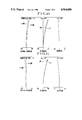
- FIG. 4 to FIG. 6 are aberration curves corresponding to the numerical examples 1-3, respectively, with an object distance of 3 m.
- FIG. 7 to FIG. 9 are lens block diagrams illustrating numerical examples 4-6 of the invention.
- FIG. 10 to FIG. 12 are aberration curves corresponding to the numerical examples 4-6, respectively, with an object distance of 3 m.
- FIG. 1 to FIG. 3 and FIG. 7 to FIG. 9 schematically show numerical examples 1 to 6 of embodiments of finder optical devices according to the invention, respectively.
- the finder optical device of the invention is arranged separately from the photographic lens (not shown).
- T is an objective lens unit comprising two positive lenses Ta and Tb arranged so that their lens surfaces of strong curvature face each other.
- the lens Tb plays chiefly the role of a field lens.
- a relay lens unit R comprises a negative lens Ra and a positive lens Rb.
- a field lens unit F is arranged in the neighborhood of a secondary image plane Q, and comprises a positive lens convex toward the front.
- An eyepiece lens unit E comprises two positive lenses Ea and Eb arranged so that their lens surfaces of strong curvature face each other.
- the objective lens unit T forms a first finder image on a primary image plane P
- the relay lens unit R and the field lens unit F then focus the light from the first finder image to form a non-reverse erecting second finder image on a secondary image plane Q.
- the non-reverse erecting second finder image formed on the secondary image plane Q is made to be observed by the eyepiece lens unit E.
- the finder optical device of the invention satisfies the following conditions:
- f T , f R , f F and f E are respectively the focal lengths of the objective lens unit T, the relay lens unit R, the field lens unit F and the eyepiece lens unit E.
- the inequalities of condition (1) concern with the refractive power arrangement of the relay lens unit R and the objective lens unit T, which is most important in the present embodiment.
- the focal lengths of the objective lens unit T and the relay lens unit R are made so determined that their ratio or f R /f T satisfies the condition (1).
- the inequalities of condition (2) have a main aim to minimize the diameter of the relay lens unit R.
- the focal lengths of the field lens unit F and the eyepiece lens unit E are made so determined that the principal ray of the off-axis pupil which is to pass through the center of the observation pupil passes through almost the center of the relay lens unit R. Therefore, despite the strengthening of the refractive power of the relay lens unit R, the light beam which would otherwise be refracted from the marginal zone of the lens can be avoided. Hence, the good quality can be secured over the entire area of the observation pupil.
- the relay lens unit R is constructed so as to satisfy the conditions (3) to (5), and the objective lens unit T and the eyepiece lens unit E each are constructed with the two lenses whose confronting surfaces are of strong curvature, so that the various aberrations are well canceled in each lens unit itself, thus achieving good balance of aberration correction.
- the inequalities of condition (3) concern with the radius of curvature of the cemented lens surface of the relay lens unit R.
- the curvature of field becomes difficult to correct.
- the lower limit is exceeded, the spherical aberration on the secondary image plane Q becomes over-corrected.
- condition (4) and (5) concern with the refractive indices and Abbe numbers of the materials of the negative lens Ra and the positive lens Rb constituting the relay lens unit R.
- condition (4) concerns with the refractive index difference for enabling the curvature of field to be corrected well
- condition (5) concerns with the Abbe number difference for enabling, among others, the longitudinal chromatic aberration to be corrected.
- the singlet lenses constituting the objective lens unit, the field lens unit and eyepiece lens unit arbitrary one or ones may otherwise be constructed in cemented form, comprising a positive lens and a negative lens cemented together. According to this, a finder optical device better corrected for chromatic aberrations and other aberration and having a higher grade of optical performance can be achieved.
- the objective lens unit T comprises two positive lenses Ta and Tb arranged so that their lens surfaces of strong curvature face each other.
- the lens Ta may be made up by a plurality of lenses for the purpose of improving aberration correction.
- the lens Tb plays the role of a field lens. Hence the primary image is formed in the neighborhood of the lens Tb.
- the relay lens unit R comprises a lens Ra of positive refractive power and a lens Rb of negative refractive power.
- An air lens is formed between the lenses Ra and Rb.
- the curvature of one of lens surfaces of the lens Ra of positive refractive power which faces the lens Rb of negative refractive power is stronger than that of the other surface.
- the field lens unit F comprises one positive lens turning its strong convexity to the object side.
- a secondary image is formed in the neighborhood of the field lens unit F.
- the eyepiece lens unit E comprises two positive lenses Ea and Eb, the surfaces of strong curvature of the lenses Ea and Eb facing each other.
- the refractive power arrangement of the relay lens unit R is the refractive power arrangement of the relay lens unit R.
- a longer composite focal length of the objective lens unit T enables the finder magnification to be greater, but causes the size at the primary image plane to get larger.
- the difficult point is in the aberration correction of the secondary image forming system.
- the secondary image forming system when the image magnification is unity, becomes shortest in the total length. The shorter the focal length of the relay lens unit R, the more advantageously the total length can be shortened, but the more difficult the aberrations become to correct.
- f P is the focal length of the lens Ra of positive refractive power of the relay lens unit R
- ⁇ P is the Abbe number of its material
- R P is the radius of curvature of its lens surface of strong curvature
- f N is the focal length of the lens Rb of negative refractive power of the relay lens unit R
- ⁇ N is the Abbe number of its material
- R N is the radius of curvature of its lens surface of strong curvature.
- the inequalities of condition (6) represent a preferable range on aberration correction for the focal lengths of the positive lens Ra and the negative lens Rb constituting the relay lens unit R when a shortening of the total length by strengthening the refractive power of the relay lens unit R is achieved.
- the composite focal length of the relay lens unit R has a positive refractive power
- the refractive power of the positive lens Ra becomes strong as exceeding the lower limit, although it is advantageous to shortening the total length, because the diverging action in the relay lens unit R weakens, under-corrected spherical aberration is produced.
- the refractive power of the negative lens Rb strengthens as exceeding the upper limit, it gets harder to achieve a shortening of the total length while well correcting the spherical aberration.
- condition (7) concerns with the difference between the Abbe numbers of the materials of the positive lens Ra and the negative lens Rb constituting the relay lens unit R.
- the difference between the Abbe numbers becomes smaller than the limit, correction of longitudinal chromatic aberration gets harder.
- the inequalities of condition (8) are to determine the shape of an air lens between the positive lens Ra and the negative lens Rb constituting the relay lens unit R.
- this air lens has a negative refractive power.
- the upper limit is exceeded, spherical aberration and curvature of field both get under-corrected. Conversely when the lower limit is exceeded, both of the spherical aberration and the curvature of field get over-corrected objectionably.
- the relay lens unit R of the secondary image forming system is divided into the positive lens Ra and the negative lens Rb, and their refractive powers are properly arranged, whereby an increase of the degree of freedom on aberration correction and a shortening of the optical total length can be achieved.
- Another advantage arising from the use of the divided form of the relay lens R into the positive lens Ra and the negative lens Rb is that it becomes even possible to choose synthetic resin or the like as the optical material.
- Ri is the radius of curvature of the i-th lens surface counting from front
- Di is the i-th lens thickness or air separation counting from front
- Ni and ⁇ i are respectively the refractive index and Abbe number of the glass of the i-th lens element counting from front.
Abstract
Description
1.0<f.sub.R /f.sub.T <1.8 . . . (1)
1.0<f.sub.F /f.sub.E <1.7 . . . (2)
______________________________________
Numerical Example 1 (FIGS. 1 and 4):
Exit Pupil Diameter φ3; Max. Emergence Angle tan Θ = 0.17
______________________________________
R1 =  33.14    D1 =    2.00 N1 = 1.49171
                                      ν1 = 57.4
R2 =  -9.63    D2 =    9.43
R3 =  7.79     D3 =    4.28 N2 = 1.49171
                                      ν2 = 57.4
R4 =  ∞  D4 =    31.40
R5 =  25.85    D5 =    0.72 N3 = 1.84666
                                      ν3 = 23.9
R6 =  7.24     D6 =    2.43 N4 = 1.77250
                                      ν4 = 49.6
R7 =  -22.44   D7 =    29.00
R8 =  10.62    D8 =    3.20 N5 = 1.49171
                                      ν5 = 57.4
R9 =  ∞  D9 =    24.86
R10 = ∞  D10 =   1.50 N6 = 1.49171
                                      ν6 = 57.4
R11 = -20.00   D11 =   0.15
R12 = 20.00    D12 =   1.50 N7 = 1.49171
                                      ν7 = 57.4
R13 = ∞
______________________________________
 Note:
 The eye point lies 16 mm behind the vertex of the lens surface R13.
 f.sub.T = 11.35, f.sub.R = 18.0, f.sub.F = 21.61, f.sub.E = 20.37
______________________________________
Numerical Example 2 (FIGS. 2 and 5):
Exit Pupil Diameter φ3; Max. Emergence Angle tan Θ = 0.17
______________________________________
R1 =  ∞   D1 =    1.80 N1 = 1.77250
                                      ν1 = 49.6
R2 =  -12.44    D2 =    9.60
R3 =  7.85      D3 =    2.80 N2 = 1.49171
                                      ν2 = 57.4
R4 =  -148.41   D4 =    28.89
R5 =  17.85     D5 =    0.80 N3 = 1.84666
                                      ν3 = 23.9
R6 =  7.27      D6 =    2.60 N4 = 1.71300
                                      ν4 = 53.8
R7 =  -18.74    D7 =    25.07
R8 =  11.09     D8 =    2.40 N5 = 1.49171
                                      ν5 = 57.4
R9 =  ∞   D9 =    22.01
R10 = 144.93    D10 =   1.80 N6 = 1.49171
                                      ν6 = 57.4
R11 = -20.70    D11 =   0.15
R12 = 20.70     D12 =   1.80 N7 = 1.49171
                                      ν7 = 57.4
R13 = - 144.93
______________________________________
 f.sub.T = 11.34, f.sub.R = 15.39, f.sub.F = 22.56, f.sub.E = 18.61
______________________________________
Numerical Example 3 (FIGS. 3 and 6):
Exit Pupil Diameter φ3; Max. Emergence Angle tan Θ = 0.17
______________________________________
R1 =  5458.52    D1 =    2.60 N1 = 1.49171
                                       ν1 = 57.4
R2 =  -8.01      D2 =    9.09
R3 =  8.01       D3 =    2.60 N2 = 1.49171
                                       ν2 = 57.4
R4 =  -5458.52   D4 =    32.92
R5 =  17.72      D5 =    0.80 N3 = 1.84666
                                       ν3 = 23.9
R6 =  7.24       D6 =    2.60 N4 = 1.69680
                                       ν4 = 55.5
R7 =  -20.84     D7 =    27.93
R8 =  12.13      D8 =    2.40 N5 = 1.49171
                                       ν5 = 57.4
R9 =  ∞    D9 =    22.07
R10 = 389.49     D10 =   1.80 N6 = 1.49171
                                       ν6 = 57.4
R11 = -19.15     D11 =   0.15
R12 = 19.15      D12 =   1.80 N7 = 1.49171
                                       ν7 = 57.4
R13 = -389.49
______________________________________
 f.sub.T = 11.30, f.sub.R = 17.0, f.sub.F = 24.68, f.sub.E = 18.66
              TABLE 1
______________________________________
          Numerical Example
Condition   1           2       3
______________________________________
(1) f.sub.R /f.sub.T
            1.59        1.36    1.50
(2) f.sub.F /f.sub.E
            1.06        1.21    1.32
(3) |RA|/f.sub.R
            0.40        0.47    0.43
(4) N.sub.N -N.sub.P
            0.074       0.134   0.150
(5) ν.sub.P -ν.sub.N
            25.7        29.9    31.6
______________________________________
______________________________________
Numerical Example 4 (FIGS. 7 and 10):
Exit Pupil Diameter φ3; Max. Emergence Angle tan Θ = 0.17
______________________________________
R1 =  33.142   D1 =    2.00 N1 = 1.49171
                                      ν1 = 57.4
R2 =  -9.632   D2 =    9.43
R3 =  7.799    D3 =    4.28 N2 = 1.49171
                                      ν2 = 57.4
R4 =  0.000    D4 =    30.49
R5 =  20.766   D5 =    2.43 N3 = 1.69680
                                      ν3 = 55.5
R6 =  -7.369   D6 =    0.15
R7 =  -6.828   D7 =    0.72 N4 = 1.58347
                                      ν4 = 30.2
R8 =  -45.349  D8 =    31.19
R9 =  10.627   D9 =    3.20 N5 = 1.49171
                                      ν5 = 57.4
R10 = 0.000    D10 =   24.86
R11 = 0.000    D11 =   1.50 N6 = 1.49171
                                      ν6 = 57.4
R12 = -20.000  D12 =   0.15
R13 = 20.000   D13 =   1.50 N7 = 1.49171
                                      ν7 = 57.4
R14 = 0.000
______________________________________
 Note:
 The eye point lies 16 mm behind the vertex of the lens surface R14.
 f.sub.p = 8.09 f.sub.N = -13.87
______________________________________
Numerical Example 5 (FIGS. 8 and 11):
Exit Pupil Diameter φ3; Max. Emergence Angle tan Θ = 0.17
______________________________________
R1 =  5032.000   D1 =    2.60 N1 = 1.49171
                                       ν1 = 57.4
R2 =  -8.086     D2 =    9.05
R3 =  8.086      D3 =    2.60 N2 = 1.49171
                                       ν2 = 57.4
R4 =  -5032.000  D4 =    29.78
R5 =  10.078     D5 =    0.80 N3 = 1.84666
                                       ν3 = 23.9
R6 =  6.343      D6 =    0.15
R7 =  6.986      D7 =    2.45 N4 = 1.49171
                                       ν4 = 57.4
R8 =  -11.800    D8 =    25.07
R9 =  11.091     D9 =    2.40 N5 = 1.49171
                                       ν5 = 57.4
R10 = -5032.000  D10 =   23.13
R11 = 144.930    D11 =   1.80 N6 = 1.49171
                                       ν6 = 57.4
R12 = -20.709    D12 =   0.15
R13 = 20.709     D13 =   1.80 N7 = 1.49171
                                       ν7 = 57.4
R14 = -144.930
______________________________________
 f.sub.P = 9.33 f.sub.N = -22.41
______________________________________
Numerical Example 6 (FIGS. 9 and 12):
Exit Pupil Diameter φ3; Max. Emergence Angle tan Θ = 0.17
______________________________________
R1 =  5458.520   D1 =    2.60 N1 = 1.49171
                                       ν1 = 57.4
R2 =  -8.017     D2 =    9.09
R3 =  8.017      D3 =    2.60 N2 = 1.49171
                                       ν2 = 57.4
R4 =  -5458.520  D4 =    32.72
R5 =  15.012     D5 =    0.72 N3 = 1.58347
                                       ν3 = 30.2
R6 =  4.807      D6 =    0.15
R7 =  4.936      D7 =    2.50 N4 = 1.49171
                                       ν4 = 57.4
R8 =  -11.802    D8 =    27.67
R9 =  12.135     D9 =    2.40 N5 = 1.49171
                                       ν5 = 57.4
R10 = 0.000      D10 =   22.07
R11 = 389.490    D11 =   1.80 N6 = 1.49171
                                       ν6 = 57.4
R12 = -19.154    D12 =   0.15
R13 = 19.154     D13 =   1.80 N7 = 1.49171
                                       ν7 =  57.4
R14 = -389.490
______________________________________
 f.sub.P = 7.44 f.sub.N = -12.44
Claims (10)
1.0<f.sub.R /f.sub.T <1.8
1.0<f.sub.F /f.sub.E <1.7
0.3<|f.sub.p /f.sub.N |<0.7
20<ν.sub.P -ν.sub.N
0≦(R.sub.P -R.sub.N)/(R.sub.P +R.sub.N)<0.1
1.0<f.sub.R /f.sub.T <1.8
1.0<f.sub.F /f.sub.E <1.7
Applications Claiming Priority (4)
| Application Number | Priority Date | Filing Date | Title |
|---|---|---|---|
| JP62-315549 | 1987-12-14 | ||
| JP62315549A JP2510138B2 (en) | 1987-12-14 | 1987-12-14 | Secondary imaging finder optical system |
| JP63-234159 | 1988-09-19 | ||
| JP63234159A JP2584844B2 (en) | 1988-09-19 | 1988-09-19 | Secondary imaging type viewfinder optical system |
Publications (1)
| Publication Number | Publication Date |
|---|---|
| US4964686A true US4964686A (en) | 1990-10-23 |
Family
ID=26531395
Family Applications (1)
| Application Number | Title | Priority Date | Filing Date |
|---|---|---|---|
| US07/280,584 Expired - Lifetime US4964686A (en) | 1987-12-14 | 1988-12-06 | Finder optical device |
Country Status (1)
| Country | Link |
|---|---|
| US (1) | US4964686A (en) |
Cited By (9)
| Publication number | Priority date | Publication date | Assignee | Title |
|---|---|---|---|---|
| US5124837A (en) * | 1989-12-20 | 1992-06-23 | Ricoh Company, Ltd. | Finder of real image type |
| US5194886A (en) * | 1990-04-03 | 1993-03-16 | Minolta Camera Kabushiki Kaisha | Finder optical system |
| US5257133A (en) * | 1991-09-11 | 1993-10-26 | Hughes Aircraft Company | Re-imaging optical system employing refractive and diffractive optical elements |
| US5632718A (en) * | 1994-03-11 | 1997-05-27 | Olympus Optical Co., Ltd. | Non-flexible endoscope with objective lens system and relay lens system |
| US5936775A (en) * | 1997-06-17 | 1999-08-10 | Asahi Kogaku Kogyo Kabushiki Kaisha | Real-image type optical finder |
| US6571059B1 (en) * | 1997-12-11 | 2003-05-27 | Olympus Optical Co., Ltd | Camera including a device for controlling the photographing optical systems to prevent obscuring of an image in the finder optical system |
| US20070014856A1 (en) * | 1996-12-25 | 2007-01-18 | Astellas Pharma Inc. | Rapidly disintegrable pharmaceutical composition |
| US20120281211A1 (en) * | 2010-11-05 | 2012-11-08 | University Of Ottawa | Miniaturized multimodal cars endoscope |
| US8867129B2 (en) * | 2010-01-19 | 2014-10-21 | Schmidt & Bender Gmbh Co. Kg | Sighting telescope |
Citations (6)
| Publication number | Priority date | Publication date | Assignee | Title |
|---|---|---|---|---|
| US2541014A (en) * | 1948-09-23 | 1951-02-13 | Eastman Kodak Co | Erector lens for low-power telescopes |
| US3045545A (en) * | 1960-11-10 | 1962-07-24 | Bausch & Lomb | Optical system for sighting instruments |
| US3127809A (en) * | 1960-02-27 | 1964-04-07 | Agfa Ag | Single lens reflex motion picture camera |
| US3989349A (en) * | 1973-02-06 | 1976-11-02 | Karl Vockenhuber | Reflex finder |
| US4270837A (en) * | 1979-04-02 | 1981-06-02 | Polaroid Corporation | Periscopic viewfinder system for use in photographic cameras |
| US4387967A (en) * | 1979-03-27 | 1983-06-14 | Minolta Camera Co., Ltd. | Optical system for use in single lens reflex cameras |
-
1988
- 1988-12-06 US US07/280,584 patent/US4964686A/en not_active Expired - Lifetime
Patent Citations (6)
| Publication number | Priority date | Publication date | Assignee | Title |
|---|---|---|---|---|
| US2541014A (en) * | 1948-09-23 | 1951-02-13 | Eastman Kodak Co | Erector lens for low-power telescopes |
| US3127809A (en) * | 1960-02-27 | 1964-04-07 | Agfa Ag | Single lens reflex motion picture camera |
| US3045545A (en) * | 1960-11-10 | 1962-07-24 | Bausch & Lomb | Optical system for sighting instruments |
| US3989349A (en) * | 1973-02-06 | 1976-11-02 | Karl Vockenhuber | Reflex finder |
| US4387967A (en) * | 1979-03-27 | 1983-06-14 | Minolta Camera Co., Ltd. | Optical system for use in single lens reflex cameras |
| US4270837A (en) * | 1979-04-02 | 1981-06-02 | Polaroid Corporation | Periscopic viewfinder system for use in photographic cameras |
Cited By (11)
| Publication number | Priority date | Publication date | Assignee | Title |
|---|---|---|---|---|
| US5124837A (en) * | 1989-12-20 | 1992-06-23 | Ricoh Company, Ltd. | Finder of real image type |
| US5194886A (en) * | 1990-04-03 | 1993-03-16 | Minolta Camera Kabushiki Kaisha | Finder optical system |
| US5257133A (en) * | 1991-09-11 | 1993-10-26 | Hughes Aircraft Company | Re-imaging optical system employing refractive and diffractive optical elements |
| US5632718A (en) * | 1994-03-11 | 1997-05-27 | Olympus Optical Co., Ltd. | Non-flexible endoscope with objective lens system and relay lens system |
| US5902232A (en) * | 1994-03-11 | 1999-05-11 | Olympus Optical Co., Ltd. | Non-flexible endoscope having a slender insert section |
| US20070014856A1 (en) * | 1996-12-25 | 2007-01-18 | Astellas Pharma Inc. | Rapidly disintegrable pharmaceutical composition |
| US5936775A (en) * | 1997-06-17 | 1999-08-10 | Asahi Kogaku Kogyo Kabushiki Kaisha | Real-image type optical finder |
| US6571059B1 (en) * | 1997-12-11 | 2003-05-27 | Olympus Optical Co., Ltd | Camera including a device for controlling the photographing optical systems to prevent obscuring of an image in the finder optical system |
| US8867129B2 (en) * | 2010-01-19 | 2014-10-21 | Schmidt & Bender Gmbh Co. Kg | Sighting telescope |
| US20120281211A1 (en) * | 2010-11-05 | 2012-11-08 | University Of Ottawa | Miniaturized multimodal cars endoscope |
| US8879058B2 (en) * | 2010-11-05 | 2014-11-04 | The University Of Ottawa | Miniaturized multimodal cars endoscope |
Similar Documents
| Publication | Publication Date | Title |
|---|---|---|
| US4830476A (en) | Compact zoom lens system | |
| US4260223A (en) | Lens system for photographing objects from infinity to a very short distance | |
| US5592334A (en) | Zoom lens system | |
| US4449791A (en) | Three-group zoom lens | |
| US5493446A (en) | Projection lens | |
| US5270863A (en) | Zoom lens system | |
| US4400064A (en) | Zoom lens | |
| US4542961A (en) | Triplet type objective | |
| JPS6048013B2 (en) | Finder optical system | |
| US4964686A (en) | Finder optical device | |
| JPH05297274A (en) | Kepler type zoom finder optical system | |
| US4770508A (en) | Conversion lens releasably attached behind master lens | |
| JP3650270B2 (en) | Real-image viewfinder | |
| US5541772A (en) | Camera zoom lens | |
| US4717245A (en) | High relative aperture Gauss type lens | |
| US5446590A (en) | High eye point type viewfinder optical system | |
| US4396255A (en) | Standard photographic lens system | |
| US5680249A (en) | Optical system for camera | |
| US4618234A (en) | Finder optical system for cameras | |
| US4708445A (en) | Large aperture ratio photographic lens system | |
| US4550987A (en) | Small size telephoto lens | |
| US4491394A (en) | Image-forming lens system | |
| JP2510138B2 (en) | Secondary imaging finder optical system | |
| JP3048248B2 (en) | Real image type variable magnification finder optical system | |
| US5689373A (en) | Eyepiece lens |
Legal Events
| Date | Code | Title | Description |
|---|---|---|---|
| AS | Assignment |
Owner name: CANON KABUSHIKI KAISHA, 3-30-2, SHIMOMARUKO, OHTA- Free format text: ASSIGNMENT OF ASSIGNORS INTEREST.;ASSIGNOR:KATO, MASATAKE;REEL/FRAME:004981/0628 Effective date: 19881129 Owner name: CANON KABUSHIKI KAISHA, A CORP. OF JAPAN, JAPAN Free format text: ASSIGNMENT OF ASSIGNORS INTEREST;ASSIGNOR:KATO, MASATAKE;REEL/FRAME:004981/0628 Effective date: 19881129 |
|
| STCF | Information on status: patent grant |
Free format text: PATENTED CASE |
|
| CC | Certificate of correction | ||
| CC | Certificate of correction | ||
| FEPP | Fee payment procedure |
Free format text: PAYOR NUMBER ASSIGNED (ORIGINAL EVENT CODE: ASPN); ENTITY STATUS OF PATENT OWNER: LARGE ENTITY |
|
| FPAY | Fee payment |
Year of fee payment: 4 |
|
| FPAY | Fee payment |
Year of fee payment: 8 |
|
| FEPP | Fee payment procedure |
Free format text: PAYOR NUMBER ASSIGNED (ORIGINAL EVENT CODE: ASPN); ENTITY STATUS OF PATENT OWNER: LARGE ENTITY Free format text: PAYER NUMBER DE-ASSIGNED (ORIGINAL EVENT CODE: RMPN); ENTITY STATUS OF PATENT OWNER: LARGE ENTITY |
|
| FPAY | Fee payment |
Year of fee payment: 12 |