US4963705A - Treadle assembly - Google Patents
Treadle assembly Download PDFInfo
- Publication number
- US4963705A US4963705A US07/336,365 US33636589A US4963705A US 4963705 A US4963705 A US 4963705A US 33636589 A US33636589 A US 33636589A US 4963705 A US4963705 A US 4963705A
- Authority
- US
- United States
- Prior art keywords
- treadle
- contact means
- flexible
- sheet
- fixed
- Prior art date
- Legal status (The legal status is an assumption and is not a legal conclusion. Google has not performed a legal analysis and makes no representation as to the accuracy of the status listed.)
- Expired - Fee Related
Links
Images

Classifications
-
- H—ELECTRICITY
- H01—ELECTRIC ELEMENTS
- H01H—ELECTRIC SWITCHES; RELAYS; SELECTORS; EMERGENCY PROTECTIVE DEVICES
- H01H3/00—Mechanisms for operating contacts
- H01H3/02—Operating parts, i.e. for operating driving mechanism by a mechanical force external to the switch
- H01H3/14—Operating parts, i.e. for operating driving mechanism by a mechanical force external to the switch adapted for operation by a part of the human body other than the hand, e.g. by foot
- H01H3/141—Cushion or mat switches
-
- G—PHYSICS
- G08—SIGNALLING
- G08G—TRAFFIC CONTROL SYSTEMS
- G08G1/00—Traffic control systems for road vehicles
- G08G1/01—Detecting movement of traffic to be counted or controlled
- G08G1/015—Detecting movement of traffic to be counted or controlled with provision for distinguishing between two or more types of vehicles, e.g. between motor-cars and cycles
-
- G—PHYSICS
- G08—SIGNALLING
- G08G—TRAFFIC CONTROL SYSTEMS
- G08G1/00—Traffic control systems for road vehicles
- G08G1/01—Detecting movement of traffic to be counted or controlled
- G08G1/02—Detecting movement of traffic to be counted or controlled using treadles built into the road
-
- H—ELECTRICITY
- H01—ELECTRIC ELEMENTS
- H01H—ELECTRIC SWITCHES; RELAYS; SELECTORS; EMERGENCY PROTECTIVE DEVICES
- H01H3/00—Mechanisms for operating contacts
- H01H3/02—Operating parts, i.e. for operating driving mechanism by a mechanical force external to the switch
- H01H3/14—Operating parts, i.e. for operating driving mechanism by a mechanical force external to the switch adapted for operation by a part of the human body other than the hand, e.g. by foot
- H01H3/141—Cushion or mat switches
- H01H2003/148—Cushion or mat switches the mat switch being composed by independently juxtaposed contact tiles, e.g. for obtaining a variable protected area
Definitions
- This invention relates generally to treadles which may be used in roadways to sense vehicular traffic flow.
- the invention is more particularly directed to a treadle assembly containing sealed therein a flexible circuit treadle apparatus designed to resist water and salts, to be longer lasting, easily replaceable, and difficult for vehicles to bypass.
- Conventional treadle assemblies generally comprise a rubber treadle envelope containing a pair of contact strips, which are generally heavy metal plates, arranged to actuate a counter, thereby providing a record of the passage of vehicles over a predetermined section of the roadway.
- Treadles have generally been utilized for counting of vehicular traffic and are conventionally disposed transversely on a roadway lane so that vehicles in that lane must pass over the treadle. Quite often treadles are placed at toll plazas which may be at a bridge, tunnel, expressway or the like.
- Treadles located at such installations are subjected to extreme wear and corrosion as a result of vehicles repeatedly rolling over the same portions of the treadle, and also as a result of frequent exposure to water, salt and other environmental factors. Consequently, the treadles must be frequently replaced.
- Conventional treadle assemblies also are stiff, and thus do not always make contact when depressed, and may be bypassed by vehicles as a result of wide spacing between the contact areas.
- the present invention provides a novel treadle assembly containing a lightweight flexible circuit which is pressure sensitive, easy to replace, and difficult to bypass.
- the circuit is completely sealed in the treadle and is thus more resistant to water, road salt and other environmental factors than conventional treadle assemblies.
- the present invention relates to a treadle assembly comprising a resilient envelope adapted to be disposed in a roadway and one or more flexible circuits disposed therein, said flexible circuits containing plurality of pairs of contacts to close under weight of a vehicle passing over the associated treadle contacts and to open when not subject to said weight.
- Each of said flexible circuits comprises superimposed top and bottom sheets of a resilient flexible material, joined at their edges to form a substantially flat envelope; one or more movable electrically conductive contact means adjacent the top sheet; one or more fixed electrically conductive contact means adjacent the bottom sheet; and a flexible spacer disposed between said fixed and said movable contact means, said flexible spacer material having open areas therein such that when pressure is applied to the treadle assembly at each open area said movable contact means will deflect to engage said fixed contact means at that area.
- It is an object of the invention to provide a treadle assembly comprising a resilient envelope adapted to be disposed in a roadway and one or more flexible circuits disposed therein, said flexible circuits containing a plurality of pairs of contacts to close under weight of a vehicle passing over the treadle and to open when not subject to said weight.
- It is a further object of the present invention to provide a flexible circuit comprising superimposed top and bottom sheets of a resilient flexible material, joined at their edges to form a substantially flat envelope; a plurality of movable contact means adjacent the top sheet; a fixed contact means adjacent the bottom sheet; a flexible spacer disposed between said fixed and said movable contact mean and having defined open areas therein; and a conductive elastomeric sheet disposed between said spacer and said fixed contacts. Said elastomeric sheet deflects upward when pressure is applied to the treadle surface which provides better contact through the open areas in the spacer material.
- a further object of the invention is to provide a lightweight treadle apparatus which can be longer lasting and easily replaced.
- Another object of the invention is to provide a treadle apparatus having a plurality of contact areas, spaced apart in a configuration which is difficult to bypass.
- An object of the invention is to provide a flexible circuit for a treadle apparatus wherein the open areas of the spacer are arranged in rows across the width of the treadle, and said rows form an angle of 0-55 degrees with the length of the treadle.
- Another object of the invention is to provide a treadle apparatus which is resistant to corrosion by water and road salt.
- Yet another object of the invention is to provide a treadle switch assembly which is more sensitive to pressure than prior art assemblies thereby providing a more accurate count of vehicular traffic flow.
- this invention provides a treadle assembly comprising a laminated or extruded envelope of resilient elastomeric material adapted to be disposed in a roadway, and having disposed therein one or more flexible circuits.
- Each of said flexible circuits comprises one or more movable contacts and one or more fixed contacts contained therein.
- the movable contacts are separated from the fixed contacts by a spacer sheet which contains open areas whereby the passage of a wheel over the treadle causes the upper movable contacts to engage the lower contacts.
- Said engagement activates a counting means connected to the treadle apparatus by electrical leads attached to the contacts at one or both ends of the length of the treadle.
- Said fixed and movable contacts are sealed within a substantially flat envelope of flexible, resilient material to prevent attack by water, sand and road salts and additionally to provide a supporting carrier for the thin, flexible contacts.
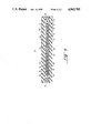
- FIG. 1 is a top planar view of the flexible circuit according to one embodiment of this invention.
- FIG. 2 is a top view of the top and bottom sheets of the flexible circuit with the movable contacts disposed adjacent the top sheet and the fixed contact disposed adjacent the bottom sheet.
- FIG. 3 shows the spacer means according to one embodiment of this invention.
- FIG. 4 shows the spacer means according to an alternate embodiment of the invention.
- FIG. 5 is a cross-sectional view of a treadle switch assembly according to one embodiment of the invention, having two flexible circuits disposed therein.
- FIG. 1 there is shown a flexible circuit 10 according to one preferred embodiment, and embodying the principles of this invention.
- the circuit preferably has a length sufficient to extend substantially across an entire lane of roadway when sealed in the treadle assembly. Generally, this length is at least from about eight feet to about twelve feet.
- Said circuit apparatus is sealed at its horizontal edges 11.
- leads 23 Prior to sealing, leads 23 are attached, preferably by soldering, to the contacts.
- the leads may be encapsulated at the point of attachment with an appropriate sealant, to further protect the leads from corrosion and contamination by road salt, etc.
- Said leads generally run into a cable such as flat cable 22.
- FIG. 1 will be explained in conjunction with FIG. 2 and FIG. 3, which show the separate layers of the circuit prior to assembly.
- FIG. 1 will be explained in conjunction with FIG. 2 and FIG. 3, which show the separate layers of the circuit prior to assembly.
- FIG. 1 will be explained in conjunction with FIG. 2 and FIG. 3, which show the separate layers of the circuit prior to assembly.
- FIG. 2 shows the top and bottom sheets of flexible material, 11A and 11B, which will be sealed together at the horizontal edges 11, as shown in FIG. 1. Also shown in FIG. 2 are the movable contacts 12 and the fixed contact 13 which are adjacent top sheet 11A and bottom sheet 11B respectively.
- FIG. 2 shows one embodiment of the invention, in which there are six movable contacts 12 and a single fixed contact 13. However, neither the number of movable contacts nor the number of fixed contacts is critical to the apparatus and thus may be one or more, provided the movable contacts are capable of engaging the fixed contacts.
- FIG. 3 shows the spacer 14 which separates the movable contacts from the fixed contacts.
- the spacer 14 contains open areas 15, which in this embodiment of the invention are arranged in a diagonal row which forms an angle of approximately 45 degrees with the length of the spacer 14.
- Said open areas may be rectangular, as shown in FIG. 3, square, oval or of any other useful shape.
- these diagonal rows form an angle of from about 0 to about 55 degrees with the length of the spacer and said rows are spaced from about two to about five inches apart.
- This arrangement of open areas provides contact areas over a large area of the treadle apparatus, thereby making the treadle difficult for vehicles to bypass.
- the open areas are arranged as shown in FIG. 4.
- FIG. 5 a cross-sectional view is shown of the assembled treadle apparatus 17 having two flexible circuits 10 disposed therein. Like parts are numbered corresponding to FIGS. 1-3.
- an additional, optional layer 16 of the flexible circuits 10 is shown.
- Layer 16 comprises a sheet of conductive elastomeric material which enhances the contact area when the movable and fixed contacts are engaged. It should be noted that the layers are superimposed such that the movable contact strips 12 are aligned with the open areas 15 of the spacer. In an embodiment having multiple fixed contact strips instead of the continuous fixed contact 13, said fixed contacts would also be aligned with movable contacts 12 and open areas 15.
- top and bottom sheets 11A and 11B are of approximately equal thickness, from about 0.002 inches to about 0.030 inches and Preferably about 0.005 inches;
- movable contacts 12 and fixed contact 13 are of approximately equal thickness, from about 0.002 inches to about 0.020 inches and preferably about 0.002 inches;
- spacer sheet 14 is of a thickness of from about 0.004 inches to about 0.030 inches and preferably about 0.010 inches, and the conductive elastomeric sheet 16 is from about 0.010 inches to about 0.050 inches and preferably about 0.018 inches.
- the top and bottom sheets 11A and B and spacer sheet 14 are of a flexible resilient material, for example a flexible polyester sheet known as Mylar®.
- the fixed and movable contacts may be formed of any electrically conductive material, but are preferably of a metal sheet or foil, e.g. tin plated copper, copper, stainless steel, silver plated copper, nickel, and other conductive metal foils.
- the contacts are permanently laminated to their respective top or bottom sheet. More preferably, the contacts are formed by laminating a solid metal foil to a top or bottom sheet and then the foil is cut by a rotary cutter to create the multiple contact strips.
- the conductive elastomeric sheet may be any type of electrically conductive elastomeric material, e.g.
- a silicone elastomer filled with a conductive filler such as silver, silver plated fillers, copper, nickel, carbon black, etc.
- conductive sheets are well known and commercially available, such as CHO-SEAL®, CHO-SIL®or CHO-FOAM® conductive sheet stock, available from Chomerics, Inc.
- the layers of the circuit should be sealed at edges 11 in order to prevent the intrusion of water and other contaminants. This could be accomplished using various joining methods well known to those skilled in the art; a preferred method is by application of a pressure sensitive adhesive. Pressure sensitive adhesive may also be used to bond the fixed and movable contacts to the bottom and top sheets respectively, and to bond the spacer sheet to its adjacent layers.
- the treadle assembly comprises two flexible circuit treadle circuits 10 disposed within a treadle envelope of resilient elastomeric material.
- the resilient treadle envelope can be formed of various elastomeric materials such as natural or synthetic rubbers or synthetic elastomers using conventional methods.
- the envelope is formed of neoprene rubber which is laminated using a neoprene cement.
- Top and bottom pieces 18 are laminated at their edges to end pieces 19 and at their centers to spacer 21, leaving two openings 20 into which the treadle switches 10 are placed.
- the length of the outer resilient envelope formed by 18, 19 and 21 is approximately equal to that of the treadle circuits 10.
- the width of the outer envelope will be determined by the number of treadle circuits 10 to be used, which may be one or more as well as the width required or desired by the user. Other dimensions are not critical and may be varied to adapt the treadle switch assembly 17 to be disposed in a given roadway surface.
- the elements of the treadle apparatus 17 have the following dimensions: top and bottom pieces 18 are 10.5 inches wide by 100 inches long by 0.50 inches thick; end pieces 19, disposed between top and bottom pieces 18, are 2.0 inches wide by 100 inches long by 0.050 inches thick; spacer 21 is 0.50 inches wide by 100 inches long by 0.050 inches thick.
- two openings 20 are provided having dimensions three inches wide by 100 inches long by 0.050 inches deep into which two treadle circuits 10 are placed.
- the treadle envelope may be an integrally extruded elastomer, an elastomer extruded or molded directly onto a metal plate, or other types of resiliant envelopes.
- the flexible circuits are completely sealed, they may be used, without an outer envelope, as the treadle assembly itself. However, it is preferred to include the outer envelope in order to further render the treadle resistant to wear, water, road salt and other environmental factors.
Landscapes
- Physics & Mathematics (AREA)
- General Physics & Mathematics (AREA)
- Push-Button Switches (AREA)
- Traffic Control Systems (AREA)
- Road Paving Structures (AREA)
Abstract
Description
Claims (23)
Priority Applications (4)
| Application Number | Priority Date | Filing Date | Title |
|---|---|---|---|
| US07/336,365 US4963705A (en) | 1989-04-11 | 1989-04-11 | Treadle assembly |
| CA002011733A CA2011733A1 (en) | 1989-04-11 | 1990-03-08 | Treadle assembly |
| EP19900303617 EP0392736A3 (en) | 1989-04-11 | 1990-04-04 | Treadle assembly |
| JP2089306A JPH02287899A (en) | 1989-04-11 | 1990-04-05 | Stepboard assembly |
Applications Claiming Priority (1)
| Application Number | Priority Date | Filing Date | Title |
|---|---|---|---|
| US07/336,365 US4963705A (en) | 1989-04-11 | 1989-04-11 | Treadle assembly |
Publications (1)
| Publication Number | Publication Date |
|---|---|
| US4963705A true US4963705A (en) | 1990-10-16 |
Family
ID=23315756
Family Applications (1)
| Application Number | Title | Priority Date | Filing Date |
|---|---|---|---|
| US07/336,365 Expired - Fee Related US4963705A (en) | 1989-04-11 | 1989-04-11 | Treadle assembly |
Country Status (4)
| Country | Link |
|---|---|
| US (1) | US4963705A (en) |
| EP (1) | EP0392736A3 (en) |
| JP (1) | JPH02287899A (en) |
| CA (1) | CA2011733A1 (en) |
Cited By (15)
| Publication number | Priority date | Publication date | Assignee | Title |
|---|---|---|---|---|
| US5083110A (en) * | 1991-02-04 | 1992-01-21 | Richard Ahrens | Window alarm system |
| US5115109A (en) * | 1988-08-17 | 1992-05-19 | Fisher James R | Speed detector for traffic control |
| US5373128A (en) * | 1993-07-29 | 1994-12-13 | The Revenue Markets, Inc. | Wheel sensing treadle matrix switch assembly for roadways |
| US5448028A (en) * | 1993-12-10 | 1995-09-05 | Davidson Textron, Inc. | Armrest electrical switch arrangement with soft interior trim panel |
| US5465998A (en) * | 1995-03-17 | 1995-11-14 | Larry J. Winget | Air bag cover having a tear seam membrane switch |
| US5510586A (en) * | 1995-01-11 | 1996-04-23 | Tapeswitch Corporation Of America | Switch joint for electrical switching mats |
| US5646615A (en) * | 1994-10-26 | 1997-07-08 | Moore; Curtis W. | Treadle and roadway treadle assembly |
| US6297743B1 (en) * | 1997-11-22 | 2001-10-02 | Gencorp Property Inc. | Force-responsive detectors and systems |
| US6469266B2 (en) * | 2000-05-30 | 2002-10-22 | International Road Dynamics Inc. | Road vehicle axle sensor |
| US20100096247A1 (en) * | 2006-12-21 | 2010-04-22 | Dav | Electric control module, particularly for motor vehicles |
| ITVE20120006A1 (en) * | 2012-02-10 | 2013-08-11 | G M Electronics S R L | DEVICE FOR DETECTING PASSAGE OF PERSONS AND / OR OBJECTS THROUGH A VARCO. |
| US20160153828A1 (en) * | 2014-12-01 | 2016-06-02 | Haenni Instruments Ag | Force sensor device for detecting the weight of a vehicle |
| US9612148B2 (en) | 2014-02-20 | 2017-04-04 | Xerox Corporation | Sensor detecting multiple weights of multiple items |
| US20170138804A1 (en) * | 2014-03-31 | 2017-05-18 | Institut Francais Des Sciences Et Technologies Des Transports, De L'aménagement Et Des Réseaux | An acquisition device, a method of fabricating it, and a method of measuring force |
| US20170178839A1 (en) * | 2015-12-17 | 2017-06-22 | Foster Electric Co., Ltd. | Switch-containing cable |
Families Citing this family (5)
| Publication number | Priority date | Publication date | Assignee | Title |
|---|---|---|---|---|
| US5260520A (en) * | 1992-04-02 | 1993-11-09 | Martin Marietta Energy Systems, Inc. | Apparatus for weighing and identifying characteristics of a moving vehicle |
| FR2726928A1 (en) * | 1994-11-15 | 1996-05-15 | Grenobloise Electronique Autom | Selective detection system of vehicles wheels on roadway |
| IL152105A0 (en) | 2000-04-03 | 2003-07-31 | Univ Brunel | Conductive pressure sensitive textile |
| GB0404419D0 (en) | 2004-02-27 | 2004-03-31 | Intelligent Textiles Ltd | Electrical components and circuits constructed as textiles |
| BR112018010317A2 (en) | 2015-12-18 | 2018-12-04 | Intelligent Textiles Ltd | conductive fabric, method of manufacturing a conductive fabric, same system and article of clothing |
Citations (22)
| Publication number | Priority date | Publication date | Assignee | Title |
|---|---|---|---|---|
| US2251351A (en) * | 1940-12-03 | 1941-08-05 | Cooper Benjamin | Treadle process |
| US2736630A (en) * | 1952-10-29 | 1956-02-28 | Res Electronics & Devices Co I | Toll checking system |
| US2858394A (en) * | 1957-06-11 | 1958-10-28 | Hopkins Russell | Pressure mat |
| US2885508A (en) * | 1956-03-05 | 1959-05-05 | Eastern Ind Inc | Vehicle detector |
| US3056005A (en) * | 1960-08-04 | 1962-09-25 | Harry J Larson | Mat switch and method of making the same |
| US3090941A (en) * | 1963-05-21 | Toll collecting device | ||
| US3136833A (en) * | 1957-11-26 | 1964-06-09 | Republic Industries | Method of making mat type floor switches |
| US3748443A (en) * | 1971-07-01 | 1973-07-24 | S Kroll | Wheel sensing apparatus |
| US3835449A (en) * | 1972-05-24 | 1974-09-10 | J Viracola | Method and apparatus for classifying the tire width of moving vehicles |
| US4178948A (en) * | 1978-09-06 | 1979-12-18 | Swinehart Lonn L | Apparatus for use in cleaning vehicle tires |
| US4192394A (en) * | 1978-06-26 | 1980-03-11 | Simpson Cullie M | Alarm system for platform scale |
| US4455465A (en) * | 1983-01-10 | 1984-06-19 | Automatic Toll Systems, Inc. | Treadle assembly with plural replaceable treadle switches |
| US4471177A (en) * | 1982-08-13 | 1984-09-11 | Press On, Inc. | Enlarged switch area membrane switch and method |
| US4483076A (en) * | 1982-11-30 | 1984-11-20 | The United States Of America As Represented By The Secretary Of The Army | Ground contact area measurement device |
| US4551595A (en) * | 1984-07-16 | 1985-11-05 | Tapeswitch Corporation Of America | Tape switch with corrugated wavy conductor |
| US4587385A (en) * | 1977-02-28 | 1986-05-06 | Augusto Capecchi | Touch pad indicating arrival during swimming contest |
| US4602135A (en) * | 1985-05-30 | 1986-07-22 | Phalen Robert F | Membrane switch |
| US4661664A (en) * | 1985-12-23 | 1987-04-28 | Miller Norman K | High sensitivity mat switch |
| US4707570A (en) * | 1985-02-12 | 1987-11-17 | Ricoh Company, Ltd. | Manual information input device |
| US4716413A (en) * | 1986-02-05 | 1987-12-29 | Ernest Haile | Drunk driver detection system |
| US4787243A (en) * | 1987-01-13 | 1988-11-29 | Electronique Serge Dassault | Device for detecting a dimension, in particular a tread width on a path |
| US4799381A (en) * | 1988-02-21 | 1989-01-24 | Cmi International, Inc. | Vehicle road sensor |
Family Cites Families (2)
| Publication number | Priority date | Publication date | Assignee | Title |
|---|---|---|---|---|
| US4401896A (en) * | 1981-05-26 | 1983-08-30 | Fowler Eugene W | Weight or ambient pressure-responsive mechanical pressure switch |
| US4839480A (en) * | 1986-11-05 | 1989-06-13 | The Gates Rubber Company | Vehicle sensing device |
-
1989
- 1989-04-11 US US07/336,365 patent/US4963705A/en not_active Expired - Fee Related
-
1990
- 1990-03-08 CA CA002011733A patent/CA2011733A1/en not_active Abandoned
- 1990-04-04 EP EP19900303617 patent/EP0392736A3/en not_active Withdrawn
- 1990-04-05 JP JP2089306A patent/JPH02287899A/en active Pending
Patent Citations (22)
| Publication number | Priority date | Publication date | Assignee | Title |
|---|---|---|---|---|
| US3090941A (en) * | 1963-05-21 | Toll collecting device | ||
| US2251351A (en) * | 1940-12-03 | 1941-08-05 | Cooper Benjamin | Treadle process |
| US2736630A (en) * | 1952-10-29 | 1956-02-28 | Res Electronics & Devices Co I | Toll checking system |
| US2885508A (en) * | 1956-03-05 | 1959-05-05 | Eastern Ind Inc | Vehicle detector |
| US2858394A (en) * | 1957-06-11 | 1958-10-28 | Hopkins Russell | Pressure mat |
| US3136833A (en) * | 1957-11-26 | 1964-06-09 | Republic Industries | Method of making mat type floor switches |
| US3056005A (en) * | 1960-08-04 | 1962-09-25 | Harry J Larson | Mat switch and method of making the same |
| US3748443A (en) * | 1971-07-01 | 1973-07-24 | S Kroll | Wheel sensing apparatus |
| US3835449A (en) * | 1972-05-24 | 1974-09-10 | J Viracola | Method and apparatus for classifying the tire width of moving vehicles |
| US4587385A (en) * | 1977-02-28 | 1986-05-06 | Augusto Capecchi | Touch pad indicating arrival during swimming contest |
| US4192394A (en) * | 1978-06-26 | 1980-03-11 | Simpson Cullie M | Alarm system for platform scale |
| US4178948A (en) * | 1978-09-06 | 1979-12-18 | Swinehart Lonn L | Apparatus for use in cleaning vehicle tires |
| US4471177A (en) * | 1982-08-13 | 1984-09-11 | Press On, Inc. | Enlarged switch area membrane switch and method |
| US4483076A (en) * | 1982-11-30 | 1984-11-20 | The United States Of America As Represented By The Secretary Of The Army | Ground contact area measurement device |
| US4455465A (en) * | 1983-01-10 | 1984-06-19 | Automatic Toll Systems, Inc. | Treadle assembly with plural replaceable treadle switches |
| US4551595A (en) * | 1984-07-16 | 1985-11-05 | Tapeswitch Corporation Of America | Tape switch with corrugated wavy conductor |
| US4707570A (en) * | 1985-02-12 | 1987-11-17 | Ricoh Company, Ltd. | Manual information input device |
| US4602135A (en) * | 1985-05-30 | 1986-07-22 | Phalen Robert F | Membrane switch |
| US4661664A (en) * | 1985-12-23 | 1987-04-28 | Miller Norman K | High sensitivity mat switch |
| US4716413A (en) * | 1986-02-05 | 1987-12-29 | Ernest Haile | Drunk driver detection system |
| US4787243A (en) * | 1987-01-13 | 1988-11-29 | Electronique Serge Dassault | Device for detecting a dimension, in particular a tread width on a path |
| US4799381A (en) * | 1988-02-21 | 1989-01-24 | Cmi International, Inc. | Vehicle road sensor |
Cited By (20)
| Publication number | Priority date | Publication date | Assignee | Title |
|---|---|---|---|---|
| US5115109A (en) * | 1988-08-17 | 1992-05-19 | Fisher James R | Speed detector for traffic control |
| US5083110A (en) * | 1991-02-04 | 1992-01-21 | Richard Ahrens | Window alarm system |
| US5373128A (en) * | 1993-07-29 | 1994-12-13 | The Revenue Markets, Inc. | Wheel sensing treadle matrix switch assembly for roadways |
| US5448028A (en) * | 1993-12-10 | 1995-09-05 | Davidson Textron, Inc. | Armrest electrical switch arrangement with soft interior trim panel |
| US5646615A (en) * | 1994-10-26 | 1997-07-08 | Moore; Curtis W. | Treadle and roadway treadle assembly |
| US5510586A (en) * | 1995-01-11 | 1996-04-23 | Tapeswitch Corporation Of America | Switch joint for electrical switching mats |
| US5465998A (en) * | 1995-03-17 | 1995-11-14 | Larry J. Winget | Air bag cover having a tear seam membrane switch |
| US6297743B1 (en) * | 1997-11-22 | 2001-10-02 | Gencorp Property Inc. | Force-responsive detectors and systems |
| US6469266B2 (en) * | 2000-05-30 | 2002-10-22 | International Road Dynamics Inc. | Road vehicle axle sensor |
| US20100096247A1 (en) * | 2006-12-21 | 2010-04-22 | Dav | Electric control module, particularly for motor vehicles |
| ITVE20120006A1 (en) * | 2012-02-10 | 2013-08-11 | G M Electronics S R L | DEVICE FOR DETECTING PASSAGE OF PERSONS AND / OR OBJECTS THROUGH A VARCO. |
| US9612148B2 (en) | 2014-02-20 | 2017-04-04 | Xerox Corporation | Sensor detecting multiple weights of multiple items |
| US20170138804A1 (en) * | 2014-03-31 | 2017-05-18 | Institut Francais Des Sciences Et Technologies Des Transports, De L'aménagement Et Des Réseaux | An acquisition device, a method of fabricating it, and a method of measuring force |
| US10989612B2 (en) * | 2014-03-31 | 2021-04-27 | Institut Francais Des Sciences Et Technologies Des Transport, De L'amenagement Et Des Reseaux | Sensor with a plurality of acquisition devices that measure force using impedance |
| US20160153828A1 (en) * | 2014-12-01 | 2016-06-02 | Haenni Instruments Ag | Force sensor device for detecting the weight of a vehicle |
| US10041826B2 (en) * | 2014-12-01 | 2018-08-07 | Haenni Instruments Ag | Force sensor device for detecting the weight of a vehicle |
| US20170178839A1 (en) * | 2015-12-17 | 2017-06-22 | Foster Electric Co., Ltd. | Switch-containing cable |
| CN106898508A (en) * | 2015-12-17 | 2017-06-27 | 丰达电机株式会社 | switch built-in cable |
| CN106898508B (en) * | 2015-12-17 | 2018-10-30 | 丰达电机株式会社 | The built-in cable of switch |
| US10211009B2 (en) * | 2015-12-17 | 2019-02-19 | Foster Electric Company Limited | Switch-containing cable |
Also Published As
| Publication number | Publication date |
|---|---|
| EP0392736A2 (en) | 1990-10-17 |
| EP0392736A3 (en) | 1991-03-20 |
| JPH02287899A (en) | 1990-11-27 |
| CA2011733A1 (en) | 1990-10-11 |
Similar Documents
| Publication | Publication Date | Title |
|---|---|---|
| US4963705A (en) | Treadle assembly | |
| US4366463A (en) | Keyboard | |
| CN1113369C (en) | Electrical devices | |
| EP0800721B1 (en) | Keyboard | |
| US5674018A (en) | Weatherproof electronic keypad with replaceable graphics overlay | |
| US4013851A (en) | Vehicle detection apparatus | |
| CA2023631C (en) | Electrical double-layer capacitor | |
| US5218177A (en) | Screened pattern causing gaps around keyboard membrane spacer hole to increase venting and reduced bounce | |
| CA1106428A (en) | Control panel overlay | |
| CA2792005A1 (en) | Rail joint bars and rail joint assemblies | |
| US5115109A (en) | Speed detector for traffic control | |
| CA2310149C (en) | In road vehicle axle sensor | |
| JPH0997536A (en) | Sheet-form switch | |
| US4217473A (en) | Connecting flexible switch | |
| US7358456B1 (en) | Swimming pool touchpad | |
| EP0289197A2 (en) | Electro-optical device | |
| KR960019828A (en) | Cell consisting of two parallel plate plastic support plates with electrodes and separated from each other | |
| AU7925198A (en) | Spark-resistant structure, in particular for aircraft | |
| CA2077870A1 (en) | Click-action membrane switch unit | |
| EP0168227B1 (en) | Anisotropic electric conductive rubber connector | |
| US5373128A (en) | Wheel sensing treadle matrix switch assembly for roadways | |
| EP0077887A2 (en) | Membrane switch | |
| US4403122A (en) | Membrane switch assembly with modular switch and spacer portions | |
| US5656988A (en) | Force sensors with segmental electrodes | |
| DE3585761D1 (en) | ELECTRICAL CONTACT BETWEEN ELEMENTS WITH DIFFERENT SPECIFIC RESISTANCE. |
Legal Events
| Date | Code | Title | Description |
|---|---|---|---|
| AS | Assignment |
Owner name: CHOMERICS, INC., 77 DRAGON COURT, WOBURN, MASSACHU Free format text: ASSIGNMENT OF ASSIGNORS INTEREST.;ASSIGNORS:BRODERICK, JOHN;JONES, PETER;SQUITIERI, VINCENT;REEL/FRAME:005091/0901;SIGNING DATES FROM |
|
| AS | Assignment |
Owner name: CHOMERICS, INC., MASSACHUSETTS Free format text: ASSIGNMENT OF ASSIGNORS INTEREST.;ASSIGNORS:BRODERICK, JOHN;JONES, PETER;SQUITIERI, VINCENT;REEL/FRAME:005252/0952;SIGNING DATES FROM 19900220 TO 19900306 |
|
| FPAY | Fee payment |
Year of fee payment: 4 |
|
| AS | Assignment |
Owner name: PARKER-HANNIFIN CORPORATION, OHIO Free format text: MERGER;ASSIGNOR:CHOMERICS, INC.;REEL/FRAME:007715/0433 Effective date: 19950623 |
|
| AS | Assignment |
Owner name: PARKER INTANGIBLES INC., DELAWARE Free format text: ASSIGNMENT OF ASSIGNORS INTEREST;ASSIGNOR:PARKER-HANNIFIN CORPORATION;REEL/FRAME:008000/0503 Effective date: 19960607 |
|
| REMI | Maintenance fee reminder mailed | ||
| LAPS | Lapse for failure to pay maintenance fees | ||
| FP | Lapsed due to failure to pay maintenance fee |
Effective date: 19981016 |
|
| STCH | Information on status: patent discontinuation |
Free format text: PATENT EXPIRED DUE TO NONPAYMENT OF MAINTENANCE FEES UNDER 37 CFR 1.362 |