US495391A - Bicycle saddle - Google Patents
Bicycle saddle Download PDFInfo
- Publication number
- US495391A US495391A US495391DA US495391A US 495391 A US495391 A US 495391A US 495391D A US495391D A US 495391DA US 495391 A US495391 A US 495391A
- Authority
- US
- United States
- Prior art keywords
- saddle
- plate
- spring
- secured
- bolt
- Prior art date
- Legal status (The legal status is an assumption and is not a legal conclusion. Google has not performed a legal analysis and makes no representation as to the accuracy of the status listed.)
- Expired - Lifetime
Links
- 238000010276 construction Methods 0.000 description 3
- 230000004048 modification Effects 0.000 description 3
- 238000012986 modification Methods 0.000 description 3
- 101100113998 Mus musculus Cnbd2 gene Proteins 0.000 description 1
- 230000003247 decreasing effect Effects 0.000 description 1
- 235000015250 liver sausages Nutrition 0.000 description 1
- 238000004519 manufacturing process Methods 0.000 description 1
- 239000002184 metal Substances 0.000 description 1
Images


Classifications
-
- B—PERFORMING OPERATIONS; TRANSPORTING
- B62—LAND VEHICLES FOR TRAVELLING OTHERWISE THAN ON RAILS
- B62J—CYCLE SADDLES OR SEATS; AUXILIARY DEVICES OR ACCESSORIES SPECIALLY ADAPTED TO CYCLES AND NOT OTHERWISE PROVIDED FOR, e.g. ARTICLE CARRIERS OR CYCLE PROTECTORS
- B62J1/00—Saddles or other seats for cycles; Arrangement thereof; Component parts
- B62J1/10—Internal adjustment of saddles
Definitions
- FRANK D CABLE, OF TOLEDO, OHIO, ASSIGN OR, BY DIRECT AND MESNE ASSIGNMENTS, TO THE YOST MANUFACTURING COMPANY, OF SAME PLACE.
- This invention relates to certain new and useful improvements in saddles for bicycles.
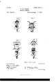
- Figure 1 is a side elevation of a saddle and its connecting devices constructed in accordance with my invention.
- Fig. 2 is a central longitudinal section of the same.
- Fig. 3 is a perspective view of the securing plate connected on the under side of the cantle of the saddle.
- Fig. 4 is a similar view of the securing plate connected to the under side of the pommel of the saddle.
- Fig. 5 is a vertical section taken at the line 0:, 0c, of Fig. 2.
- Fig. 6 is a section taken at line y, y, of Fig. 2.
- Fig. 7 is a rear view 'of saddle and rear end of spring with the saddle partly broken away to show connections.
- Fig. 8 is a front view of spring and saddle.
- Fig. 9 is a side elevation of a saddle showing a modification of the means employed for adjusting the saddle.
- A represents a cylindrical slide adapted to move upon the arm of the saddle post of a bicycle and to be secured in any desired position by a clamping screw bolt B.
- the slide A is formed with an upwardly projecting flat plate C pivoted at D to a plate E formed with a head F adapted to bear against the under side of the saddle spring G, and formed with an arc-shaped slot H, through which is passed a bolt I, through the medium of which and a nut K, the extension C and plate'E are adj ustably secured together in an obvious manner.
- L is a clamping plate adapted to lie upon the upper surface of the saddle spring, and which is formed with vertical sides inwardly flanged to grasp the under side of the head F of the plate E as clearly shown at Fig. 5.
- the saddle spring may be clamped atadj ustable distances from either end, and that it may be inclined in either direction longitudinally by reason of the pivotal and adjustable connection between the extension C and plate F.
- the spring G is a flat spring, straight fora suitable distance to permit of the necessary limit of adjustment forward and backward, and having its rearend bent or coiled as seen at O, to a C-shape, the extreme end formed into a square socket as shown at P, Figs. 2 and 6, to receive a square bolt Q, each end of which is turned cylindrical and provided with a screw thread to receive securing nuts R.
- the radial arms S are two radial arms fitting over the square portion of the bolt Q, extending each side of the spring G, and secured in place by the nuts R above referred to.
- the radial arms S have their upper free ends turned outwardly and about horizontal and enter the pockets 0., a, in the cantle plate T fully illustrated at Fig. 3, which plate T is secured to the saddle by rivets in the well known manner.
- the forward end of the spring Cris also bent or curved and the extreme end fashioned into a cylinder to receive a round bolt U, provided with a suitable head and nut, by means of which it is secured in place.
- the end of the front portion of the spring is bifurcated or formed with a longitudinal slot 6, to receive a vibratory lever arm V, which is secured pivotally to the spring by the bolt U passing through a hole in said lever arm.
- the upper end of the lever arm V is extended laterally on each side forming a trunnion 0 adapted to enter and interlock with the front curved .end of a pommel plate W (see Fig. l), secured to the under side of the saddle proper by suitable rivets.
- the rod Y passes through a post Z secured by nut or in any other manner to the plate E, and is held in any given position therein by a binding screw (1, or any other suitable clamping device.
- the saddle proper may be removed speedily from a bicycle by simply releasing the binding screw d within the post Z on the plate E, and vibrating the lever arm V sufficiently to disengage its-upper trunnioned end from the hook end of the pommel plate.
- the plate adapted to receive the post Z either side of the center, so that it may be secured in place either end forward.
- the plate E provided with arc-shaped slot in the bottom end,and pivoted to the extension O; the clamping plate L and clamping bolt M, whereby the saddle may be adjusted longitudinally-and vertically substantially as and for the purpose set forth.
Landscapes
- Engineering & Computer Science (AREA)
- Mechanical Engineering (AREA)
- Steering Devices For Bicycles And Motorcycles (AREA)
Description
(No Model.) 3 Sheets-Sheet 1.
P. D. CABLE. BIGYGLBSADDILB.
No. 495,391. Pate nted Apr. 11, 1893.
THE Nonms PETERS co, PuoTuLm-xou WASHINGTON, D, c
3 Sheets -Sheet 2.
(No Model F. D. CABLE.
BICYCLE SADDLE.
Patented Apr. 11, 1893.
ms. noims PETERS co. rum-mums wAsumsmNfD. c.
(No Model.) 3Sheets-Sheet 3. F. D. CABLE.
' BICYCLE SADDLE. No. 495,391; PatentedApr. 1.1, 1893, l
ZU/fnesses v I Ffankflfl (Z6556, //7ven/Z0r M 37 I i v I UNITED STATES.
PATENT OFFICE.
FRANK D. CABLE, OF TOLEDO, OHIO, ASSIGN OR, BY DIRECT AND MESNE ASSIGNMENTS, TO THE YOST MANUFACTURING COMPANY, OF SAME PLACE.
BICYCLE-SADDLE.
SPECIFICATION forming part of Letters Patent No. 495,391, dated April 11, 1893. Application filed August 9,1892. Serial No. 442.567. (No model.)
To all whom it mag concern.
Be it known that I, FRANK D. CABLE, a citizen of the United States, residing at Toledo,
in the county of Lucas and State of Ohio, have invented certain new and useful Improvements in Bicycle-Saddles; and I do hereby declare the following to be a full, clear, and exact description of the invention, such as will enable others skilled in the art to which it appertains to make and use the same.
This invention relates to certain new and useful improvements in saddles for bicycles.
It has for its objects to provide means by which the saddle proper can be readily secured in place or removed, and also by which the spring tension and position of the saddle can be expeditiously adjusted.
With these ends in view my invention consists in the details of construction hereinafter described and claimed and fully shown in the accompanying drawings forming part of this specification.
In the accompanying drawings, Figure 1 is a side elevation of a saddle and its connecting devices constructed in accordance with my invention. Fig. 2 is a central longitudinal section of the same. Fig. 3 is a perspective view of the securing plate connected on the under side of the cantle of the saddle. Fig. 4 isa similar view of the securing plate connected to the under side of the pommel of the saddle. Fig. 5 is a vertical section taken at the line 0:, 0c, of Fig. 2. Fig. 6 is a section taken at line y, y, of Fig. 2. Fig. 7 is a rear view 'of saddle and rear end of spring with the saddle partly broken away to show connections. Fig. 8 is a front view of spring and saddle. Fig. 9 is a side elevation of a saddle showing a modification of the means employed for adjusting the saddle.
Similar letters denote like parts in the several figures of the drawings.
A represents a cylindrical slide adapted to move upon the arm of the saddle post of a bicycle and to be secured in any desired position by a clamping screw bolt B. The slide A is formed with an upwardly projecting flat plate C pivoted at D to a plate E formed with a head F adapted to bear against the under side of the saddle spring G, and formed with an arc-shaped slot H, through which is passed a bolt I, through the medium of which and a nut K, the extension C and plate'E are adj ustably secured together in an obvious manner.
L is a clamping plate adapted to lie upon the upper surface of the saddle spring, and which is formed with vertical sides inwardly flanged to grasp the under side of the head F of the plate E as clearly shown at Fig. 5.
Andwhen in proper relation with said head F a tight connection is made with the spring G, by means of aclamping bolt M which bears against the upper surface of the spring directly, or upon a thin interposed metal plate N, seen at Fig. 5.
From the construction and arrangement of parts thus far described, it will be seen that the saddle spring may be clamped atadj ustable distances from either end, and that it may be inclined in either direction longitudinally by reason of the pivotal and adjustable connection between the extension C and plate F. v
The spring G is a flat spring, straight fora suitable distance to permit of the necessary limit of adjustment forward and backward, and having its rearend bent or coiled as seen at O, to a C-shape, the extreme end formed into a square socket as shown at P, Figs. 2 and 6, to receive a square bolt Q, each end of which is turned cylindrical and provided with a screw thread to receive securing nuts R.
S, S, are two radial arms fitting over the square portion of the bolt Q, extending each side of the spring G, and secured in place by the nuts R above referred to. The radial arms S have their upper free ends turned outwardly and about horizontal and enter the pockets 0., a, in the cantle plate T fully illustrated at Fig. 3, which plate T is secured to the saddle by rivets in the well known manner. The forward end of the spring Cris also bent or curved and the extreme end fashioned into a cylinder to receive a round bolt U, provided with a suitable head and nut, by means of which it is secured in place. The end of the front portion of the spring is bifurcated or formed with a longitudinal slot 6, to receive a vibratory lever arm V, which is secured pivotally to the spring by the bolt U passing through a hole in said lever arm.
The upper end of the lever arm V is extended laterally on each side forming a trunnion 0 adapted to enter and interlock with the front curved .end of a pommel plate W (see Fig. l), secured to the under side of the saddle proper by suitable rivets. This lever arm Vis bifurcated at its lower end as clearly shown at Fig. 8, to straddle and move freely over the spring G and the lower ends are connected by a bolt and nut X, which also passes through the hollow sleeve end of a rod Y, by means of which the bifurcated and pivoted lever arm V. is vibrated. The rod Y passes through a post Z secured by nut or in any other manner to the plate E, and is held in any given position therein by a binding screw (1, or any other suitable clamping device.
When the ends of the arms S, S, have been placed within the pockets at, in the cantle plate T, and the upper trunnion end a of the lever arm V has been located within the hooked or curved end of the pommel plate W, the rod Y is passed through the post Z, and the lever-arm V vibrated toward the front of the saddle until a secure interlock is established between the pommel plate and the trunnion end of lever arm, and the parts are then secured in position by turning down the binding screw 01 in the post Z, and it will be seen that the tension of the spring G may be increased by the rearward movement of the lower bifurcated end of the lever arm V or decreased by a reverse movement.
With the construction illustrated and described it will be seen that the saddle proper may be removed speedily from a bicycle by simply releasing the binding screw d within the post Z on the plate E, and vibrating the lever arm V sufficiently to disengage its-upper trunnioned end from the hook end of the pommel plate. I have shown the plate adapted to receive the post Z either side of the center, so that it may be secured in place either end forward.
In lieu of the adjusting device shown in Fig. l I may employ the modification of the same shown in Fig. 9. This modification consists in providing the bar or rod Y with a series of notches or recesses which adapt it to interlock with a pin Z on the plate E. The
general contour or design of the said plate may be varied at will as such design or contour forms no part of my invention, so long as provision is made for sustaining in position the post Z. Variations may also be made in many other details without departing from the spirit of my invention.
What I claim as new, and desire to secure by Letters Patent, is-
1. In a saddle for bicycles, the combination with cantle plate T provided with pockets at, a, and the pommel plate W constructed as described, the spring G, radial arms S, S, secured fixedly to the rear end of the spring, lever arm V pivotally connected to the forward portion of the spring and securing rod Y, adapted to be secured adjustably to the plate E, substantially as and for the purpose set forth.
2. In a saddle for bicycles the combination with the spring G, and lever arm V,pivotally connected therewith, of the tension adjusting rod Y, plate E, post Z, and clamping screw d, substantially as and for the purpose set forth.
3. In combination with the sliding sleeve A, provided with clamping bolt B and extension 0, the plate E provided with arc-shaped slot in the bottom end,and pivoted to the extension O; the clamping plate L and clamping bolt M, whereby the saddle may be adjusted longitudinally-and vertically substantially as and for the purpose set forth.
4. The plate E interposed between the saddle post and the saddle spring, and formed with a head F to bear against the under side of the spring G, in combination with the clamping plate L, constructed as described, and the clamping screw M, whereby the parts may be readily separable for adjustment or removal as hereinbefore set forth.
5. In a bicycle saddle the radial arms S, S, secured over the squared projections of the bolt Q and locked in position by the nuts R, and having their free ends seated within the pockets 0., a, of the cantle plate T, in combination with the saddle and the saddle spring G, substantially as and for the purposes set forth.
In testimony whereof I affix my signaturein presence of two witnesses.
FRANK D. CABLE.
Witnesses:
JOHNSON THURSTON, W. H. Rooms.
Publications (1)
| Publication Number | Publication Date |
|---|---|
| US495391A true US495391A (en) | 1893-04-11 |
Family
ID=2564230
Family Applications (1)
| Application Number | Title | Priority Date | Filing Date |
|---|---|---|---|
| US495391D Expired - Lifetime US495391A (en) | Bicycle saddle |
Country Status (1)
| Country | Link |
|---|---|
| US (1) | US495391A (en) |
Cited By (1)
| Publication number | Priority date | Publication date | Assignee | Title |
|---|---|---|---|---|
| US20100244508A1 (en) * | 2007-04-04 | 2010-09-30 | Stefano Segato | Bicycle saddle structure and method of assembly thereof |
-
0
- US US495391D patent/US495391A/en not_active Expired - Lifetime
Cited By (2)
| Publication number | Priority date | Publication date | Assignee | Title |
|---|---|---|---|---|
| US20100244508A1 (en) * | 2007-04-04 | 2010-09-30 | Stefano Segato | Bicycle saddle structure and method of assembly thereof |
| US8371649B2 (en) * | 2007-04-04 | 2013-02-12 | Selle Royal S.P.A. | Bicycle saddle structure and method of assembly thereof |
Similar Documents
| Publication | Publication Date | Title |
|---|---|---|
| US510993A (en) | Mechanism for automatically operating the adjustable saddles of bicycles | |
| US492740A (en) | Gun-clip for bicycles | |
| US495391A (en) | Bicycle saddle | |
| US551016A (en) | Saddle-clip for bicycles | |
| US1033156A (en) | Combined back-rest, luggage-carrier, and handle-bar. | |
| US537376A (en) | Bicycle-saddle | |
| US565425A (en) | donlevy | |
| US597055A (en) | Bicycle-saddle | |
| US458609A (en) | Ernest james willis | |
| US523115A (en) | Bicycle-saddle | |
| US605689A (en) | Bicycle-saddle | |
| US468998A (en) | mcglinchey | |
| US566352A (en) | Max strohbach | |
| US1070319A (en) | Extension-frame for bicycles. | |
| US707262A (en) | Cushion-frame for bicycles or like vehicles. | |
| US596699A (en) | Bicycle saddle-post | |
| US405780A (en) | Device | |
| US494408A (en) | Frank d | |
| US473388A (en) | Velocipede-saddle | |
| US469628A (en) | Saddle for bicycles | |
| US473609A (en) | Walter brampton | |
| US525190A (en) | levi m | |
| US499379A (en) | Bicycle or velocipede saddle | |
| US664638A (en) | Spring-seat attachment. | |
| US1154308A (en) | Twin-saddle attachment for motor-cycles. |